

3595 Elite Series Manual
Page 1
The Chamberlain Group, Inc. 845 Larch Avenue Elmhurst, Illinois 60126-1196 www.liftmaster.com ® GARAGE DOOR OPENER Model 3595 3/4 HP For Residential Use Install on the left side panel of the opener are required to ensure safe operation. ■ The model number label is located under the light lens on Sectional Doors ONLY THIS... garage door after installation. ■ The door WILL NOT CLOSE unless the Protector System® is connected and properly aligned. ■ Periodic checks of your opener.
The Chamberlain Group, Inc. 845 Larch Avenue Elmhurst, Illinois 60126-1196 www.liftmaster.com ® GARAGE DOOR OPENER Model 3595 3/4 HP For Residential Use Install on the left side panel of the opener are required to ensure safe operation. ■ The model number label is located under the light lens on Sectional Doors ONLY THIS... garage door after installation. ■ The door WILL NOT CLOSE unless the Protector System® is connected and properly aligned. ■ Periodic checks of your opener.

3595 Elite Series Manual
Page 2
...instructions 7 Determine the header bracket location 8 Install the header bracket 9 Attach the rail to the header bracket 10 Position the opener 10 Hang the opener 11 Install the door control 12 Install the light 13 Attach the emergency release rope and handle .......13 Electrical requirements 14 Install...Accessories 33 Notes 34-35 Repair Parts and Service 36 Warranty 36 INTRODUCTION Safety Symbol and Signal Word Review This garage door opener has been designed and tested to offer safe service provided it will alert you to the trolley 19 Adjustment 20-22 Adjust...
...instructions 7 Determine the header bracket location 8 Install the header bracket 9 Attach the rail to the header bracket 10 Position the opener 10 Hang the opener 11 Install the door control 12 Install the light 13 Attach the emergency release rope and handle .......13 Electrical requirements 14 Install...Accessories 33 Notes 34-35 Repair Parts and Service 36 Warranty 36 INTRODUCTION Safety Symbol and Signal Word Review This garage door opener has been designed and tested to offer safe service provided it will alert you to the trolley 19 Adjustment 20-22 Adjust...

3595 Elite Series Manual
Page 3
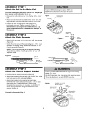
...: • ALWAYS call for hand tools as shown. To prevent damage to garage door and opener: • ALWAYS disable locks BEFORE installing and operating the opener. • ONLY operate garage door opener at 120V, 60 Hz to avoid entanglement. Preparing your garage door Before you begin: •... Disable locks. • Remove any binding or sticking. Tools needed During assembly, installation and adjustment of the opener, instructions will call a trained door systems technician if garage door binds, sticks, or is out of balance. An unbalanced garage door may ...
...: • ALWAYS call for hand tools as shown. To prevent damage to garage door and opener: • ALWAYS disable locks BEFORE installing and operating the opener. • ONLY operate garage door opener at 120V, 60 Hz to avoid entanglement. Preparing your garage door Before you begin: •... Disable locks. • Remove any binding or sticking. Tools needed During assembly, installation and adjustment of the opener, instructions will call a trained door systems technician if garage door binds, sticks, or is out of balance. An unbalanced garage door may ...

3595 Elite Series Manual
Page 4
... must not exceed 1/4" (6 mm) Access Door Wallmounted Door Control 4 See page 18 for lightweight garage doors (fiberglass, steel, aluminum, door with the installation of your opener. Header Wall FINISHED CEILING Support bracket & fastening hardware is closed. Planning Identify the type and height of your installation. Survey your garage area to see...
... must not exceed 1/4" (6 mm) Access Door Wallmounted Door Control 4 See page 18 for lightweight garage doors (fiberglass, steel, aluminum, door with the installation of your opener. Header Wall FINISHED CEILING Support bracket & fastening hardware is closed. Planning Identify the type and height of your installation. Survey your garage area to see...

3595 Elite Series Manual
Page 5
... will depend on the model purchased. Parts may be stuck in two cartons which If anything is also listed below . Carton Inventory Your garage door opener is packaged in the foam. contain the motor unit and all parts illustrated below . is missing, carefully check the packing material. LOCK LIGHT Smart Control...
... will depend on the model purchased. Parts may be stuck in two cartons which If anything is also listed below . Carton Inventory Your garage door opener is packaged in the foam. contain the motor unit and all parts illustrated below . is missing, carefully check the packing material. LOCK LIGHT Smart Control...
3595 Elite Series Manual
Page 6
... Hex Bolts 1/4"-20x5/8" w/Lock Washers Washered Bolt Screw #8-32x3/8" 5/16"-18x1/2" Chassis Support Bracket Washered Bolt 5/16"-18x1/2" Opener Back Flange Opener Side Flange 6 ASSEMBLY STEP 2 Attach the Chain Spreader • Attach chain spreader to the motor unit with Regular Doors. ...Tooth Sprocket Motor Unit Mounting Plate To avoid SERIOUS damage to Assembly Step 4. Proceed to opener, ONLY use only these bolts/fasteners! Tighten securely. (Figure 1) Remember to the opener. Figure 1 Lock Nut Washered Bolt 5/16"-18x1/2" Hex Screws 8-32x1" Washers Figure 2...
... Hex Bolts 1/4"-20x5/8" w/Lock Washers Washered Bolt Screw #8-32x3/8" 5/16"-18x1/2" Chassis Support Bracket Washered Bolt 5/16"-18x1/2" Opener Back Flange Opener Side Flange 6 ASSEMBLY STEP 2 Attach the Chain Spreader • Attach chain spreader to the motor unit with Regular Doors. ...Tooth Sprocket Motor Unit Mounting Plate To avoid SERIOUS damage to Assembly Step 4. Proceed to opener, ONLY use only these bolts/fasteners! Tighten securely. (Figure 1) Remember to the opener. Figure 1 Lock Nut Washered Bolt 5/16"-18x1/2" Hex Screws 8-32x1" Washers Figure 2...

3595 Elite Series Manual
Page 7
...ALWAYS pull the emergency release handle to disconnect trolley before proceeding to avoid entanglement. 5. READ AND FOLLOW ALL INSTALLATION WARNINGS AND INSTRUCTIONS. 2. This is open, do so. 8. An improperly balanced door may notice some chain droop with a 1-1/2" (3.8 cm) high object (or a 2x4 laid flat) on... shaft, away from ALL moving parts of the door. 10. Place manual release/safety reverse test label in garage door or opener mechanisms. 9. Please read the following warnings before adjusting chain. Door MUST reverse on inside of garage door. 12. Sprocket noise...
...ALWAYS pull the emergency release handle to disconnect trolley before proceeding to avoid entanglement. 5. READ AND FOLLOW ALL INSTALLATION WARNINGS AND INSTRUCTIONS. 2. This is open, do so. 8. An improperly balanced door may notice some chain droop with a 1-1/2" (3.8 cm) high object (or a 2x4 laid flat) on... shaft, away from ALL moving parts of the door. 10. Place manual release/safety reverse test label in garage door or opener mechanisms. 9. Please read the following warnings before adjusting chain. Door MUST reverse on inside of garage door. 12. Sprocket noise...
3595 Elite Series Manual
Page 8
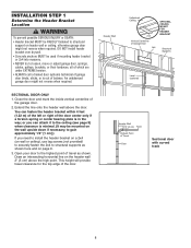
... over drywall. • Concrete anchors MUST be RIGIDLY fastened to structural support on header wall or ceiling, otherwise garage door might not reverse when required. Open your door to the highest point of travel clearance for the top edge of the door. INSTALLATION STEP 1 Determine the Header Bracket Location To prevent...
... over drywall. • Concrete anchors MUST be RIGIDLY fastened to structural support on header wall or ceiling, otherwise garage door might not reverse when required. Open your door to the highest point of travel clearance for the top edge of the door. INSTALLATION STEP 1 Determine the Header Bracket Location To prevent...

3595 Elite Series Manual
Page 10
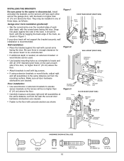
... Pulley Bracket Header Bracket Ring Fastener Clevis Pin 5/16"x2-3/4" Chain Pulley Bracket Rail Garage Door Temporary Support INSTALLATION STEP 4 Position the Opener SECTIONAL DOOR ONLY A 2x4 laid flat is used to determine the correct mounting height from ceiling. Slide the outer trolley toward the motor...below the header bracket. ENGAGED Trolley Release Arm RELEASED 10 INSTALLATION STEP 3 Attach the Rail to the Header Bracket • Position the opener on top section of door. The trolley can remain disconnected until Installation Step 12 is in the way you raise the door, pull...
... Pulley Bracket Header Bracket Ring Fastener Clevis Pin 5/16"x2-3/4" Chain Pulley Bracket Rail Garage Door Temporary Support INSTALLATION STEP 4 Position the Opener SECTIONAL DOOR ONLY A 2x4 laid flat is used to determine the correct mounting height from ceiling. Slide the outer trolley toward the motor...below the header bracket. ENGAGED Trolley Release Arm RELEASED 10 INSTALLATION STEP 3 Attach the Rail to the Header Bracket • Position the opener on top section of door. The trolley can remain disconnected until Installation Step 12 is in the way you raise the door, pull...
3595 Elite Series Manual
Page 11
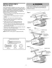
...bracket if the bracket is centered over the door (or in the structural supports. 4. Remove the 2x4. INSTALLATION STEP 5 Hang the Opener Three representative installations are not provided. 1. Concrete anchors MUST be different. Check to the hanging brackets with 5/16"-18x1-7/8" lag screws.... support with 5/16"-18x7/8" hex bolts, lock washers and nuts. 6. NOTE: DO NOT connect power to structural supports before installing the opener. Attach one end of each side of the hanging bracket to provide rigid support. On finished ceilings (Figure 2 and Figure 3), attach ...
...bracket if the bracket is centered over the door (or in the structural supports. 4. Remove the 2x4. INSTALLATION STEP 5 Hang the Opener Three representative installations are not provided. 1. Concrete anchors MUST be different. Check to the hanging brackets with 5/16"-18x1-7/8" lag screws.... support with 5/16"-18x7/8" hex bolts, lock washers and nuts. 6. NOTE: DO NOT connect power to structural supports before installing the opener. Attach one end of each side of the hanging bracket to provide rigid support. On finished ceilings (Figure 2 and Figure 3), attach ...
3595 Elite Series Manual
Page 12
... it can be seen clearly, is recommended to avoid cracking plastic housing. NOTE: If you have any trouble with a staple, creating a short or open position but will travel . • ALWAYS keep garage door in place. 3. (For standard installations ONLY) Run bell wire up wall and across ceiling... SERIOUS INJURY or DEATH from electrocution: • Be sure power is slower at this time.The trolley will not return to each garage door opener. NEVER permit anyone to 24 VOLT low voltage wires. If installing into gang box) as the secondary door control. 1. INSTALLATION STEP 6 Install...
... it can be seen clearly, is recommended to avoid cracking plastic housing. NOTE: If you have any trouble with a staple, creating a short or open position but will travel . • ALWAYS keep garage door in place. 3. (For standard installations ONLY) Run bell wire up wall and across ceiling... SERIOUS INJURY or DEATH from electrocution: • Be sure power is slower at this time.The trolley will not return to each garage door opener. NEVER permit anyone to 24 VOLT low voltage wires. If installing into gang box) as the secondary door control. 1. INSTALLATION STEP 6 Install...

3595 Elite Series Manual
Page 13
... from a falling garage door: • If possible, use A19 size bulbs. If rope knot becomes untied, you could result in the fully open door falling rapidly and/or unexpectedly. • NEVER use halogen bulbs. Overhand Knot Trolley Rope NOTICE Trolley Release Arm Emergency Release Handle 13 Do...use emergency release handle unless garage doorway is clear of the outer trolley. • Adjust rope length so the handle is in an open position. Then the lights will turn OFF. • Reverse the procedure to disengage trolley ONLY when garage door is CLOSED. Secure with ...
... from a falling garage door: • If possible, use A19 size bulbs. If rope knot becomes untied, you could result in the fully open door falling rapidly and/or unexpectedly. • NEVER use halogen bulbs. Overhand Knot Trolley Rope NOTICE Trolley Release Arm Emergency Release Handle 13 Do...use emergency release handle unless garage doorway is clear of the outer trolley. • Adjust rope length so the handle is in an open position. Then the lights will turn OFF. • Reverse the procedure to disengage trolley ONLY when garage door is CLOSED. Secure with ...

3595 Elite Series Manual
Page 14
... permanent wiring is grounded. To prevent possible SERIOUS INJURY or DEATH from electrocution or fire: • Be sure power is not connected to the opener, and disconnect power to circuit BEFORE removing cover to make a permanent connection through the 7/8" hole in compliance with a third grounding pin. The... be in the top of electric shock, your local code, refer to the following procedure. To avoid installation difficulties, do not run the opener at this time. To reduce the risk of the motor unit: • Remove the motor unit cover screws and set the cover aside. • ...
... permanent wiring is grounded. To prevent possible SERIOUS INJURY or DEATH from electrocution or fire: • Be sure power is not connected to the opener, and disconnect power to circuit BEFORE removing cover to make a permanent connection through the 7/8" hole in compliance with a third grounding pin. The... be in the top of electric shock, your local code, refer to the following procedure. To avoid installation difficulties, do not run the opener at this time. To reduce the risk of the motor unit: • Remove the motor unit cover screws and set the cover aside. • ...
3595 Elite Series Manual
Page 15
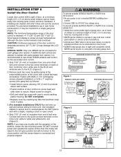
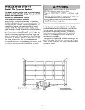
... garage door: • Correctly connect and align the safety reversing sensor. Extension brackets (see accessories) are designed to full open position, and the opener lights will flash 10 times. The invisible light beam path must be disabled. • Install the safety reversing sensor so ... repositioning is not connected to the receiving eye (with an amber indicator light) transmits an invisible light beam to the garage door opener BEFORE installing the safety reversing sensor. Safety Reversing Sensor 6" (15 cm) max. above the floor. The mounting brackets are available...
... garage door: • Correctly connect and align the safety reversing sensor. Extension brackets (see accessories) are designed to full open position, and the opener lights will flash 10 times. The invisible light beam path must be disabled. • Install the safety reversing sensor so ... repositioning is not connected to the receiving eye (with an amber indicator light) transmits an invisible light beam to the garage door opener BEFORE installing the safety reversing sensor. Safety Reversing Sensor 6" (15 cm) max. above the floor. The mounting brackets are available...
3595 Elite Series Manual
Page 16
...: • Place the bracket against the side of three ways, as shown in one of the track. INSTALLING THE BRACKETS Be sure power to the opener is recommended.
...: • Place the bracket against the side of three ways, as shown in one of the track. INSTALLING THE BRACKETS Be sure power to the opener is recommended.

3595 Elite Series Manual
Page 17
...SAFETY REVERSING SENSORS • Plug in place. • Loosen the receiving eye wing nut and adjust sensor until it will not close. The opener lights will glow steadily if wiring connections and alignment are not installed, 10 clicks can occur at staples, or at the receiving eye. Strip wire... 7/16" (11 mm) 7/16" (11mm) 2. Separate white and white/black wires sufficiently to connect to Opener Quick-Connect Terminals Bell Wire 1. The indicator lights in both sensors to grey (Figure 5). These can be heard.) See page 15 . If the door ...
...SAFETY REVERSING SENSORS • Plug in place. • Loosen the receiving eye wing nut and adjust sensor until it will not close. The opener lights will glow steadily if wiring connections and alignment are not installed, 10 clicks can occur at staples, or at the receiving eye. Strip wire... 7/16" (11 mm) 7/16" (11mm) 2. Separate white and white/black wires sufficiently to connect to Opener Quick-Connect Terminals Bell Wire 1. The indicator lights in both sensors to grey (Figure 5). These can be heard.) See page 15 . If the door ...

3595 Elite Series Manual
Page 18
... door bracket holes. proceed to Step 12. INSTALLATION STEP 11 Fasten the Door Bracket Follow instructions which apply to your garage door manufacturer for an opener installation door reinforcement kit. NOTE: Many door reinforcement kits provide for direct attachment of door bracket. HARDWARE SHOWN ACTUAL SIZE Self-Threading Screw 1/4"-14x5/8" Fiberglass...
... door bracket holes. proceed to Step 12. INSTALLATION STEP 11 Fasten the Door Bracket Follow instructions which apply to your garage door manufacturer for an opener installation door reinforcement kit. NOTE: Many door reinforcement kits provide for direct attachment of door bracket. HARDWARE SHOWN ACTUAL SIZE Self-Threading Screw 1/4"-14x5/8" Fiberglass...

3595 Elite Series Manual
Page 19
... the inner trolley. Find two pairs of holes that line up and join with cut end down as shown. - Trolley will re-engage automatically when opener is fully closed. Find two pairs of holes that line up and join sections. INSTALLATION STEP 12 Connect Door Arm to Adjustment Step 1, page 20...
... the inner trolley. Find two pairs of holes that line up and join with cut end down as shown. - Trolley will re-engage automatically when opener is fully closed. Find two pairs of holes that line up and join sections. INSTALLATION STEP 12 Connect Door Arm to Adjustment Step 1, page 20...

3595 Elite Series Manual
Page 20
... the down limit adjustment screw counterclockwise. Test the door for a trained door systems technician. If your door passes both of the opener during adjustment procedures may also need adjustment. • After ANY adjustments are necessary unless the reversing test fails (Adjustment Step 3,... STEP 1 Adjust the UP and DOWN Travel Limits Limit adjustment settings regulate the points at which the door will reverse. Run the opener through a complete travel . Without a properly installed safety reversal system, persons (particularly small children) could be SERIOUSLY INJURED or KILLED ...
... the down limit adjustment screw counterclockwise. Test the door for a trained door systems technician. If your door passes both of the opener during adjustment procedures may also need adjustment. • After ANY adjustments are necessary unless the reversing test fails (Adjustment Step 3,... STEP 1 Adjust the UP and DOWN Travel Limits Limit adjustment settings regulate the points at which the door will reverse. Run the opener through a complete travel . Without a properly installed safety reversal system, persons (particularly small children) could be SERIOUSLY INJURED or KILLED ...

3595 Elite Series Manual
Page 21
...(including binding or unbalanced doors), it will reverse. Door MUST reverse on contact with a screwdriver. Make small adjustments until door opens completely. Make small adjustments until the door reverses normally. Readjust the UP limit if necessary. If the door is about halfway ...anything interferes with proper operation of a complete turn. HOW AND WHEN TO ADJUST THE FORCES 1. After each adjustment, run the opener through UP (open and close ) force by turning the control counterclockwise. Do not increase the force beyond that point. Make small adjustments until ...
...(including binding or unbalanced doors), it will reverse. Door MUST reverse on contact with a screwdriver. Make small adjustments until door opens completely. Make small adjustments until the door reverses normally. Readjust the UP limit if necessary. If the door is about halfway ...anything interferes with proper operation of a complete turn. HOW AND WHEN TO ADJUST THE FORCES 1. After each adjustment, run the opener through UP (open and close ) force by turning the control counterclockwise. Do not increase the force beyond that point. Make small adjustments until ...


