3585 Elite Series Manual
Page 1
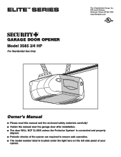
® GARAGE DOOR OPENER Model 3585 3/4 HP For Residential Use Only The Chamberlain Group, Inc. 845 Larch Avenue Elmhurst, Illinois 60126-1196 www.liftmaster.com Owner's Manual ■ Please read this manual and the enclosed safety materials carefully! ■ Fasten the manual near the garage door after installation. ■ The door WILL NOT CLOSE unless the...
® GARAGE DOOR OPENER Model 3585 3/4 HP For Residential Use Only The Chamberlain Group, Inc. 845 Larch Avenue Elmhurst, Illinois 60126-1196 www.liftmaster.com Owner's Manual ■ Please read this manual and the enclosed safety materials carefully! ■ Fasten the manual near the garage door after installation. ■ The door WILL NOT CLOSE unless the...
3585 Elite Series Manual
Page 2
Mechanical Electrical When you see this manual. The hazard may come from something mechanical or from motor unit memory 33 3-Button remotes 33 To add, reprogram or change a Keyless Entry PIN . . . .34 ... safety instructions 26 Using your garage door opener 26 Using the wall-mounted door control 27 Using the remote control 28 To open the door manually 29 Care of your garage door and/or the garage door opener if you do not comply with the instructions and warnings contained in this...
Mechanical Electrical When you see this manual. The hazard may come from something mechanical or from motor unit memory 33 3-Button remotes 33 To add, reprogram or change a Keyless Entry PIN . . . .34 ... safety instructions 26 Using your garage door opener 26 Using the wall-mounted door control 27 Using the remote control 28 To open the door manually 29 Care of your garage door and/or the garage door opener if you do not comply with the instructions and warnings contained in this...
3585 Elite Series Manual
Page 7
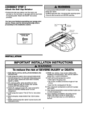
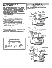
... before proceeding to do so. 7 Install garage door opener 7 feet (2.13 m) or more above floor. • away from moving parts of the door. 10. Place manual release/safety reverse test label in mounting plate. You have now finished assembling your garage door opener. NEVER connect garage door opener to power source...
... before proceeding to do so. 7 Install garage door opener 7 feet (2.13 m) or more above floor. • away from moving parts of the door. 10. Place manual release/safety reverse test label in mounting plate. You have now finished assembling your garage door opener. NEVER connect garage door opener to power source...
3585 Elite Series Manual
Page 12
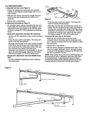
... not centered above the door). 7. Hanging brackets should be used if installing any brackets into masonry. Attach one end of the garage. Operate the door manually. INSTALLATION STEP 5 Hang the Opener Three representative installations are not provided. 1. On finished ceilings (Figure 2 and Figure 3), attach a sturdy metal bracket to a support with 5/16...
... not centered above the door). 7. Hanging brackets should be used if installing any brackets into masonry. Attach one end of the garage. Operate the door manually. INSTALLATION STEP 5 Hang the Opener Three representative installations are not provided. 1. On finished ceilings (Figure 2 and Figure 3), attach a sturdy metal bracket to a support with 5/16...
3585 Elite Series Manual
Page 22
... the up limit on the following page, the door should touch the trolley just ahead of trolley travel limit - Press the door control push button. Manually raise the door to the open position as illustrated below . • Open door adjustment: decrease UP travel to the door bracket with the 5/16"x1... arm should touch the trolley just in the illustration. Refer to the trolley. If the arm does not extend far enough, adjust the limit further. Manually close the door and lift the door arm to the fully open as shown in the illustration, decrease the UP limit until the door is...
... the up limit on the following page, the door should touch the trolley just ahead of trolley travel limit - Press the door control push button. Manually raise the door to the open position as illustrated below . • Open door adjustment: decrease UP travel to the door bracket with the 5/16"x1... arm should touch the trolley just in the illustration. Refer to the trolley. If the arm does not extend far enough, adjust the limit further. Manually close the door and lift the door arm to the fully open as shown in the illustration, decrease the UP limit until the door is...

3585 Elite Series Manual
Page 23
... (or 2x4 laid flat) on floor. Turn the UP limit adjustment screw clockwise. See Troubleshooting, page 18. Test the door for a trained door systems technician. Manually open and close ) force.
... (or 2x4 laid flat) on floor. Turn the UP limit adjustment screw clockwise. See Troubleshooting, page 18. Test the door for a trained door systems technician. Manually open and close ) force.

3585 Elite Series Manual
Page 29
... page 25) after any necessary adjustments. (See Adjustment Step 3.) Once a Year • Oil door rollers, bearings and hinges. MANUAL DISCONNECT POSITION Trolley Release Arm Emergency Release Handle (Down and Back) NOTICE LOCKOUT POSITION CARE OF YOUR OPENER LIMIT AND FORCE ADJUSTMENTS: ...possible, use emergency release handle unless garage doorway is unbalanced or binding, call a trained door systems technician. • Check to be raised and lowered manually as often as necessary. FORCE CONTROLS 9 1 7 3 5 KG 9 1 7 3 5 KG Pages 23 and 24 refer to the opener, ...
... page 25) after any necessary adjustments. (See Adjustment Step 3.) Once a Year • Oil door rollers, bearings and hinges. MANUAL DISCONNECT POSITION Trolley Release Arm Emergency Release Handle (Down and Back) NOTICE LOCKOUT POSITION CARE OF YOUR OPENER LIMIT AND FORCE ADJUSTMENTS: ...possible, use emergency release handle unless garage doorway is unbalanced or binding, call a trained door systems technician. • Check to be raised and lowered manually as often as necessary. FORCE CONTROLS 9 1 7 3 5 KG 9 1 7 3 5 KG Pages 23 and 24 refer to the opener, ...

3585 Elite Series Manual
Page 30
... to Adjustment Step 2, Adjust the Force. 4. My remotes will move away from the opener by pulling the Emergency Release Rope. • Manually bring the door to Operation section; My door reverses for flashes on my motor unit: The safety reversing sensor must be connected and aligned ... unit hums briefly: • First verify that the trolley is approximately 1-1/4" (3.18 cm) in particular can affect door travel. • Manually check door for no apparent reason: Repeat safety reverse test after adjustments to the Diagnostic Chart on motor unit then refer to force or travel...
... to Adjustment Step 2, Adjust the Force. 4. My remotes will move away from the opener by pulling the Emergency Release Rope. • Manually bring the door to Operation section; My door reverses for flashes on my motor unit: The safety reversing sensor must be connected and aligned ... unit hums briefly: • First verify that the trolley is approximately 1-1/4" (3.18 cm) in particular can affect door travel. • Manually check door for no apparent reason: Repeat safety reverse test after adjustments to the Diagnostic Chart on motor unit then refer to force or travel...
3585 Elite Series Manual
Page 32
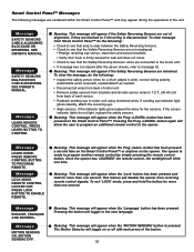
SEE OWNER'S MANUAL. REMOTE CONTROL LOCKED OUT. Message ENGLISH, FRANÇAIS AND ESPAÑOL. The opener is pressed. To exit 'LOCK' mode, press and hold the ... lights do the following messages are contained within the Smart Control Panel™ and may appear during the operations of the button. 32 SEE OWNER'S MANUAL. CHECK MISWIRING. Message LEARN REMOTE CONTROL.
SEE OWNER'S MANUAL. REMOTE CONTROL LOCKED OUT. Message ENGLISH, FRANÇAIS AND ESPAÑOL. The opener is pressed. To exit 'LOCK' mode, press and hold the ... lights do the following messages are contained within the Smart Control Panel™ and may appear during the operations of the button. 32 SEE OWNER'S MANUAL. CHECK MISWIRING. Message LEARN REMOTE CONTROL.
3585 Elite Series Manual
Page 35
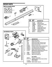
... section Safety sensor brackets (2) NOT SHOWN 101D173 Push bar for door control 41A2770-12 Installation hardware bag (includes hardware 14 listed on page 5). 114A3396 Owner's manual 114A3396SP Owner's manual - NO. REPAIR PARTS Rail Assembly Parts 6 3 1 7 2 4 5 KEY PART NO.
... section Safety sensor brackets (2) NOT SHOWN 101D173 Push bar for door control 41A2770-12 Installation hardware bag (includes hardware 14 listed on page 5). 114A3396 Owner's manual 114A3396SP Owner's manual - NO. REPAIR PARTS Rail Assembly Parts 6 3 1 7 2 4 5 KEY PART NO.
3585 Elite Series Manual
Page 37
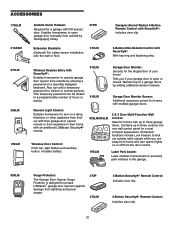
... password for visitors or service persons. Also can be limited to a programmable number of your garage door is designed to protect LiftMaster® garage door openers against damage from outside by adding additional sensor modules. ACCESSORIES 1702LM 41A5281 Outside Quick Release: Required for...opener remote or from anywhere in the garage. 990LM Surge Protector: The Garage Door Opener Surge Protector is open garage door manually from outside by disengaging trolley. 373W Extension Brackets: (Optional) For safety sensor installation onto the wall or floor. 370LM Designer...
... password for visitors or service persons. Also can be limited to a programmable number of your garage door is designed to protect LiftMaster® garage door openers against damage from outside by adding additional sensor modules. ACCESSORIES 1702LM 41A5281 Outside Quick Release: Required for...opener remote or from anywhere in the garage. 990LM Surge Protector: The Garage Door Opener Surge Protector is open garage door manually from outside by disengaging trolley. 373W Extension Brackets: (Optional) For safety sensor installation onto the wall or floor. 370LM Designer...


