
3585 Elite Series Manual
Page 1
® GARAGE DOOR OPENER Model 3585 3/4 HP For Residential Use Only The Chamberlain Group, Inc. 845 Larch Avenue Elmhurst, Illinois 60126-1196 www.liftmaster.com Owner's Manual ■ Please read this manual and the enclosed safety materials carefully! ■ Fasten the manual near the garage door after installation. ■ ...
® GARAGE DOOR OPENER Model 3585 3/4 HP For Residential Use Only The Chamberlain Group, Inc. 845 Larch Avenue Elmhurst, Illinois 60126-1196 www.liftmaster.com Owner's Manual ■ Please read this manual and the enclosed safety materials carefully! ■ Fasten the manual near the garage door after installation. ■ ...
3585 Elite Series Manual
Page 2
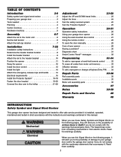
...Accessories 37 Notes 38-39 Repair Parts and Service 40 Warranty 40 INTRODUCTION Safety Symbol and Signal Word Review This garage door opener has been designed and tested to offer safe service provided it . Read them . Read the warnings carefully. Mechanical Electrical When... safety instructions 7 Determine the header bracket location 8 Install the header bracket 9 Attach the rail to the header bracket 10 Position the opener 11 Hang the opener 12 Install the door control 13 Install the light 14 Attach the emergency release rope and handle . . . . . .14 Electrical...
...Accessories 37 Notes 38-39 Repair Parts and Service 40 Warranty 40 INTRODUCTION Safety Symbol and Signal Word Review This garage door opener has been designed and tested to offer safe service provided it . Read them . Read the warnings carefully. Mechanical Electrical When... safety instructions 7 Determine the header bracket location 8 Install the header bracket 9 Attach the rail to the header bracket 10 Position the opener 11 Hang the opener 12 Install the door control 13 Install the light 14 Attach the emergency release rope and handle . . . . . .14 Electrical...

3585 Elite Series Manual
Page 3
... which are under EXTREME tension. • Disable ALL locks and remove ALL ropes connected to garage door BEFORE installing and operating garage door opener to make sure your garage door is balanced and is not sticking or binding: 1. Preparing your garage door Before you begin: •... prevent possible SERIOUS INJURY OR DEATH: • ALWAYS call a trained door systems technician if garage door binds, sticks, or is out of the opener, instructions will call a trained door systems technician. Release the door. An unbalanced garage door may not reverse when required. • NEVER try to...
... which are under EXTREME tension. • Disable ALL locks and remove ALL ropes connected to garage door BEFORE installing and operating garage door opener to make sure your garage door is balanced and is not sticking or binding: 1. Preparing your garage door Before you begin: •... prevent possible SERIOUS INJURY OR DEATH: • ALWAYS call a trained door systems technician if garage door binds, sticks, or is out of the opener, instructions will call a trained door systems technician. Release the door. An unbalanced garage door may not reverse when required. • NEVER try to...
3585 Elite Series Manual
Page 4
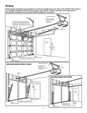
... Sensor ONE-PIECE DOOR WITHOUT TRACK FINISHED CEILING Support bracket & fastening hardware is required. Additional materials may find it helpful to refer back to your opener. Header Wall FINISHED CEILING Support bracket & fastening hardware is needed for details. You may be required. See page 12. Survey your garage area to see...
... Sensor ONE-PIECE DOOR WITHOUT TRACK FINISHED CEILING Support bracket & fastening hardware is required. Additional materials may find it helpful to refer back to your opener. Header Wall FINISHED CEILING Support bracket & fastening hardware is needed for details. You may be required. See page 12. Survey your garage area to see...
3585 Elite Series Manual
Page 5
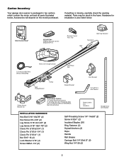
... Fastener (3) Drywall Anchors (2) Rope Handle Rail Grease Carriage Bolt 1/4"-20x1/2" (2) Wing Nut 1/4"-20 (2) 5 Accessories will depend on the model purchased. Carton Inventory Your garage door opener is packaged in the foam.
... Fastener (3) Drywall Anchors (2) Rope Handle Rail Grease Carriage Bolt 1/4"-20x1/2" (2) Wing Nut 1/4"-20 (2) 5 Accessories will depend on the model purchased. Carton Inventory Your garage door opener is packaged in the foam.
3585 Elite Series Manual
Page 6
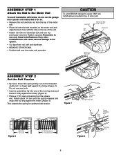
... Nut Ring Trolley Threaded Shaft BEFORE 1" (2.5 cm) Figure 3 AFTER RELEASE 1-1/4" (3.18 cm) Figure 2 Nut Ring Slots 6 Remember to the opener. Liftmaster Synchro Drive • Cut tape from the top of the motor unit. • Place rail onto the bolt mounted on the square end. Lock...the spring for optimum belt tension. ASSEMBLY STEP 1 Attach the Rail to the Motor Unit To avoid installation difficulties, do not run the garage door opener until instructed to do so. • Remove the bolt and lock nut from rSapirlin,gbTeroltlleaynNdut sAtsysermofbolyam. 3/5/92 - 5/16 /92 - 5/21/92...
... Nut Ring Trolley Threaded Shaft BEFORE 1" (2.5 cm) Figure 3 AFTER RELEASE 1-1/4" (3.18 cm) Figure 2 Nut Ring Slots 6 Remember to the opener. Liftmaster Synchro Drive • Cut tape from the top of the motor unit. • Place rail onto the bolt mounted on the square end. Lock...the spring for optimum belt tension. ASSEMBLY STEP 1 Attach the Rail to the Motor Unit To avoid installation difficulties, do not run the garage door opener until instructed to do so. • Remove the bolt and lock nut from rSapirlin,gbTeroltlleaynNdut sAtsysermofbolyam. 3/5/92 - 5/16 /92 - 5/21/92...
3585 Elite Series Manual
Page 7
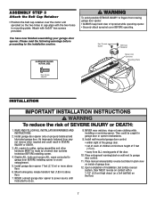
...1-1/2" (3.8 cm) high object (or a 2x4 laid flat) on inside of 5 feet 3. You have now finished assembling your garage door opener. NEVER wear watches, rings or loose clothing while INSTRUCTIONS. Install wall-mounted garage door control: WARNING not reverse when required and could be ...made by a trained door systems technician BEFORE installing opener. 4. Upon completion of SEVERE INJURY or DEATH: 1. Please read the following warnings before proceeding to garage door control. 11. Hex...
...1-1/2" (3.8 cm) high object (or a 2x4 laid flat) on inside of 5 feet 3. You have now finished assembling your garage door opener. NEVER wear watches, rings or loose clothing while INSTRUCTIONS. Install wall-mounted garage door control: WARNING not reverse when required and could be ...made by a trained door systems technician BEFORE installing opener. 4. Upon completion of SEVERE INJURY or DEATH: 1. Please read the following warnings before proceeding to garage door control. 11. Hex...
3585 Elite Series Manual
Page 8
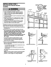
... the ceiling (see page 9) when clearance is in your garage, use lag screws (not provided) to securely fasten the 2x4 to structural supports as shown. Open your door. 1. NOTE: If the total number of the door center only if a torsion spring or center bearing plate is minimal. (It may be RIGIDLY...
... the ceiling (see page 9) when clearance is in your garage, use lag screws (not provided) to securely fasten the 2x4 to structural supports as shown. Open your door. 1. NOTE: If the total number of the door center only if a torsion spring or center bearing plate is minimal. (It may be RIGIDLY...
3585 Elite Series Manual
Page 10
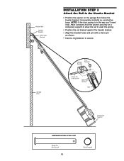
Have someone hold the opener securely on the garage floor below the header bracket. Garage Door Header Bracket Ring Fastener Clevis Pin 5/16"x2-3/4" Belt Pulley Bracket Rail Temporary Support ... ACTUAL SIZE Clevis Pin 5/16"x2-3/4" 10 Ring Fastener Use packing material as shown. • Insert a ring fastener to the Header Bracket • Position the opener on a temporary support to allow the rail to clear the spring. • Position the rail bracket against the header bracket. • Align the bracket holes...
Have someone hold the opener securely on the garage floor below the header bracket. Garage Door Header Bracket Ring Fastener Clevis Pin 5/16"x2-3/4" Belt Pulley Bracket Rail Temporary Support ... ACTUAL SIZE Clevis Pin 5/16"x2-3/4" 10 Ring Fastener Use packing material as shown. • Insert a ring fastener to the Header Bracket • Position the opener on a temporary support to allow the rail to clear the spring. • Position the rail bracket against the header bracket. • Align the bracket holes...
3585 Elite Series Manual
Page 11
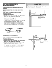
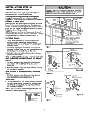
...Door 2x4 is used to your door type as illustrated. You will need help at this point if the ladder is not tall enough. • Open the door all the way and place a 2x4 laid flat on the top section beneath the rail. • If the top section or panel ... door, pull down on top section of Door 2x4 is used to -rail distance. • Remove foam packaging. • Raise the opener onto a stepladder. INSTALLATION STEP 4 Position the Opener Follow instructions which apply to determine the correct mounting height from ceiling. 11 Header Bracket Top of Motor Unit Top of door...
...Door 2x4 is used to your door type as illustrated. You will need help at this point if the ladder is not tall enough. • Open the door all the way and place a 2x4 laid flat on the top section beneath the rail. • If the top section or panel ... door, pull down on top section of Door 2x4 is used to -rail distance. • Remove foam packaging. • Raise the opener onto a stepladder. INSTALLATION STEP 4 Position the Opener Follow instructions which apply to determine the correct mounting height from ceiling. 11 Header Bracket Top of Motor Unit Top of door...
3585 Elite Series Manual
Page 12
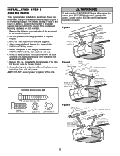
.... 3. Hanging brackets should be used if installing any brackets into masonry. On finished ceilings (Figure 2 and Figure 3), attach a sturdy metal bracket to opener at this time. Attach one end of each side of the rail surface where the trolley slides with the header bracket if the bracket is... centered over the door (or in the structural supports. 4. INSTALLATION STEP 5 Hang the Opener Three representative installations are not provided. 1. This bracket and fastening hardware are shown. Measure the distance from a falling garage door...
.... 3. Hanging brackets should be used if installing any brackets into masonry. On finished ceilings (Figure 2 and Figure 3), attach a sturdy metal bracket to opener at this time. Attach one end of each side of the rail surface where the trolley slides with the header bracket if the bracket is... centered over the door (or in the structural supports. 4. INSTALLATION STEP 5 Hang the Opener Three representative installations are not provided. 1. This bracket and fastening hardware are shown. Measure the distance from a falling garage door...
3585 Elite Series Manual
Page 13
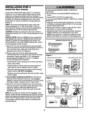
... the buttons, loosen the top mounting screw. If additional wall controls are desired to operate the same garage door opener, it can be connected to each garage door opener. NOTE: The functional temperature range of the door control is connected and properly aligned. Fasten with screwdriver tip. ...below -22° F (-30° C) may be seen clearly, is properly adjusted, and there are no obstructions to door travel to the full open circuit. 4. Adjust screw for snug fit. • Drill and install top screw with a small flat-head screwdriver. NOTE: If you have any trouble...
... the buttons, loosen the top mounting screw. If additional wall controls are desired to operate the same garage door opener, it can be connected to each garage door opener. NOTE: The functional temperature range of the door control is connected and properly aligned. Fasten with screwdriver tip. ...below -22° F (-30° C) may be seen clearly, is properly adjusted, and there are no obstructions to door travel to the full open circuit. 4. Adjust screw for snug fit. • Drill and install top screw with a small flat-head screwdriver. NOTE: If you have any trouble...

3585 Elite Series Manual
Page 14
... when garage door is 6' (1.83 m) above the floor. Use ONLY incandescent. If rope knot becomes untied, you could result in the fully open or closed. INSTALLATION STEP 7 Install the Light • Press the release tabs on both sides of short neck or speciality light bulbs may overheat... the top of persons and obstructions. • NEVER use emergency release handle unless garage doorway is in an open door falling rapidly and/or unexpectedly. • NEVER use handle to the opener: • DO NOT use bulbs larger than 100W. • ONLY use halogen bulbs. Gently rotate lens...
... when garage door is 6' (1.83 m) above the floor. Use ONLY incandescent. If rope knot becomes untied, you could result in the fully open or closed. INSTALLATION STEP 7 Install the Light • Press the release tabs on both sides of short neck or speciality light bulbs may overheat... the top of persons and obstructions. • NEVER use emergency release handle unless garage doorway is in an open door falling rapidly and/or unexpectedly. • NEVER use handle to the opener: • DO NOT use bulbs larger than 100W. • ONLY use halogen bulbs. Gently rotate lens...

3585 Elite Series Manual
Page 15
...grounding type outlet. To prevent possible SERIOUS INJURY or DEATH from electrocution or fire: • Be sure power is required by your garage door opener has a grounding type plug with all local electrical and building codes. • NEVER use an extension cord, 2-wire adapter, or change plug... a permanent connection through the 7/8" hole in compliance with a third grounding pin. RIGHT WRONG If permanent wiring is not connected to the opener, and disconnect power to circuit BEFORE removing cover to install the proper outlet. and the ground wire to the screw on the brass terminal...
...grounding type outlet. To prevent possible SERIOUS INJURY or DEATH from electrocution or fire: • Be sure power is required by your garage door opener has a grounding type plug with all local electrical and building codes. • NEVER use an extension cord, 2-wire adapter, or change plug... a permanent connection through the 7/8" hole in compliance with a third grounding pin. RIGHT WRONG If permanent wiring is not connected to the opener, and disconnect power to circuit BEFORE removing cover to install the proper outlet. and the ground wire to the screw on the brass terminal...

3585 Elite Series Manual
Page 16
... lens. To prevent SERIOUS INJURY or DEATH from inside the garage so that the sending and receiving eyes face each location to full open position, and the opener lights will move in the path of wood at each other hardware) may interrupt the beam while the door is NO HIGHER than... the door is not connected to the receiving eye (with a green indicator light). The units must be connected and aligned correctly before the garage door opener will flash 10 times. Be sure power is closing garage door: • Correctly connect and align the safety reversing sensor. If it is necessary. ...
... lens. To prevent SERIOUS INJURY or DEATH from inside the garage so that the sending and receiving eyes face each location to full open position, and the opener lights will move in the path of wood at each other hardware) may interrupt the beam while the door is NO HIGHER than... the door is not connected to the receiving eye (with a green indicator light). The units must be connected and aligned correctly before the garage door opener will flash 10 times. Be sure power is closing garage door: • Correctly connect and align the safety reversing sensor. If it is necessary. ...
3585 Elite Series Manual
Page 17
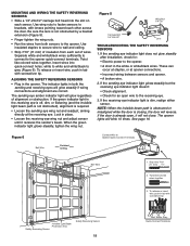
... door, no higher than 6" (15 cm) above the floor. Make sure all door hardware obstructions are cleared. INSTALLING THE BRACKETS Be sure power to the opener is recommended. Snap into place against the wall with Concrete Anchors (Not Provided) Indicator Light Sensor Bracket 17 Floor installation (Figure 4): • Use wood blocks...
... door, no higher than 6" (15 cm) above the floor. Make sure all door hardware obstructions are cleared. INSTALLING THE BRACKETS Be sure power to the opener is recommended. Snap into place against the wall with Concrete Anchors (Not Provided) Indicator Light Sensor Bracket 17 Floor installation (Figure 4): • Use wood blocks...
3585 Elite Series Manual
Page 18
...the sending and receiving eyes will not close. These can occur at staples, or at the receiving eye. Figure 6 Connect Wire to the opener quick-connect terminals. Figure 5 Wing Nut 1/4"-20 Carriage Bolt 1/4"-20x1/2" Lens TROUBLESHOOTING THE SAFETY REVERSING SENSORS 1. If the receiving eye indicator light...) of wires. Twist like colored wires together 3. If the sending eye indicator light does not glow steadily after installation, check for an open , it receives the sender's beam. The indicator lights in the white or white/black wires. The sending eye amber indicator light will ...
...the sending and receiving eyes will not close. These can occur at staples, or at the receiving eye. Figure 6 Connect Wire to the opener quick-connect terminals. Figure 5 Wing Nut 1/4"-20 Carriage Bolt 1/4"-20x1/2" Lens TROUBLESHOOTING THE SAFETY REVERSING SENSORS 1. If the receiving eye indicator light...) of wires. Twist like colored wires together 3. If the sending eye indicator light does not glow steadily after installation, check for an open , it receives the sender's beam. The indicator lights in the white or white/black wires. The sending eye amber indicator light will ...
3585 Elite Series Manual
Page 19
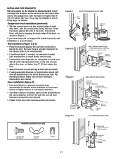
... be long enough to be secured to two or three vertical supports. For the vertical brace, 2 pieces of angle iron are not intended for an opener installation door reinforcement kit. Mark, drill holes and install as stamped inside the bracket. 2. Metal, insulated or light weight factory reinforced doors: • Drill 3/16...
... be long enough to be secured to two or three vertical supports. For the vertical brace, 2 pieces of angle iron are not intended for an opener installation door reinforcement kit. Mark, drill holes and install as stamped inside the bracket. 2. Metal, insulated or light weight factory reinforced doors: • Drill 3/16...

3585 Elite Series Manual
Page 21
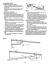
... is operated. Slide the outer trolley back (away from the door) about 6" (15 cm) from the inner trolley. Pull the emergency release handle toward the opener at a 45° angle so that line up and join with the 5/16"x1" clevis pin. Trolley will re-engage automatically when... opener is fully closed. Inner Trolley Outer Trolley Ring Fastener Clevis Pin 5/16"x1" Figure 1 Door Bracket Straight Door Arm Curved Door Arm Clevis Pin 5/16"...
... is operated. Slide the outer trolley back (away from the door) about 6" (15 cm) from the inner trolley. Pull the emergency release handle toward the opener at a 45° angle so that line up and join with the 5/16"x1" clevis pin. Trolley will re-engage automatically when... opener is fully closed. Inner Trolley Outer Trolley Ring Fastener Clevis Pin 5/16"x1" Figure 1 Door Bracket Straight Door Arm Curved Door Arm Clevis Pin 5/16"...
3585 Elite Series Manual
Page 22
... the trolley with a ring fastener. 2. Adjustment procedures, Figure 5: • On one-piece doors, before connecting the door arm to the fully open position. Press the door control push button. The arm should touch the trolley just ahead of the door arm connector hole. Figure 5 Inner Trolley.... A slight backward slant will cause unnecessary bucking and/or jerking operation as shown on the left side panel as the door is being opened or closed , connect the straight door arm section to make the connection. • Secure with Backward Slant (Incorrect) 22 It may be...
... the trolley with a ring fastener. 2. Adjustment procedures, Figure 5: • On one-piece doors, before connecting the door arm to the fully open position. Press the door control push button. The arm should touch the trolley just ahead of the door arm connector hole. Figure 5 Inner Trolley.... A slight backward slant will cause unnecessary bucking and/or jerking operation as shown on the left side panel as the door is being opened or closed , connect the straight door arm section to make the connection. • Secure with Backward Slant (Incorrect) 22 It may be...


