
3255 Manual
Page 1
® GARAGE DOOR OPENER Models 3245 1/3 HP 3255 1/2 HP 3255-2 1/2 HP For Residential Use Only The Chamberlain Group, Inc. 845 Larch Avenue Elmhurst, Illinois 60126-1196 www.liftmaster.com Owner's Manual ■ Please read this manual and the enclosed safety materials carefully! ■ Fasten the manual near the garage door after installation. ■ ...
® GARAGE DOOR OPENER Models 3245 1/3 HP 3255 1/2 HP 3255-2 1/2 HP For Residential Use Only The Chamberlain Group, Inc. 845 Larch Avenue Elmhurst, Illinois 60126-1196 www.liftmaster.com Owner's Manual ■ Please read this manual and the enclosed safety materials carefully! ■ Fasten the manual near the garage door after installation. ■ ...
3255 Manual
Page 2
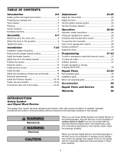
... 7 Determine the header bracket location 8 Install the header bracket 9 Attach the rail to the header bracket 10 Position the opener 11 Hang the opener 12 Install the door control 13 Install the light 14 Attach the emergency release rope and handle 14 Electrical requirements 15 Install ... pages, they will alert you to the possibility of damage to the possibility of your garage door and/or the garage door opener if you do not comply with the instructions and warnings contained in strict accordance with the cautionary statements that accompany them carefully. ...
... 7 Determine the header bracket location 8 Install the header bracket 9 Attach the rail to the header bracket 10 Position the opener 11 Hang the opener 12 Install the door control 13 Install the light 14 Attach the emergency release rope and handle 14 Electrical requirements 15 Install ... pages, they will alert you to the possibility of damage to the possibility of your garage door and/or the garage door opener if you do not comply with the instructions and warnings contained in strict accordance with the cautionary statements that accompany them carefully. ...
3255 Manual
Page 3
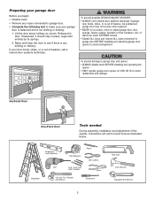
...under EXTREME tension. • Disable ALL locks and remove ALL ropes connected to garage door BEFORE installing and operating garage door opener to avoid malfunction and damage. If your garage door is balanced and is not sticking or binding: 1. To prevent damage to garage...To prevent possible SERIOUS INJURY OR DEATH: • ALWAYS call a trained door systems technician if garage door binds, sticks, or is out of the opener, instructions will call a trained door systems technician. Carpenter's Level (Optional) 12 Tape Measure Pencil Wire Cutters Drill 3/16", 5/16" and 5/32"...
...under EXTREME tension. • Disable ALL locks and remove ALL ropes connected to garage door BEFORE installing and operating garage door opener to avoid malfunction and damage. If your garage door is balanced and is not sticking or binding: 1. To prevent damage to garage...To prevent possible SERIOUS INJURY OR DEATH: • ALWAYS call a trained door systems technician if garage door binds, sticks, or is out of the opener, instructions will call a trained door systems technician. Carpenter's Level (Optional) 12 Tape Measure Pencil Wire Cutters Drill 3/16", 5/16" and 5/32"...
3255 Manual
Page 4
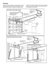
... is required. Planning Identify the type and height of door must not exceed 1/4" (6 mm). Additional materials may find it helpful to refer back to your opener. SECTIONAL DOOR INSTALLATION Horizontal and vertical reinforcement is closed. See page 12. Safety Reversing Sensor Safety Reversing Sensor Gap between floor and bottom of your...
... is required. Planning Identify the type and height of door must not exceed 1/4" (6 mm). Additional materials may find it helpful to refer back to your opener. SECTIONAL DOOR INSTALLATION Horizontal and vertical reinforcement is closed. See page 12. Safety Reversing Sensor Safety Reversing Sensor Gap between floor and bottom of your...
3255 Manual
Page 5
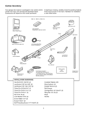
contain the motor unit and all parts illustrated below . 3245 (1), 3255 (1), 3255-2 (2) LOCK LIGHT Multi-Function Door Control Panel : SECURITY ® Single-Button Remote Control Remote Control Visor Clip Chain Sprocket Cover Styrofoam Motor Unit with 2-Conductor ... the model purchased. Parts may be stuck in two cartons which If anything is missing, carefully check the packing material. Carton Inventory Your garage door opener is packaged in the foam.
contain the motor unit and all parts illustrated below . 3245 (1), 3255 (1), 3255-2 (2) LOCK LIGHT Multi-Function Door Control Panel : SECURITY ® Single-Button Remote Control Remote Control Visor Clip Chain Sprocket Cover Styrofoam Motor Unit with 2-Conductor ... the model purchased. Parts may be stuck in two cartons which If anything is missing, carefully check the packing material. Carton Inventory Your garage door opener is packaged in the foam.
3255 Manual
Page 6
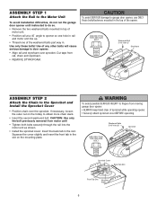
...; Securely attach sprocket cover BEFORE operating. Use of the washered bolts part way in. Cut tape from moving garage door opener: • ALWAYS keep hand clear of the opener. USE ONLY THIS TYPE AND SIZE BOLT Rail Hole Washered Bolt 5/16"-18x1/2" Styrofoam ASSEMBLY STEP 2 Attach the Chain to the ... the slot. Use only these bolts! ASSEMBLY STEP 1 Attach the Rail to the Motor Unit To avoid installation difficulties, do not run the garage door opener until instructed to do so. • Remove the two washered bolts mounted in top of motor unit. • Position rail at a 45˚ angle...
...; Securely attach sprocket cover BEFORE operating. Use of the washered bolts part way in. Cut tape from moving garage door opener: • ALWAYS keep hand clear of the opener. USE ONLY THIS TYPE AND SIZE BOLT Rail Hole Washered Bolt 5/16"-18x1/2" Styrofoam ASSEMBLY STEP 2 Attach the Chain to the ... the slot. Use only these bolts! ASSEMBLY STEP 1 Attach the Rail to the Motor Unit To avoid installation difficulties, do not run the garage door opener until instructed to do so. • Remove the two washered bolts mounted in top of motor unit. • Position rail at a 45˚ angle...
3255 Manual
Page 7
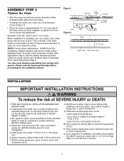
...Step 3. Mount emergency release handle 6 feet (1.83 m) above floor. 6. Upon completion of Rail You have now finished assembling your garage door opener. READ AND FOLLOW ALL INSTALLATION WARNINGS AND INSTRUCTIONS. 2. ASSEMBLY STEP 3 Tighten the Chain • Spin the inner nut and lock washer ...tighten the inner nut to garage door control. 11. ALL repairs to the position shown in garage door or opener mechanisms. 9. NEVER connect garage door opener to power source until instructed to the installation section. Install wall-mounted garage door control: • within sight...
...Step 3. Mount emergency release handle 6 feet (1.83 m) above floor. 6. Upon completion of Rail You have now finished assembling your garage door opener. READ AND FOLLOW ALL INSTALLATION WARNINGS AND INSTRUCTIONS. 2. ASSEMBLY STEP 3 Tighten the Chain • Spin the inner nut and lock washer ...tighten the inner nut to garage door control. 11. ALL repairs to the position shown in garage door or opener mechanisms. 9. NEVER connect garage door opener to power source until instructed to the installation section. Install wall-mounted garage door control: • within sight...
3255 Manual
Page 8
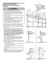
Header Wall Unfinished Ceiling 2x4 Vertical Centerline of balance. Extend the line onto the header wall above the door. Open your door to the highest point of travel clearance for the top edge of the garage door. 2. Header Wall 2" (5 cm) Track Highest Point of Travel ...
Header Wall Unfinished Ceiling 2x4 Vertical Centerline of balance. Extend the line onto the header wall above the door. Open your door to the highest point of travel clearance for the top edge of the garage door. 2. Header Wall 2" (5 cm) Track Highest Point of Travel ...
3255 Manual
Page 10
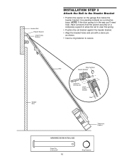
...5/16"x2-3/4" Chain Pulley Bracket Rail Temporary Support HARDWARE SHOWN ACTUAL SIZE Clevis Pin 5/16"x2-3/4" 10 Ring Fastener Have someone hold the opener securely on the garage floor below the header bracket. NOTE: If the door spring is in the way you'll need help. Header Wall... INSTALLATION STEP 3 Attach the Rail to secure. Use packing material as shown. • Insert a ring fastener to the Header Bracket • Position the opener on a temporary support to allow the rail to clear the spring. • Position the rail bracket against the header bracket. • Align the bracket...
...5/16"x2-3/4" Chain Pulley Bracket Rail Temporary Support HARDWARE SHOWN ACTUAL SIZE Clevis Pin 5/16"x2-3/4" 10 Ring Fastener Have someone hold the opener securely on the garage floor below the header bracket. NOTE: If the door spring is in the way you'll need help. Header Wall... INSTALLATION STEP 3 Attach the Rail to secure. Use packing material as shown. • Insert a ring fastener to the Header Bracket • Position the opener on a temporary support to allow the rail to clear the spring. • Position the rail bracket against the header bracket. • Align the bracket...
3255 Manual
Page 11
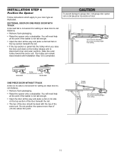
...DOOR WITHOUT TRACK A 2x4 on top section of Door 2x4 is completed. INSTALLATION STEP 4 Position the Opener Follow instructions which apply to -rail distance. • Remove foam packaging. • Raise the opener onto a stepladder. Rail Door 2x4 is convenient for setting an ideal door-to your door type ...as illustrated. Header Bracket Top of door. To prevent damage to garage door, rest garage door opener rail on 2x4 placed on its side on the trolley release arm to disconnect inner and outer sections. The trolley can remain disconnected ...
...DOOR WITHOUT TRACK A 2x4 on top section of Door 2x4 is completed. INSTALLATION STEP 4 Position the Opener Follow instructions which apply to -rail distance. • Remove foam packaging. • Raise the opener onto a stepladder. Rail Door 2x4 is convenient for setting an ideal door-to your door type ...as illustrated. Header Bracket Top of door. To prevent damage to garage door, rest garage door opener rail on 2x4 placed on its side on the trolley release arm to disconnect inner and outer sections. The trolley can remain disconnected ...
3255 Manual
Page 12
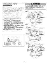
...16" Nut 5/16"-18 FINISHED CEILING (Not Provided) Bolt 5/16"-18x7/8" Lock Washer 5/16" Nut 5/16"-18 12 Check to opener at this time. Operate the door manually. Yours may be used if installing any brackets into masonry. Concrete anchors MUST be different. ...trolley slides with 5/16"-18x1-7/8" lag screws. 5. Hanging brackets should be angled (Figure 1) to structural supports before installing the opener. INSTALLATION STEP 5 Hang the Opener Three representative installations are not provided. 1. Drill 3/16" pilot holes in line with 5/16"-18x7/8" hex bolts, lock washers ...
...16" Nut 5/16"-18 FINISHED CEILING (Not Provided) Bolt 5/16"-18x7/8" Lock Washer 5/16" Nut 5/16"-18 12 Check to opener at this time. Operate the door manually. Yours may be used if installing any brackets into masonry. Concrete anchors MUST be different. ...trolley slides with 5/16"-18x1-7/8" lag screws. 5. Hanging brackets should be angled (Figure 1) to structural supports before installing the opener. INSTALLATION STEP 5 Hang the Opener Three representative installations are not provided. 1. Drill 3/16" pilot holes in line with 5/16"-18x7/8" hex bolts, lock washers ...
3255 Manual
Page 13
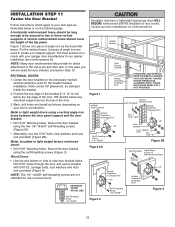
... will not return to the close position until the sensor beam is properly adjusted, and there are no obstructions to door travel to the full open circuit. 4. Strip 7/16" (11 mm) of insulation from one end of bell wire and connect to the two screw terminals on page 16. Use ... box (Figure 2). Remove cover by color: white wire to 2 and white/red wire to the 1 (Figure 3). 2. NOTE: DO NOT connect the power and operate the opener at this time. Strip 7/16" (11 mm) of insulation from electrocution: • Be sure power is NOT connected BEFORE installing door control. • Connect ONLY...
... will not return to the close position until the sensor beam is properly adjusted, and there are no obstructions to door travel to the full open circuit. 4. Strip 7/16" (11 mm) of insulation from one end of bell wire and connect to the two screw terminals on page 16. Use ... box (Figure 2). Remove cover by color: white wire to 2 and white/red wire to the 1 (Figure 3). 2. NOTE: DO NOT connect the power and operate the opener at this time. Strip 7/16" (11 mm) of insulation from electrocution: • Be sure power is NOT connected BEFORE installing door control. • Connect ONLY...
3255 Manual
Page 14
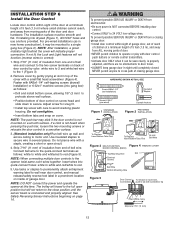
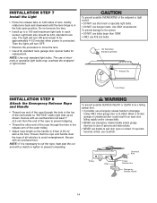
...will turn ON and remain lit for replacement. Secure with a match or lighter to close the lens. • Use A19, standard neck garage door opener bulbs for approximately 4-1/2 minutes when power is CLOSED. Ensure that the rope and handle clear the tops of all vehicles to a 100 watt maximum ... arm of the outer trolley. • Adjust rope length so the handle is clear of persons and obstructions. • NEVER use handle to the opener: • DO NOT use bulbs larger than 100W. • ONLY use emergency release handle to disengage trolley ONLY when garage door is connected. To...
...will turn ON and remain lit for replacement. Secure with a match or lighter to close the lens. • Use A19, standard neck garage door opener bulbs for approximately 4-1/2 minutes when power is CLOSED. Ensure that the rope and handle clear the tops of all vehicles to a 100 watt maximum ... arm of the outer trolley. • Adjust rope length so the handle is clear of persons and obstructions. • NEVER use handle to the opener: • DO NOT use bulbs larger than 100W. • ONLY use emergency release handle to disengage trolley ONLY when garage door is connected. To...
3255 Manual
Page 15
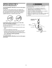
... fit into the outlet you have, contact a qualified electrician to the following procedure. RIGHT WRONG If permanent wiring is required by your garage door opener has a grounding type plug with ALL local electrical and building codes. • NEVER use an extension cord, 2-wire adapter, or change plug ...terminal; To make it fit outlet. PERMANENT WIRING CONNECTION Ground Tab Green Ground Screw Ground Wire Black Wire White Wire Black Wire 15 The opener must be in the top of electric shock, your local code, refer to install the proper outlet. To reduce the risk of the...
... fit into the outlet you have, contact a qualified electrician to the following procedure. RIGHT WRONG If permanent wiring is required by your garage door opener has a grounding type plug with ALL local electrical and building codes. • NEVER use an extension cord, 2-wire adapter, or change plug ...terminal; To make it fit outlet. PERMANENT WIRING CONNECTION Ground Tab Green Ground Screw Ground Wire Black Wire White Wire Black Wire 15 The opener must be in the top of electric shock, your local code, refer to install the proper outlet. To reduce the risk of the...
3255 Manual
Page 16
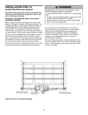
...15 cm) above the floor. above floor The sending eye (with an amber indicator light) transmits an invisible light beam to the garage door opener BEFORE installing the safety reversing sensor. If it is not connected to the receiving eye (with a green indicator light). above floor Invisible Light ... and aligned, the sensor will move in masonry if repositioning is closing. Either can be connected and aligned correctly before the garage door opener will detect an obstacle in masonry construction, add a piece of wood at each other hardware) may interrupt the beam while the door is...
...15 cm) above the floor. above floor The sending eye (with an amber indicator light) transmits an invisible light beam to the garage door opener BEFORE installing the safety reversing sensor. If it is not connected to the receiving eye (with a green indicator light). above floor Invisible Light ... and aligned, the sensor will move in masonry if repositioning is closing. Either can be connected and aligned correctly before the garage door opener will detect an obstacle in masonry construction, add a piece of wood at each other hardware) may interrupt the beam while the door is...
3255 Manual
Page 17
... to be unobstructed. • If additional depth is disconnected. Make sure all door hardware obstructions are cleared. INSTALLING THE BRACKETS Be sure power to the opener is needed, an extension bracket (see Accessories) to elevate sensor brackets so the lenses will be no higher than 6" (15 cm) above the floor. •...
... to be unobstructed. • If additional depth is disconnected. Make sure all door hardware obstructions are cleared. INSTALLING THE BRACKETS Be sure power to the opener is needed, an extension bracket (see Accessories) to elevate sensor brackets so the lenses will be no higher than 6" (15 cm) above the floor. •...

3255 Manual
Page 18
...the receiving eye. If the door is required. • Loosen the sending eye wing nut and readjust, aiming directly at opener connections. • Incorrect wiring between sensors and opener. • A broken wire. 2. MOUNTING AND WIRING THE SAFETY REVERSING SENSORS • Slide a 1/4"-20x1/2" carriage bolt ...into quick-connect holes: white to white and white/black to grey (Figure 6). Use insulated staples to secure wire to the opener quick-connect terminals. If the green indicator light in tab with lenses pointing toward each set of insulation from both the sending and...
...the receiving eye. If the door is required. • Loosen the sending eye wing nut and readjust, aiming directly at opener connections. • Incorrect wiring between sensors and opener. • A broken wire. 2. MOUNTING AND WIRING THE SAFETY REVERSING SENSORS • Slide a 1/4"-20x1/2" carriage bolt ...into quick-connect holes: white to white and white/black to grey (Figure 6). Use insulated staples to secure wire to the opener quick-connect terminals. If the green indicator light in tab with lenses pointing toward each set of insulation from both the sending and...
3255 Manual
Page 19
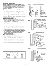
... bracket holes. Note correct UP placement, as the horizontal brace. Drill 5/16" holes through the door and secure bracket with your door manufacturer for an opener installation door reinforcement kit. HARDWARE SHOWN ACTUAL SIZE Self-Threading Screw 1/4"-14x5/8" Fiberglass, aluminum or lightweight steel garage doors WILL REQUIRE reinforcement BEFORE installation of...
... bracket holes. Note correct UP placement, as the horizontal brace. Drill 5/16" holes through the door and secure bracket with your door manufacturer for an opener installation door reinforcement kit. HARDWARE SHOWN ACTUAL SIZE Self-Threading Screw 1/4"-14x5/8" Fiberglass, aluminum or lightweight steel garage doors WILL REQUIRE reinforcement BEFORE installation of...
3255 Manual
Page 21
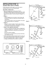
... arm sections together. Select holes as far apart as shown in Figures 1, 2 and 3. • Figure 1: - Trolley will re-engage automatically when opener is horizontal. Find two pairs of holes that the trolley release arm is operated. Slide the outer trolley back (away from the door) about 6" (...8226; Make sure garage door is fully closed. Reconnect to trolley with bolts, lock washers and nuts. • Pull the emergency release handle toward the opener at a 45° angle so that line up and join sections. Cut about 2" (5 cm) as possible to increase door arm rigidity. •...
... arm sections together. Select holes as far apart as shown in Figures 1, 2 and 3. • Figure 1: - Trolley will re-engage automatically when opener is horizontal. Find two pairs of holes that the trolley release arm is operated. Slide the outer trolley back (away from the door) about 6" (...8226; Make sure garage door is fully closed. Reconnect to trolley with bolts, lock washers and nuts. • Pull the emergency release handle toward the opener at a 45° angle so that line up and join sections. Cut about 2" (5 cm) as possible to increase door arm rigidity. •...

3255 Manual
Page 22
... limit further. Refer to the trolley. A slight backward slant will cause unnecessary bucking and/or jerking operation as illustrated below . • Open door adjustment: decrease UP travel limit - Manually close the door and lift the door arm to the fully closed position. - Adjustment procedures,... door arm sections together to the longest possible length (with a 2 or 3 hole overlap). • With the door closed from the fully open position. - Turn the DOWN limit adjustment screw clockwise 4 complete turns. The trolley will travel limit - One full turn equals 2" (5 cm)...
... limit further. Refer to the trolley. A slight backward slant will cause unnecessary bucking and/or jerking operation as illustrated below . • Open door adjustment: decrease UP travel limit - Manually close the door and lift the door arm to the fully closed position. - Adjustment procedures,... door arm sections together to the longest possible length (with a 2 or 3 hole overlap). • With the door closed from the fully open position. - Turn the DOWN limit adjustment screw clockwise 4 complete turns. The trolley will travel limit - One full turn equals 2" (5 cm)...


