
3255 Manual
Page 1
® GARAGE DOOR OPENER Models 3245 1/3 HP 3255 1/2 HP 3255-2 1/2 HP For Residential Use Only The Chamberlain Group, Inc. 845 Larch Avenue Elmhurst, Illinois 60126-1196 www.liftmaster.com Owner's Manual ■ Please read this manual and the enclosed safety materials carefully! ■ Fasten the manual near the garage door after installation. ■ The door WILL NOT CLOSE unless...
® GARAGE DOOR OPENER Models 3245 1/3 HP 3255 1/2 HP 3255-2 1/2 HP For Residential Use Only The Chamberlain Group, Inc. 845 Larch Avenue Elmhurst, Illinois 60126-1196 www.liftmaster.com Owner's Manual ■ Please read this manual and the enclosed safety materials carefully! ■ Fasten the manual near the garage door after installation. ■ The door WILL NOT CLOSE unless...
3255 Manual
Page 2
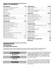
...not comply with the cautionary statements that accompany them carefully. 2 TABLE OF CONTENTS Introduction 2-5 Safety symbol and signal word review 2 Preparing your garage door 3 Tools needed 3 Planning 4 Carton inventory 5 Hardware inventory 5 Assembly 6-7 Attach the rail to the motor unit 6 Attach the chain to...25 Operation 26-30 Operation safety instructions 26 Using your garage door opener 26 Using the wall-mounted door control 27 To open the door manually 27 Care of your garage door and/or the garage door opener if you do not comply with the warnings that ...
...not comply with the cautionary statements that accompany them carefully. 2 TABLE OF CONTENTS Introduction 2-5 Safety symbol and signal word review 2 Preparing your garage door 3 Tools needed 3 Planning 4 Carton inventory 5 Hardware inventory 5 Assembly 6-7 Attach the rail to the motor unit 6 Attach the chain to...25 Operation 26-30 Operation safety instructions 26 Using your garage door opener 26 Using the wall-mounted door control 27 To open the door manually 27 Care of your garage door and/or the garage door opener if you do not comply with the warnings that ...
3255 Manual
Page 3
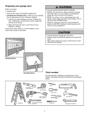
...installing and operating the opener. • ONLY operate garage door opener at 120V, 60 Hz to avoid entanglement. An unbalanced garage door may not reverse when required. • NEVER try to loosen, move or adjust garage door, door springs, cables, pulleys, brackets or their hardware, ALL... and adjustment of which are under EXTREME tension. • Disable ALL locks and remove ALL ropes connected to garage door BEFORE installing and operating garage door opener to avoid malfunction and damage. Carpenter's Level (Optional) 12 Tape Measure Pencil Wire Cutters Drill 3/16",...
...installing and operating the opener. • ONLY operate garage door opener at 120V, 60 Hz to avoid entanglement. An unbalanced garage door may not reverse when required. • NEVER try to loosen, move or adjust garage door, door springs, cables, pulleys, brackets or their hardware, ALL... and adjustment of which are under EXTREME tension. • Disable ALL locks and remove ALL ropes connected to garage door BEFORE installing and operating garage door opener to avoid malfunction and damage. Carpenter's Level (Optional) 12 Tape Measure Pencil Wire Cutters Drill 3/16",...
3255 Manual
Page 4
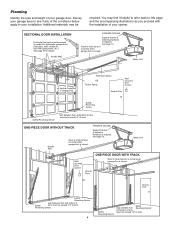
... the installation of your opener. You may be required. Slack in chain tension is normal when garage door is closed . Motor Unit Vertical Centerline of Garage Door Extension Spring OR Torsion Spring Wallmounted Door Control Access Door --- --- -- FINISHED CEILING Support bracket & fastening hardware is required. See page 12. Safety Reversing Sensor Safety Reversing Sensor Gap between...
... the installation of your opener. You may be required. Slack in chain tension is normal when garage door is closed . Motor Unit Vertical Centerline of Garage Door Extension Spring OR Torsion Spring Wallmounted Door Control Access Door --- --- -- FINISHED CEILING Support bracket & fastening hardware is required. See page 12. Safety Reversing Sensor Safety Reversing Sensor Gap between...
3255 Manual
Page 5
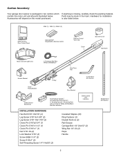
...2 Conductor Bell Wire White & White/Red? contain the motor unit and all parts illustrated below . 3245 (1), 3255 (1), 3255-2 (2) LOCK LIGHT Multi-Function Door Control Panel : SECURITY ® Single-Button Remote Control Remote Control Visor Clip Chain Sprocket Cover Styrofoam Motor Unit ...Grease Carriage Bolt 1/4"-20x1/2" (2) Wing Nut 1/4"-20 (2) Rope Handle 5 Straight Door Arm Section Parts may be stuck in two cartons which If anything is also listed below . Carton Inventory Your garage door opener is packaged in the foam. is missing, carefully check the packing material....
...2 Conductor Bell Wire White & White/Red? contain the motor unit and all parts illustrated below . 3245 (1), 3255 (1), 3255-2 (2) LOCK LIGHT Multi-Function Door Control Panel : SECURITY ® Single-Button Remote Control Remote Control Visor Clip Chain Sprocket Cover Styrofoam Motor Unit ...Grease Carriage Bolt 1/4"-20x1/2" (2) Wing Nut 1/4"-20 (2) Rope Handle 5 Straight Door Arm Section Parts may be stuck in two cartons which If anything is also listed below . Carton Inventory Your garage door opener is packaged in the foam. is missing, carefully check the packing material....
3255 Manual
Page 6
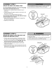
.... USE ONLY THIS TYPE AND SIZE BOLT Rail Hole Washered Bolt 5/16"-18x1/2" Styrofoam ASSEMBLY STEP 2 Attach the Chain to fingers from moving garage door opener: • ALWAYS keep hand clear of sprocket while operating opener. • Securely attach sprocket cover BEFORE operating. To avoid possible SERIOUS ... the outer nut on the mounting plate. ASSEMBLY STEP 1 Attach the Rail to the Motor Unit To avoid installation difficulties, do not run the garage door opener until instructed to do so. • Remove the two washered bolts mounted in top of motor unit. • Position rail at a ...
.... USE ONLY THIS TYPE AND SIZE BOLT Rail Hole Washered Bolt 5/16"-18x1/2" Styrofoam ASSEMBLY STEP 2 Attach the Chain to fingers from moving garage door opener: • ALWAYS keep hand clear of sprocket while operating opener. • Securely attach sprocket cover BEFORE operating. To avoid possible SERIOUS ... the outer nut on the mounting plate. ASSEMBLY STEP 1 Attach the Rail to the Motor Unit To avoid installation difficulties, do not run the garage door opener until instructed to do so. • Remove the two washered bolts mounted in top of motor unit. • Position rail at a ...
3255 Manual
Page 7
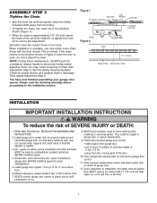
...Then repeat Adjustment Step 3. Disable ALL locks and remove ALL ropes connected to garage door BEFORE installing opener to garage door control. 11. Install wall-mounted garage door control: • within sight of the garage door. • out of reach of children at its midpoint, re-tighten the ...wear watches, rings or loose clothing while installing or servicing opener. ALL repairs to the position shown in plain view on inside of garage door. 12. They could result in the direction shown (Figure 1). When installation is complete, you may notice some chain droop with a...
...Then repeat Adjustment Step 3. Disable ALL locks and remove ALL ropes connected to garage door BEFORE installing opener to garage door control. 11. Install wall-mounted garage door control: • within sight of the garage door. • out of reach of children at its midpoint, re-tighten the ...wear watches, rings or loose clothing while installing or servicing opener. ALL repairs to the position shown in plain view on inside of garage door. 12. They could result in the direction shown (Figure 1). When installation is complete, you may notice some chain droop with a...
3255 Manual
Page 8
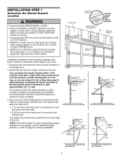
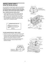
... bracket over drywall. • Concrete anchors MUST be used if mounting header bracket or 2x4 into masonry. • NEVER try to loosen, move or adjust garage door, springs, cables, pulleys, brackets, or their hardware, ALL of which apply to structural support on the header wall above the high point: • 2" (5 cm) above...
... bracket over drywall. • Concrete anchors MUST be used if mounting header bracket or 2x4 into masonry. • NEVER try to loosen, move or adjust garage door, springs, cables, pulleys, brackets, or their hardware, ALL of which apply to structural support on the header wall above the high point: • 2" (5 cm) above...
3255 Manual
Page 9
...Header Wall 2x4 Structural Support Header Bracket CEILING MOUNT ONLY UP Vertical Centerline of Garage Door Lag Screws 5/16"-9x1-5/8" Door Spring Horizontal Line Highest Point of Garage Door Travel Garage Door Vertical Centerline of bracket holes (do not use lag screws to mount the ...You must use concrete anchors (not provided). Finished Ceiling - Header Bracket Vertical Centerline of Garage Door UP Lag Screws 5/16"-9x1-5/8" Garage Door Header Wall Vertical Centerline of Garage Door 9 Follow the instructions which will work best for ceiling mount). Drill 3/16" pilot ...
...Header Wall 2x4 Structural Support Header Bracket CEILING MOUNT ONLY UP Vertical Centerline of Garage Door Lag Screws 5/16"-9x1-5/8" Door Spring Horizontal Line Highest Point of Garage Door Travel Garage Door Vertical Centerline of bracket holes (do not use lag screws to mount the ...You must use concrete anchors (not provided). Finished Ceiling - Header Bracket Vertical Centerline of Garage Door UP Lag Screws 5/16"-9x1-5/8" Garage Door Header Wall Vertical Centerline of Garage Door 9 Follow the instructions which will work best for ceiling mount). Drill 3/16" pilot ...
3255 Manual
Page 10
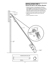
Garage Door Ring Fastener Rail Header Bracket Clevis Pin 5/16"x2-3/4" Chain Pulley Bracket Rail Temporary Support HARDWARE SHOWN ACTUAL SIZE Clevis Pin 5/16"x2-3/4" 10 Ring .... • Align the bracket holes and join with a clevis pin as a protective base. Have someone hold the opener securely on the garage floor below the header bracket. NOTE: If the door spring is in the way you'll need help. Header Wall Header Bracket Chain Pulley Bracket INSTALLATION STEP 3 Attach the Rail...
Garage Door Ring Fastener Rail Header Bracket Clevis Pin 5/16"x2-3/4" Chain Pulley Bracket Rail Temporary Support HARDWARE SHOWN ACTUAL SIZE Clevis Pin 5/16"x2-3/4" 10 Ring .... • Align the bracket holes and join with a clevis pin as a protective base. Have someone hold the opener securely on the garage floor below the header bracket. NOTE: If the door spring is in the way you'll need help. Header Wall Header Bracket Chain Pulley Bracket INSTALLATION STEP 3 Attach the Rail...
3255 Manual
Page 11
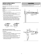
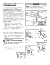
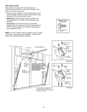
INSTALLATION STEP 4 Position the Opener Follow instructions which apply to garage door, rest garage door opener rail on 2x4 placed on top section of the motor unit. SECTIONAL DOOR OR ONE-PIECE DOOR WITH TRACK A 2x4 laid flat is convenient for setting an ideal door-to determine the correct mounting height from ceiling. 11 Slide ...used to disconnect inner and outer sections. You will need help at this point if the ladder is not tall enough. • Open the door all the way and place a 2x4 laid flat on the top section beneath the rail. • If the top section or panel hits ...
INSTALLATION STEP 4 Position the Opener Follow instructions which apply to garage door, rest garage door opener rail on 2x4 placed on top section of the motor unit. SECTIONAL DOOR OR ONE-PIECE DOOR WITH TRACK A 2x4 laid flat is convenient for setting an ideal door-to determine the correct mounting height from ceiling. 11 Slide ...used to disconnect inner and outer sections. You will need help at this point if the ladder is not tall enough. • Open the door all the way and place a 2x4 laid flat on the top section beneath the rail. • If the top section or panel hits ...
3255 Manual
Page 12
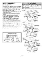
...to provide rigid support. Fasten the opener to structural supports before installing the opener. Yours may be different. Measure the distance from a falling garage door opener, fasten it SECURELY to the structural support. 2. Attach one end of each side of the motor unit to structural supports of the... CEILING (Not Provided) Bolt 5/16"-18x7/8" Lock Washer 5/16" Nut 5/16"-18 12 Grease the top and underside of the garage. Remove the 2x4. If the door hits the rail, raise the header bracket. 8. On finished ceilings (Figure 2 and Figure 3), attach a sturdy metal bracket to the...
...to provide rigid support. Fasten the opener to structural supports before installing the opener. Yours may be different. Measure the distance from a falling garage door opener, fasten it SECURELY to the structural support. 2. Attach one end of each side of the motor unit to structural supports of the... CEILING (Not Provided) Bolt 5/16"-18x7/8" Lock Washer 5/16" Nut 5/16"-18 12 Grease the top and underside of the garage. Remove the 2x4. If the door hits the rail, raise the header bracket. 8. On finished ceilings (Figure 2 and Figure 3), attach a sturdy metal bracket to the...
3255 Manual
Page 13
... and properly aligned. The trolley will not return to the 1 (Figure 3). 2. To prevent possible SERIOUS INJURY or DEATH from a closing garage door. HARDWARE SHOWN ACTUAL SIZE Screw 6ABx1-1/4" (std installation) Insulated Staples Screw 6-32x1" (pre-wired) Figure 1 STANDARD INSTALLATION Drywall Anchors PRE-... screw for snug fit. • Install top screw with care to red (Figure 5). INSTALLATION STEP 6 Install the Door Control Locate door control within sight of garage door, out of reach of children at slot in top of the cover with a small flat head screwdriver (Figure 4). ...
... and properly aligned. The trolley will not return to the 1 (Figure 3). 2. To prevent possible SERIOUS INJURY or DEATH from a closing garage door. HARDWARE SHOWN ACTUAL SIZE Screw 6ABx1-1/4" (std installation) Insulated Staples Screw 6-32x1" (pre-wired) Figure 1 STANDARD INSTALLATION Drywall Anchors PRE-... screw for snug fit. • Install top screw with care to red (Figure 5). INSTALLATION STEP 6 Install the Door Control Locate door control within sight of garage door, out of reach of children at slot in top of the cover with a small flat head screwdriver (Figure 4). ...
3255 Manual
Page 14
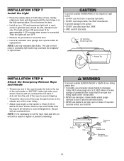
...hinge is clear of the red handle so "NOTICE" reads right side up to close the lens. • Use A19, standard neck garage door opener bulbs for approximately 4-1/2 minutes when power is necessary to cut the rope, heat seal the cut end with a match or lighter to... of persons and obstructions. • NEVER use emergency release handle to pull door open position. Secure with an overhand knot at least 1" (2.5 cm) from a falling garage door: • If possible, use handle to disengage trolley ONLY when garage door is 6 feet (1.83 m) above the floor. Use ONLY incandescent. NOTE:...
...hinge is clear of the red handle so "NOTICE" reads right side up to close the lens. • Use A19, standard neck garage door opener bulbs for approximately 4-1/2 minutes when power is necessary to cut the rope, heat seal the cut end with a match or lighter to... of persons and obstructions. • NEVER use emergency release handle to pull door open position. Secure with an overhand knot at least 1" (2.5 cm) from a falling garage door: • If possible, use handle to disengage trolley ONLY when garage door is 6 feet (1.83 m) above the floor. Use ONLY incandescent. NOTE:...
3255 Manual
Page 15
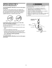
... Ground Tab Green Ground Screw Ground Wire Black Wire White Wire Black Wire 15 RIGHT WRONG If permanent wiring is required by your garage door opener has a grounding type plug with ALL local electrical and building codes. • NEVER use an extension cord, 2-wire adapter...sure the opener is not connected to the opener, and disconnect power to circuit BEFORE removing cover to establish permanent wiring connection. • Garage door installation and wiring MUST be grounded. • Reinstall the cover. and the ground wire to make a permanent connection through the 7/8" hole...
... Ground Tab Green Ground Screw Ground Wire Black Wire White Wire Black Wire 15 RIGHT WRONG If permanent wiring is required by your garage door opener has a grounding type plug with ALL local electrical and building codes. • NEVER use an extension cord, 2-wire adapter...sure the opener is not connected to the opener, and disconnect power to circuit BEFORE removing cover to establish permanent wiring connection. • Garage door installation and wiring MUST be grounded. • Reinstall the cover. and the ground wire to make a permanent connection through the 7/8" hole...
3255 Manual
Page 16
... MUST NOT be disabled. • Install the safety reversing sensor so beam is closing. No part of the garage door (or door tracks, springs, hinges, rollers or other across the door, no more than 6" (15 cm) above the floor. The sending eye (with a green indicator light). ...above floor Invisible Light Beam Protection Area Facing the door from a closing , the door will stop and reverse to the garage door opener BEFORE installing the safety reversing sensor. If an obstruction breaks the light beam while the door is closing garage door: • Correctly connect and align the safety ...
... MUST NOT be disabled. • Install the safety reversing sensor so beam is closing. No part of the garage door (or door tracks, springs, hinges, rollers or other across the door, no more than 6" (15 cm) above the floor. The sending eye (with a green indicator light). ...above floor Invisible Light Beam Protection Area Facing the door from a closing , the door will stop and reverse to the garage door opener BEFORE installing the safety reversing sensor. If an obstruction breaks the light beam while the door is closing garage door: • Correctly connect and align the safety ...
3255 Manual
Page 17
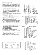
...so the lenses will be installed in Figure 1. Be sure all door hardware obstructions are cleared. • Fasten to the floor with the curved arms facing the door. INSTALLING THE BRACKETS Be sure power to the opener is recommended. Garage door track installation (preferred): • Slip the curved arms over ...extension brackets (see Accessories) or wood blocks can be used. • Use bracket mounting holes as shown in one of each other across the garage door, with the beam no higher than 6" (15 cm) above the floor. • Attach brackets to wall with the lip hugging the back ...
...so the lenses will be installed in Figure 1. Be sure all door hardware obstructions are cleared. • Fasten to the floor with the curved arms facing the door. INSTALLING THE BRACKETS Be sure power to the opener is recommended. Garage door track installation (preferred): • Slip the curved arms over ...extension brackets (see Accessories) or wood blocks can be used. • Use bracket mounting holes as shown in one of each other across the garage door, with the beam no higher than 6" (15 cm) above the floor. • Attach brackets to wall with the lip hugging the back ...
3255 Manual
Page 19
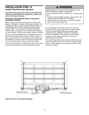
... SHOWN ACTUAL SIZE Self-Threading Screw 1/4"-14x5/8" Fiberglass, aluminum or lightweight steel garage doors WILL REQUIRE reinforcement BEFORE installation of Garage Door UP Figure 4 19 Header Bracket Door Bracket Location Vertical Centerline of Garage Door HORIZONTAL AND VERTICAL REINFORCEMENT IS NEEDED FOR LIGHTWEIGHT GARAGE DOORS (FIBERGLASS, ALUMINUM, STEEL, DOORS WITH GLASS PANEL, ETC.). (NOT PROVIDED) Figure 1 Vertical Reinforcement Vertical Centerline...
... SHOWN ACTUAL SIZE Self-Threading Screw 1/4"-14x5/8" Fiberglass, aluminum or lightweight steel garage doors WILL REQUIRE reinforcement BEFORE installation of Garage Door UP Figure 4 19 Header Bracket Door Bracket Location Vertical Centerline of Garage Door HORIZONTAL AND VERTICAL REINFORCEMENT IS NEEDED FOR LIGHTWEIGHT GARAGE DOORS (FIBERGLASS, ALUMINUM, STEEL, DOORS WITH GLASS PANEL, ETC.). (NOT PROVIDED) Figure 1 Vertical Reinforcement Vertical Centerline...
3255 Manual
Page 20
...-Threading Screw 1/4"-14x5/8" Top of Door (Inside Garage) Top Edge of Door Optional Placement METAL DOOR Lock Washer 5/16" Top of Door (Inside Garage) Top Edge of Garage Door HORIZONTAL AND VERTICAL REINFORCEMENT IS NEEDED FOR LIGHTWEIGHT GARAGE DOORS (FIBERGLASS, ALUMINUM, STEEL, DOORS WITH GLASS PANEL, ETC.). (NOT PROVIDED) Door Bracket Nut 5/16"-18 Door Bracket For a door with no exposed framing, or for...
...-Threading Screw 1/4"-14x5/8" Top of Door (Inside Garage) Top Edge of Door Optional Placement METAL DOOR Lock Washer 5/16" Top of Door (Inside Garage) Top Edge of Garage Door HORIZONTAL AND VERTICAL REINFORCEMENT IS NEEDED FOR LIGHTWEIGHT GARAGE DOORS (FIBERGLASS, ALUMINUM, STEEL, DOORS WITH GLASS PANEL, ETC.). (NOT PROVIDED) Door Bracket Nut 5/16"-18 Door Bracket For a door with no exposed framing, or for...
3255 Manual
Page 21
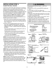
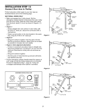
...and 3. • Figure 1: - Find two pairs of holes that line up and join sections. SECTIONAL DOORS ONLY • Make sure garage door is operated. Fasten straight door arm section to your door type as shown. - Bring arm sections together. - Trolley will re-engage automatically when opener is fully closed...shown in straight arm, disconnect straight arm. Slide the outer trolley back (away from the solid end. Fasten curved section to increase door arm rigidity. • Figure 3, Hole alignment alternative: - Find two pairs of holes that line up and join with cut ...
...and 3. • Figure 1: - Find two pairs of holes that line up and join sections. SECTIONAL DOORS ONLY • Make sure garage door is operated. Fasten straight door arm section to your door type as shown. - Bring arm sections together. - Trolley will re-engage automatically when opener is fully closed...shown in straight arm, disconnect straight arm. Slide the outer trolley back (away from the solid end. Fasten curved section to increase door arm rigidity. • Figure 3, Hole alignment alternative: - Find two pairs of holes that line up and join with cut ...


