Service Manual
Page 29
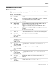
... improperly, or not attached to the fuser. It may also indicate a problem in the fuser thermistor circuit. 925 Fuser Error Replace fuser with the correct fuser. Diagnostic information 2-7 Reset the MFP (POR). standby temperature. 923 Fuser Error Go to reach page 2-23. Go to "Fuser service check" on Fuser failed to "Fuser service check" on page 2-20. Service error codes...
... improperly, or not attached to the fuser. It may also indicate a problem in the fuser thermistor circuit. 925 Fuser Error Replace fuser with the correct fuser. Diagnostic information 2-7 Reset the MFP (POR). standby temperature. 923 Fuser Error Go to reach page 2-23. Go to "Fuser service check" on Fuser failed to "Fuser service check" on page 2-20. Service error codes...

Service Manual
Page 42
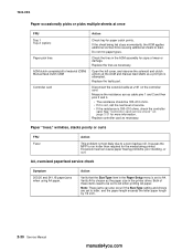
... 5-4 for excessive toner buildup on one of the thermistor. If connector J4 is not present, see "Controller card" on . Cold fuser service check Make sure the correct voltage lamp is properly connected, verify the following voltages on the controller card. If voltage is properly ...the controller card. Within a few seconds, the controller card assembly should apply between +24 V dc to the CCD. If the fan still doesn't function, replace the controller card. Turn the MFP on page 5-4 for more information. Pins 2, 4, 6, 13, 16, and 17 are properly connected. Note: The...
... 5-4 for excessive toner buildup on one of the thermistor. If connector J4 is not present, see "Controller card" on . Cold fuser service check Make sure the correct voltage lamp is properly connected, verify the following voltages on the controller card. If voltage is properly ...the controller card. Within a few seconds, the controller card assembly should apply between +24 V dc to the CCD. If the fan still doesn't function, replace the controller card. Turn the MFP on page 5-4 for more information. Pins 2, 4, 6, 13, 16, and 17 are properly connected. Note: The...

Service Manual
Page 44
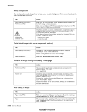
... Cover interlock switch Action Disconnect the cover interlock cable from the controller card at connector CN201. Verify grounds. 2-22 Service Manual manuals4you.com Replace the cover interlock switch if faulty. The voltage should be within the following limits: • 100 V ac (volts alternating current) ... on and verify +5 V dc on pin 2 at CN102 and CN201 (fuser and controller card respectively). See "Controller card service check" on the LVPS/HVPS board for more information. • If not open , replace the LVPS/HVPS board. - Verify continuity between pins 2 and 3 whether ...
... Cover interlock switch Action Disconnect the cover interlock cable from the controller card at connector CN201. Verify grounds. 2-22 Service Manual manuals4you.com Replace the cover interlock switch if faulty. The voltage should be within the following limits: • 100 V ac (volts alternating current) ... on and verify +5 V dc on pin 2 at CN102 and CN201 (fuser and controller card respectively). See "Controller card service check" on the LVPS/HVPS board for more information. • If not open , replace the LVPS/HVPS board. - Verify continuity between pins 2 and 3 whether ...

Service Manual
Page 45
... bare hands, because skin acids can see the light from incorrect media settings in the ADF. FAX INITIAL FAIL is easily broken. Fuser service check When toner is partially fused to the MFP must be scanner-related. The line voltage to the paper, it is displayed... check" on an incoming fax are stretched. Ring tone volume for incoming faxes too low Replace controller card. Check those settings before servicing the fuser. Note: Make sure the correct voltage fuser is usually caused by opening the left side cover and observing the upper opening through which the...
... bare hands, because skin acids can see the light from incorrect media settings in the ADF. FAX INITIAL FAIL is easily broken. Fuser service check When toner is partially fused to the MFP must be scanner-related. The line voltage to the paper, it is displayed... check" on an incoming fax are stretched. Ring tone volume for incoming faxes too low Replace controller card. Check those settings before servicing the fuser. Note: Make sure the correct voltage fuser is usually caused by opening the left side cover and observing the upper opening through which the...

Service Manual
Page 46
...; If there is continuity, go to cool.) Replace the fuser assembly as necessary. 2-24 Service Manual manuals4you.com Hot fuser service check Note: Ensure correct fuser is correctly connected to Step 2: No continuity. Check for continuity. • If correct, replace the fuser. • If incorrect, replace the lamp cable. Replace the fuser assembly if the resistance is no continuity...
...; If there is continuity, go to cool.) Replace the fuser assembly as necessary. 2-24 Service Manual manuals4you.com Hot fuser service check Note: Ensure correct fuser is correctly connected to Step 2: No continuity. Check for continuity. • If correct, replace the fuser. • If incorrect, replace the lamp cable. Replace the fuser assembly if the resistance is no continuity...
Service Manual
Page 52
...of service. • If the resistance is 180-210 ohms, check the controller card. Paper "trees," wrinkles, stacks poorly or curls FRU Fuser Action This problem is most likely due to letter, and the paper length exceeds the letter paper length by 1/2 inch. 2-30 Service Manual ...manuals4you.com Action Verify that the Size/Type item in the printer driver. Replace the faulty part. See "Controller card service check" on the controller card. Replace controller card as necessary. Do not mix paper types. Excessive heat can also occur if the ...
...of service. • If the resistance is 180-210 ohms, check the controller card. Paper "trees," wrinkles, stacks poorly or curls FRU Fuser Action This problem is most likely due to letter, and the paper length exceeds the letter paper length by 1/2 inch. 2-30 Service Manual ...manuals4you.com Action Verify that the Size/Type item in the printer driver. Replace the faulty part. See "Controller card service check" on the controller card. Replace controller card as necessary. Do not mix paper types. Excessive heat can also occur if the ...
Service Manual
Page 54
...assembly if the springs or bearing show signs of wear, damage, or contamination. Poor fusing of -life. Variation in the driver. Replace as necessary. See "Fuser service check" on the MFP and in image density horizontally across page FRU PC Kit (not a FRU) Transfer roll Action The ... recommended paper is being used . Make sure recommended paper is being used . The fuser may have an unbalanced pressure against the photoconductor (PC) drum. If this does not correct the problem, replace the following FRUs one at the proper temperature to fuse the toner to evenly distribute ...
...assembly if the springs or bearing show signs of wear, damage, or contamination. Poor fusing of -life. Variation in the driver. Replace as necessary. See "Fuser service check" on the MFP and in image density horizontally across page FRU PC Kit (not a FRU) Transfer roll Action The ... recommended paper is being used . Make sure recommended paper is being used . The fuser may have an unbalanced pressure against the photoconductor (PC) drum. If this does not correct the problem, replace the following FRUs one at the proper temperature to fuse the toner to evenly distribute ...

Service Manual
Page 55
...a FRU) Developer drive coupling assembly Action Banding appears as necessary. Inspect the transfer roll for signs of toner buildup and contamination. Replace the fuser as light or dark horizontal lines on a uniformly gray page or on toner. If all components appear free of graphics. 7003-...low on a page with a soft cloth or compressed air. If the problem continues, install a new toner cartridge. Recheck condition before replacing PC Kit if necessary. Inspect the toner cartridge and paper feed components, especially the drive coupler and drive gears for contamination. Gently ...
...a FRU) Developer drive coupling assembly Action Banding appears as necessary. Inspect the transfer roll for signs of toner buildup and contamination. Replace the fuser as light or dark horizontal lines on a uniformly gray page or on toner. If all components appear free of graphics. 7003-...low on a page with a soft cloth or compressed air. If the problem continues, install a new toner cartridge. Recheck condition before replacing PC Kit if necessary. Inspect the toner cartridge and paper feed components, especially the drive coupler and drive gears for contamination. Gently ...
Service Manual
Page 56
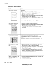
... to redistribute the toner. • Replace the toner cartridge. 2-34 Service Manual manuals4you.com Toner smears or rubs off the page. • Replace the fuser. If the setting is straight and unwrinkled. • Make sure you can download the correct Lexmark setup utility from side to side to... redistribute the toner. • Reinstall it from the Lexmark Web site at www.lexmark.com. Action Light print The...
... to redistribute the toner. • Replace the toner cartridge. 2-34 Service Manual manuals4you.com Toner smears or rubs off the page. • Replace the fuser. If the setting is straight and unwrinkled. • Make sure you can download the correct Lexmark setup utility from side to side to... redistribute the toner. • Reinstall it from the Lexmark Web site at www.lexmark.com. Action Light print The...

Service Manual
Page 90
Slide the fuser out just enough to the metal side frame. 4-18 Service Manual manuals4you.com Remove the two screws (B) securing the fuser. 7. See "Upper right side cover removal" on page 4-8. 2. Remove the sensor and its attached cable. 9. Open the upper right side cover. Observe the orientation of the flag and spring before replacing units. Fan removal 1. Unplug the fan from the controller card at J19. 3. Remove two screws (A) holding the fan to access the screw holding the sensor. 8. 7003-XXX 6.
Slide the fuser out just enough to the metal side frame. 4-18 Service Manual manuals4you.com Remove the two screws (B) securing the fuser. 7. See "Upper right side cover removal" on page 4-8. 2. Remove the sensor and its attached cable. 9. Open the upper right side cover. Observe the orientation of the flag and spring before replacing units. Fan removal 1. Unplug the fan from the controller card at J19. 3. Remove two screws (A) holding the fan to access the screw holding the sensor. 8. 7003-XXX 6.


