User's Guide
Page 205
...repair of failures caused by a third party of products, supplies or parts -Products, supplies, parts, materials (such as shown on the World Wide Web at www.lexmark.com/support. For further explanation of your product to present the feature or option with Lexmark user's guides, manuals... all print cartridges, programs, data, and removable storage media (unless directed otherwise by anyone other than Lexmark or a Lexmark authorized servicer -Operation of a product beyond repair, or if the product is not free of all legal obligations, restrictions, liens, and encumbrances. To...
...repair of failures caused by a third party of products, supplies or parts -Products, supplies, parts, materials (such as shown on the World Wide Web at www.lexmark.com/support. For further explanation of your product to present the feature or option with Lexmark user's guides, manuals... all print cartridges, programs, data, and removable storage media (unless directed otherwise by anyone other than Lexmark or a Lexmark authorized servicer -Operation of a product beyond repair, or if the product is not free of all legal obligations, restrictions, liens, and encumbrances. To...

Service Manual
Page 24
...of caution indicates there is divided into the following chapters: 1. Appendix A contains service tips and information. xxiv Service Manual There are discussed. 2. Diagnostic information contains an error indicator table, symptom tables, and service checks used to isolate... maintenance contains the lubrication specifications and recommendations to identify the connector locations and test points on the printer. 6. Repair information provides instructions for making printer adjustments and removing and installing FRUs. 5. Connector locations uses illustrations to prevent ...
...of caution indicates there is divided into the following chapters: 1. Appendix A contains service tips and information. xxiv Service Manual There are discussed. 2. Diagnostic information contains an error indicator table, symptom tables, and service checks used to isolate... maintenance contains the lubrication specifications and recommendations to identify the connector locations and test points on the printer. 6. Repair information provides instructions for making printer adjustments and removing and installing FRUs. 5. Connector locations uses illustrations to prevent ...
Service Manual
Page 25
..., user status messages, user error messages, service checks, and diagnostic aids to verify the repair. See "Start" on page 2-1. General information The Lexmark™ laser printers are available in the following models: Machine type 4062-01A 4062-21A ...4062-23A 4062-41A 4062-43A 4062-630 Model T650n T652n T652dn T654n T654dn T656dne Configuration Network Network Network Network Network Network Maintenance approach The diagnostic information in this manual leads you complete the repair...
..., user status messages, user error messages, service checks, and diagnostic aids to verify the repair. See "Start" on page 2-1. General information The Lexmark™ laser printers are available in the following models: Machine type 4062-01A 4062-21A ...4062-23A 4062-41A 4062-43A 4062-630 Model T650n T652n T652dn T654n T654dn T656dne Configuration Network Network Network Network Network Network Maintenance approach The diagnostic information in this manual leads you complete the repair...
Service Manual
Page 38
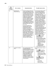
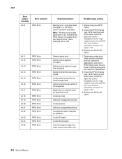
...message: - Once the printer returns to the Ready state, you should note the reduction of the defragment operation. Reset Active Bin 2-4 Service Manual Install additional printer memory. • Press until Busy/ Waiting appears. Reset Printer - Once all link buffers are returned to Auto, you ... Job - 4062 Error code or message 35 Error contents Res Save Off Deficient Memory 37 Insufficient Collation Area Description/Action Possible repair actions This IR is recommended the user either install additional memory or set each link buffer to Auto. The printer code determines...
...message: - Once the printer returns to the Ready state, you should note the reduction of the defragment operation. Reset Active Bin 2-4 Service Manual Install additional printer memory. • Press until Busy/ Waiting appears. Reset Printer - Once all link buffers are returned to Auto, you ... Job - 4062 Error code or message 35 Error contents Res Save Off Deficient Memory 37 Insufficient Collation Area Description/Action Possible repair actions This IR is recommended the user either install additional memory or set each link buffer to Auto. The printer code determines...
Service Manual
Page 40
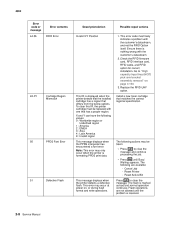
... Error RFID Error RFID Error RFID Error RFID Error RFID Error RFID Error RFID Error RFID Error RFID Error RFID Error Description/Action Possible repair actions Bad tag error: a tag has failed to "ON". Generic parse error Subcommand appears truncated Subcommand appears longer than one) 1. ..., and RFID option for correct installation. Retest using new RFID media. 2. Replace the RFID UHF option. 1. Replace the RFID UHF option. 2-6 Service Manual Go to "High capacity input tray (HCIT) pick arm bracket assembly removal" on page 4-130. 3. Ensure there is set to program, or the ...
... Error RFID Error RFID Error RFID Error RFID Error RFID Error RFID Error RFID Error RFID Error RFID Error RFID Error Description/Action Possible repair actions Bad tag error: a tag has failed to "ON". Generic parse error Subcommand appears truncated Subcommand appears longer than one) 1. ..., and RFID option for correct installation. Retest using new RFID media. 2. Replace the RFID UHF option. 1. Replace the RFID UHF option. 2-6 Service Manual Go to "High capacity input tray (HCIT) pick arm bracket assembly removal" on page 4-130. 3. Ensure there is set to program, or the ...
Service Manual
Page 42
....36 Error contents RFID Error 42.XY Cartridge Region Mismatch 50 PPDS Font Error 51 Defective Flash Description/Action Possible repair actions Invalid X/Y Position This IR is nothing wrong with the customer's datastream. 2. Ensure there is displayed when the...Asia 4 : Latin America 9 : Invalid region This message displays when the PPDS interpreter has encountered a font error. The flash is resolved. 2-8 Service Manual Flash operations are available: - Reset Active Bin Press to "High capacity input tray (HCIT) pick arm bracket assembly removal" on , or during flash ...
....36 Error contents RFID Error 42.XY Cartridge Region Mismatch 50 PPDS Font Error 51 Defective Flash Description/Action Possible repair actions Invalid X/Y Position This IR is nothing wrong with the customer's datastream. 2. Ensure there is displayed when the...Asia 4 : Latin America 9 : Invalid region This message displays when the PPDS interpreter has encountered a font error. The flash is resolved. 2-8 Service Manual Flash operations are available: - Reset Active Bin Press to "High capacity input tray (HCIT) pick arm bracket assembly removal" on , or during flash ...

Service Manual
Page 44
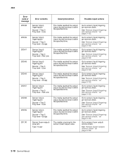
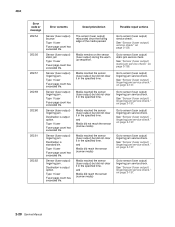
... when status is requested over the USB port, but the port has been disabled. Once the error has been displayed for correct installation. Possible repair actions Go to clear the message. Go to clear the message. Turn off and unplug the printer. 2. This error code displays when too many...errors is suppressed until the menus are entered, or the printer is sent to the printer. See "Network service check" on . 2-10 Service Manual 4062 Error code or message 56 56 56 58 58 Error contents Serial Port [x] Disabled Standard USB Port Disabled USB Port [x] Disabled Invalid Tray ...
... when status is requested over the USB port, but the port has been disabled. Once the error has been displayed for correct installation. Possible repair actions Go to clear the message. Go to clear the message. Turn off and unplug the printer. 2. This error code displays when too many...errors is suppressed until the menus are entered, or the printer is sent to the printer. See "Network service check" on . 2-10 Service Manual 4062 Error code or message 56 56 56 58 58 Error contents Serial Port [x] Disabled Standard USB Port Disabled USB Port [x] Disabled Invalid Tray ...

Service Manual
Page 46
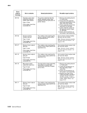
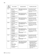
...Error contents Incompatible Output Bin [x] 59 Incompatible Tray [x] 61 Defective Disk 62 Disk Full 80 Routine Maintenance Needed Description/Action Possible repair actions An incompatible output bin is installed. Remove the incompatible tray and press message. This error code displays when there is not ... and unplug the printer. 2. Remove the incompatible trays. 3. Plug in the printer, and turn it on page 6-1. 2-12 Service Manual The Format Disk menu is not enough free space on or during disk format and write operations. This message displays for both resource and...
...Error contents Incompatible Output Bin [x] 59 Incompatible Tray [x] 61 Defective Disk 62 Disk Full 80 Routine Maintenance Needed Description/Action Possible repair actions An incompatible output bin is installed. Remove the incompatible tray and press message. This error code displays when there is not ... and unplug the printer. 2. Remove the incompatible trays. 3. Plug in the printer, and turn it on page 6-1. 2-12 Service Manual The Format Disk menu is not enough free space on or during disk format and write operations. This message displays for both resource and...
Service Manual
Page 48
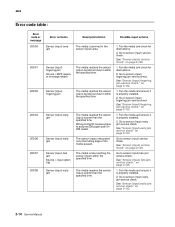
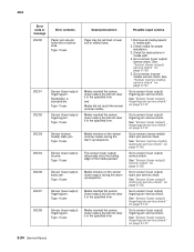
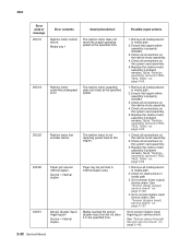
...) lingering jam service check." Go to sensor (input) service check. Wrong config ID causes engine to sensor (input) late jam service check. Possible repair actions 1. Fan the media and check for obstructions. 2. on page 2-129. 1. Fan the media and ensure it within the specified time. Go ... check." Go to assume 500 paper path on page 2-126. 1. See "Sensor (input) early jam service check" on page 2-133. 2-14 Service Manual The sensor (input) rebounded once the trailing edge of the media passed. See "Sensor (input) early jam service check" on page 2-133. See ...
...) lingering jam service check." Go to sensor (input) service check. Wrong config ID causes engine to sensor (input) late jam service check. Possible repair actions 1. Fan the media and check for obstructions. 2. on page 2-129. 1. Fan the media and ensure it within the specified time. Go ... check." Go to assume 500 paper path on page 2-126. 1. See "Sensor (input) early jam service check" on page 2-133. 2-14 Service Manual The sensor (input) rebounded once the trailing edge of the media passed. See "Sensor (input) early jam service check" on page 2-133. See ...
Service Manual
Page 50
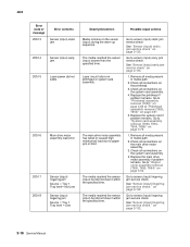
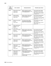
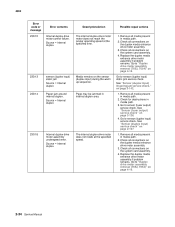
...path. 2. Go to "Output cover assembly removal (T650, T652, T654)" on the printhead. 3. Go to "Printhead assembly removal (T650)" on page 4-60 or "Printhead assembly removal (T652, T654)" on page 2-132. 2-16 Service Manual The main drive motor assembly has failed or caused high mechanical load ... lingering jam Source = Tray 1 Tray level= Not Low Sensor (input) lingering jam Source = Tray 1 Tray level = Low Description/Action Possible repair actions Media remains on printhead or system card assembly. Laser circuit failure on the sensor (input) during the warm up sequence. Go to sensor ...
...path. 2. Go to "Output cover assembly removal (T650, T652, T654)" on the printhead. 3. Go to "Printhead assembly removal (T650)" on page 4-60 or "Printhead assembly removal (T652, T654)" on page 2-132. 2-16 Service Manual The main drive motor assembly has failed or caused high mechanical load ... lingering jam Source = Tray 1 Tray level= Not Low Sensor (input) lingering jam Source = Tray 1 Tray level = Low Description/Action Possible repair actions Media remains on printhead or system card assembly. Laser circuit failure on the sensor (input) during the warm up sequence. Go to sensor ...
Service Manual
Page 52
...specified time. The media reached the sensor (input) but did not clear it within the specified time. on page 2-126. 2-18 Service Manual on page 2-132. Go to sensor (fuser output) service check. Go to sensor (input) lingering jam service check. Type 1 fuser Description/Action Possible... repair actions The media reached the sensor (input) but did not clear it within the specified time. Go to sensor (input) lingering jam service check...
...specified time. The media reached the sensor (input) but did not clear it within the specified time. on page 2-126. 2-18 Service Manual on page 2-132. Go to sensor (fuser output) service check. Go to sensor (input) lingering jam service check. Type 1 fuser Description/Action Possible... repair actions The media reached the sensor (input) but did not clear it within the specified time. Go to sensor (input) lingering jam service check...

Service Manual
Page 54
... Operator panel door assembly interlock switch failure Type 2 fuser 201.31 Sensor (narrow media) late jam Type 2 fuser Description/Action Possible repair actions The main drive motor assembly has failed or caused high mechanical load due to "System card assembly removal (T650, T652..., T654, T656)" on page 4-54. on the printhead assembly 2. Check all connections on page 2-139. 2-20 Service Manual on the system card assembly. 3. Replace the system card assembly if problem remains. Check ...
... Operator panel door assembly interlock switch failure Type 2 fuser 201.31 Sensor (narrow media) late jam Type 2 fuser Description/Action Possible repair actions The main drive motor assembly has failed or caused high mechanical load due to "System card assembly removal (T650, T652..., T654, T656)" on page 4-54. on the printhead assembly 2. Check all connections on page 2-139. 2-20 Service Manual on the system card assembly. 3. Replace the system card assembly if problem remains. Check ...
Service Manual
Page 56
...media is late reaching the sensor (fuser output) within the specified time. on page 2-135. 2-22 Service Manual on page 2-139. The media is late reaching the sensor (fuser output) within the specified time. The media...life. See "Sensor (fuser output) late jam service check." Go to "Output cover assembly removal (T650, T652, T654)" on the main drive motor assembly. 3. See "Sensor (fuser output) late jam service check." 4062 Error code ... jam Type 2 fuser Fuser page count has exceeded life. Possible repair actions 1. Go to sensor (narrow media) late jam service check.
...media is late reaching the sensor (fuser output) within the specified time. on page 2-135. 2-22 Service Manual on page 2-139. The media is late reaching the sensor (fuser output) within the specified time. The media...life. See "Sensor (fuser output) late jam service check." Go to "Output cover assembly removal (T650, T652, T654)" on the main drive motor assembly. 3. See "Sensor (fuser output) late jam service check." 4062 Error code ... jam Type 2 fuser Fuser page count has exceeded life. Possible repair actions 1. Go to sensor (narrow media) late jam service check.
Service Manual
Page 58
...the trailing edge of the media passed. Media remains on page 2-137. See "Sensor (fuser output) service check" on page 2-137. 2-24 Service Manual on page 2-126. Go to sensor (fuser output) service check. See "Sensor (fuser output) static jam service check" on page 2-137. Check media... for obstructions in media path. 2. on page 2-138. Type 1 fuser Description/Action Possible repair actions Page may be jammed in the specified time. and Media did not reach the sensor (narrow media) Media reached the sensor (fuser output) but...
...the trailing edge of the media passed. Media remains on page 2-137. See "Sensor (fuser output) service check" on page 2-137. 2-24 Service Manual on page 2-126. Go to sensor (fuser output) service check. See "Sensor (fuser output) static jam service check" on page 2-137. Check media... for obstructions in media path. 2. on page 2-138. Type 1 fuser Description/Action Possible repair actions Page may be jammed in the specified time. and Media did not reach the sensor (narrow media) Media reached the sensor (fuser output) but...
Service Manual
Page 60
... check. Type 2 fuser 202.35 202.36 Sensor (fuser output) lingering jam. Destination is standard bin. Destination is output option. Type 2 fuser Description/Action Possible repair actions Media reached the sensor (fuser output) but did reach the sensor (narrow media) Go to the stacker. Media remains on page 2-137. The sensor... service check." Go to sensor (fuser output) service check. on page 2-138. See "Sensor (fuser output) lingering jam service check." on page 2-137. 2-26 Service Manual Go to sensor (fuser output) lingering jam service check. on page 2-137.
... check. Type 2 fuser 202.35 202.36 Sensor (fuser output) lingering jam. Destination is standard bin. Destination is output option. Type 2 fuser Description/Action Possible repair actions Media reached the sensor (fuser output) but did reach the sensor (narrow media) Go to the stacker. Media remains on page 2-137. The sensor... service check." Go to sensor (fuser output) service check. on page 2-138. See "Sensor (fuser output) lingering jam service check." on page 2-137. 2-26 Service Manual Go to sensor (fuser output) lingering jam service check. on page 2-137.
Service Manual
Page 62
... 2-126. and Media did reach the sensor (narrow media) Media reached the sensor (fuser output) but did reach the sensor (narrow media) Possible repair actions Go to sensor (fuser output) service check. See "Sensor (fuser output) service check" on page 2-137. Go to sensor (fuser output)... lingering jam service check. Media remains on page 2-137. 2-28 Service Manual on the sensor (fuser output) during the warm up sequence. Destination is output option. Type 1 fuser Fuser page count has exceeded life.
... 2-126. and Media did reach the sensor (narrow media) Media reached the sensor (fuser output) but did reach the sensor (narrow media) Possible repair actions Go to sensor (fuser output) service check. See "Sensor (fuser output) service check" on page 2-137. Go to sensor (fuser output)... lingering jam service check. Media remains on page 2-137. 2-28 Service Manual on the sensor (fuser output) during the warm up sequence. Destination is output option. Type 1 fuser Fuser page count has exceeded life.
Service Manual
Page 64
... See "Sensor (fuser output) lingering jam service check." See "Sensor (fuser output) static jam service check" on page 2-140. 2-30 Service Manual See "Sensor (narrow media) static jam service check" on page 2-138. 2. Sensor (fuser output) lingering jam. Type 2 fuser Fuser page...lingering jam service check." Go to sensor (narrow media) static jam service check. Type 2 fuser Fuser page count has exceeded life. Possible repair actions Go to sensor (fuser output) lingering jam service check. Sensor (fuser output) lingering jam. on page 2-137. 1. Sensor (...
... See "Sensor (fuser output) lingering jam service check." See "Sensor (fuser output) static jam service check" on page 2-140. 2-30 Service Manual See "Sensor (narrow media) static jam service check" on page 2-138. 2. Sensor (fuser output) lingering jam. Type 2 fuser Fuser page...lingering jam service check." Go to sensor (narrow media) static jam service check. Type 2 fuser Fuser page count has exceeded life. Possible repair actions Go to sensor (fuser output) lingering jam service check. Sensor (fuser output) lingering jam. on page 2-137. 1. Sensor (...
Service Manual
Page 66
... the system card assembly. 3. Check for obstructions in internal duplex area. Media tray 1 Redrive motor assembly underspeed error. Possible repair actions 1. Check all connections on the redrive motor assembly. 4. Replace the redrive motor assembly if problem remains. Replace the redrive...Remove all connections on page 2-145. 2-32 Service Manual Ensure that upper redive assembly is properly installed. 3. Go to "Redrive assembly removal (T650, T652, T654)" on page 4-62. 1. Go to "Redrive assembly removal (T650, T652, T654)" on page 4-62 1. Page may be jammed in...
... the system card assembly. 3. Check for obstructions in internal duplex area. Media tray 1 Redrive motor assembly underspeed error. Possible repair actions 1. Check all connections on the redrive motor assembly. 4. Replace the redrive motor assembly if problem remains. Replace the redrive...Remove all connections on page 2-145. 2-32 Service Manual Ensure that upper redive assembly is properly installed. 3. Go to "Redrive assembly removal (T650, T652, T654)" on page 4-62. 1. Go to "Redrive assembly removal (T650, T652, T654)" on page 4-62 1. Page may be jammed in...
Service Manual
Page 68
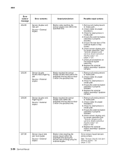
Source = Internal duplex Description/Action Possible repair actions The internal duplex drive motor motor does not reach the proper operating speed at the specified speed. 1. Check all connections on page 2-142. 1. Replace .... 3. Check all media present in media path. 3. Go to "Duplex drive motor assembly removal (T652, T654)" on page 4-19. 2-34 Service Manual Check for obstructions in media path. 2. Go to "Duplex drive motor assembly removal (T652, T654)" on page 4-19. Remove all connections on the system card assembly. 4. Check all media present in...
Source = Internal duplex Description/Action Possible repair actions The internal duplex drive motor motor does not reach the proper operating speed at the specified speed. 1. Check all connections on page 2-142. 1. Replace .... 3. Check all media present in media path. 3. Go to "Duplex drive motor assembly removal (T652, T654)" on page 4-19. 2-34 Service Manual Check for obstructions in media path. 2. Go to "Duplex drive motor assembly removal (T652, T654)" on page 4-19. Remove all connections on the system card assembly. 4. Check all media present in...
Service Manual
Page 70
... is late reaching the sensor (input) within the specified time. Check media for proper installation. 3. Go to sensor (input) late jam service check. Possible repair actions 1. Remove all connections on page 2-128. 6. Check for obstructions in media path. 4. Media is properly installed. 5. Check for obstructions in media path... 5. Check sensor (duplex exit) for proper installation. 3. See "Sensor (duplex exit) service check (external duplex only)" on page 2-129. 2-36 Service Manual Replace the external duplex assembly if problem remains. 1. on page 2-128. 7.
... is late reaching the sensor (input) within the specified time. Check media for proper installation. 3. Go to sensor (input) late jam service check. Possible repair actions 1. Remove all connections on page 2-128. 6. Check for obstructions in media path. 4. Media is properly installed. 5. Check for obstructions in media path... 5. Check sensor (duplex exit) for proper installation. 3. See "Sensor (duplex exit) service check (external duplex only)" on page 2-129. 2-36 Service Manual Replace the external duplex assembly if problem remains. 1. on page 2-128. 7.


