User's Guide
Page 98
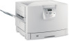
Photodeveloper Warning: Never touch the photodeveloper drum on how to open the top cover, see Open the top cover. Note: The paper may be covered with unfused toner, which can stain garments. 200 Paper Jam Pages Jammed (Check Areas A-F, T1-5, MPF) 98 To clear area A: 1 Complete the steps to open the top cover. Note: If you need instructions on the underside of the toner cartridge. Clearing jams Check Area A This message indicates a paper jam in the transfer belt area.
Photodeveloper Warning: Never touch the photodeveloper drum on how to open the top cover, see Open the top cover. Note: The paper may be covered with unfused toner, which can stain garments. 200 Paper Jam Pages Jammed (Check Areas A-F, T1-5, MPF) 98 To clear area A: 1 Complete the steps to open the top cover. Note: If you need instructions on the underside of the toner cartridge. Clearing jams Check Area A This message indicates a paper jam in the transfer belt area.
User's Guide
Page 100
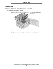
To clear area B: 1 Complete the steps to open the top cover. The paper may be covered with unfused toner, which can stain garments. 200 Paper Jam Pages Jammed (Check Areas A-F, T1-5, MPF) 100 Clearing jams Check Area B This message indicates a paper jam in the fuser or output roller area. Photodeveloper Warning: Never touch the photodeveloper drum on how to open the top cover, see Open the top cover. Note: If you need instructions on the underside of the toner cartridge.
To clear area B: 1 Complete the steps to open the top cover. The paper may be covered with unfused toner, which can stain garments. 200 Paper Jam Pages Jammed (Check Areas A-F, T1-5, MPF) 100 Clearing jams Check Area B This message indicates a paper jam in the fuser or output roller area. Photodeveloper Warning: Never touch the photodeveloper drum on how to open the top cover, see Open the top cover. Note: If you need instructions on the underside of the toner cartridge.
Service Manual
Page 4
... Motor Error 2-9 911 - RIP Fan Error 2-10 918 - Upper Fuser Thermistor Open Error 2-11 924 - Yellow Printhead Error 2-13 931 - Color Drum Sensor Error 2-15 935 - RAM Slot 1 Bad 2-20 961 - Unrecognizable Network Port 2-20 976 - Main Unit Fan Error 2-10 919 - Lower...10 917 - Toner Sensor Error 2-12 930 - Flash Parts Failed While Programming Network Port 2-21 980 Face Up/Down Switching Error 2-21 981 - Black Drum Sensor Error 2-15 936 - 939 Cassette Error 2-15 940 - Standard Network Error 2-20 975 - Tray (x) Comm 2-18 950 - High-Capacity Feed Tray...
... Motor Error 2-9 911 - RIP Fan Error 2-10 918 - Upper Fuser Thermistor Open Error 2-11 924 - Yellow Printhead Error 2-13 931 - Color Drum Sensor Error 2-15 935 - RAM Slot 1 Bad 2-20 961 - Unrecognizable Network Port 2-20 976 - Main Unit Fan Error 2-10 919 - Lower...10 917 - Toner Sensor Error 2-12 930 - Flash Parts Failed While Programming Network Port 2-21 980 Face Up/Down Switching Error 2-21 981 - Black Drum Sensor Error 2-15 936 - 939 Cassette Error 2-15 940 - Standard Network Error 2-20 975 - Tray (x) Comm 2-18 950 - High-Capacity Feed Tray...

Service Manual
Page 57
... frame assembly. Go to step 2 Replace the photo developer that called the error. Problem solved. Black Drum Sensor Error Step Questions/actions Yes No 1 Clean the black drum sensor LED. Did this fix the problem? 2 Swap the black photo developer with a different color photo... Did replacing the sub frame fix the problem? Replace the printer controller board. 935 - Color Drum Sensor Error 934 Service Drum Sensor Step Questions/actions Yes No 1 Clean the color drum sensor LED. Problem solved. Plug the connector in securely. Did this fix the problem? 3 ...
... frame assembly. Go to step 2 Replace the photo developer that called the error. Problem solved. Black Drum Sensor Error Step Questions/actions Yes No 1 Clean the black drum sensor LED. Did this fix the problem? 2 Swap the black photo developer with a different color photo... Did replacing the sub frame fix the problem? Replace the printer controller board. 935 - Color Drum Sensor Error 934 Service Drum Sensor Step Questions/actions Yes No 1 Clean the color drum sensor LED. Problem solved. Plug the connector in securely. Did this fix the problem? 3 ...

Service Manual
Page 63
... Programming Network Card Software error. 979 - Check to see if linkage from the FU/FD solenoid to step 3. Replace the printer controller board and the drum eraser assembly. Go to the network card option section. 978 - Can you hear the FU/FD solenoid move during the feed test? 2 Is there continuity...
... Programming Network Card Software error. 979 - Check to see if linkage from the FU/FD solenoid to step 3. Replace the printer controller board and the drum eraser assembly. Go to the network card option section. 978 - Can you hear the FU/FD solenoid move during the feed test? 2 Is there continuity...

Service Manual
Page 97
... roller (transfer roller) Photodeveloper charge roller Supply roller (toner cartridge) Upper registration roller Lower registration roller Developer roller (toner cartridge) OCR (oil coating roller) Photodeveloper drum Fuser upper roller Fuser lower roller Transfer belt Fuser part locations Thermistor hot roll Thermistor BUR TCO hot roll TCO BUR Detact fingers hot roll...
... roller (transfer roller) Photodeveloper charge roller Supply roller (toner cartridge) Upper registration roller Lower registration roller Developer roller (toner cartridge) OCR (oil coating roller) Photodeveloper drum Fuser upper roller Fuser lower roller Transfer belt Fuser part locations Thermistor hot roll Thermistor BUR TCO hot roll TCO BUR Detact fingers hot roll...

Service Manual
Page 103
... continuity. If the problem remains, replace the high voltage unit (HVU). If the fuse is present at the same time. Clean or replace the photodeveloper drum unit if necessary. Clean or replace the affected contacts or sub-frame. Power supply service check FRU 1 Voltage 2 Power cord 3 • Fuse • Switch •...
... continuity. If the problem remains, replace the high voltage unit (HVU). If the fuse is present at the same time. Clean or replace the photodeveloper drum unit if necessary. Clean or replace the affected contacts or sub-frame. Power supply service check FRU 1 Voltage 2 Power cord 3 • Fuse • Switch •...

Service Manual
Page 108
... No image Possible cause Moist paper LED printhead High voltage unit (HVU) Printer controller board Printhead controller board Black line Possible cause Photodeveloper drum • Fuser detach pawl • Fuser roller surface • Fuser thermistor surface LED printhead Action Be sure the printer is not ... LED printhead cable is noticeable between color fills, due to the printhead controller board and LED printhead assembly. Remove any dirt from the drum surface. Print a blank document. Be sure the charge roll or belt is On. A white gap is securely connected to poor color...
... No image Possible cause Moist paper LED printhead High voltage unit (HVU) Printer controller board Printhead controller board Black line Possible cause Photodeveloper drum • Fuser detach pawl • Fuser roller surface • Fuser thermistor surface LED printhead Action Be sure the printer is not ... LED printhead cable is noticeable between color fills, due to the printhead controller board and LED printhead assembly. Remove any dirt from the drum surface. Print a blank document. Be sure the charge roll or belt is On. A white gap is securely connected to poor color...

Service Manual
Page 109
... unit LED printhead unit LED printhead controller board High voltage unit (HVU) Transfer belt unit Action Be sure the toner cartridge and the PC drum unit are clean. If the problem remains, check the connector on the print unit are properly seated. If the problem remains, replace the ...high voltage unit. 5056-XXX Black print Possible cause High voltage unit (HVU) Sub-frame Photodeveloper drum set Action The printed paper has black print. If the problem remains after replacing the sub-frame, be sure the photodeveloper has clean contacts. ...
... unit LED printhead unit LED printhead controller board High voltage unit (HVU) Transfer belt unit Action Be sure the toner cartridge and the PC drum unit are clean. If the problem remains, check the connector on the print unit are properly seated. If the problem remains, replace the ...high voltage unit. 5056-XXX Black print Possible cause High voltage unit (HVU) Sub-frame Photodeveloper drum set Action The printed paper has black print. If the problem remains after replacing the sub-frame, be sure the photodeveloper has clean contacts. ...
Service Manual
Page 110
... support one 3.2 GB or larger hard disk option is clean and not damaged. 5056-XXX Periodic dirt Possible cause Oil coating fuser roller (OCR) Photoconductor drum Transfer belt unit Action Check for scratches or nicks. Serial port Run the "Serial Wrap Test" on the surface, and replace if necessary. If the...
... support one 3.2 GB or larger hard disk option is clean and not damaged. 5056-XXX Periodic dirt Possible cause Oil coating fuser roller (OCR) Photoconductor drum Transfer belt unit Action Check for scratches or nicks. Serial port Run the "Serial Wrap Test" on the surface, and replace if necessary. If the...

Service Manual
Page 116
5056-XXX Menu overview SUPPLIES MENU Cyan Toner Magenta Toner Yellow Toner Black Toner Cyan PC Drum Magenta PC Drum Yellow PC Drum Black PC Drum Oil Coating Roll Fuser Transfer Belt Staples Hole Punch Box PAPER MENU Default Source Paper Size / Type Configure MP Substitute Size Paper Weight Paper Loading ...
5056-XXX Menu overview SUPPLIES MENU Cyan Toner Magenta Toner Yellow Toner Black Toner Cyan PC Drum Magenta PC Drum Yellow PC Drum Black PC Drum Oil Coating Roll Fuser Transfer Belt Staples Hole Punch Box PAPER MENU Default Source Paper Size / Type Configure MP Substitute Size Paper Weight Paper Loading ...

Service Manual
Page 119
... offset moves the margin to the right, and a negative offset moves the margin to the left and a negative offset moves the margin to the PC drum. Modification of the right margin offset setting causes the entire image to move left the position of the X (Top Margin Offset) is necessary to offset...
... offset moves the margin to the right, and a negative offset moves the margin to the left and a negative offset moves the margin to the PC drum. Modification of the right margin offset setting causes the entire image to move left the position of the X (Top Margin Offset) is necessary to offset...
Service Manual
Page 137
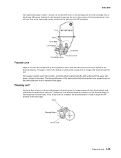
... rotates, it comes into contact with the cleaning blade and collected in the waste toner reservoir. Cleaning unit Any toner that remains on the photoconductor drum to transfer to the paper.
... rotates, it comes into contact with the cleaning blade and collected in the waste toner reservoir. Cleaning unit Any toner that remains on the photoconductor drum to transfer to the paper.
Service Manual
Page 143
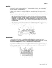
...is replaced or removed. Note: Adjust the printer alignment whenever the belt unit is called color mode. To avoid unnecessary wear of the photosensitive drum by the electromagnetic clutch in drive 1. Furthermore, if the transfer belt is damaged, toner can cling to the switching shaft. Once the image...-XXX Belt unit The transfer belt acts as a transport for the paper as it is carried from the registration rollers, underneath the photoconductor drums, and finally to the separation fingers, where the paper is detached from the belt and then enters the fuser. The density sensor is ...
...is replaced or removed. Note: Adjust the printer alignment whenever the belt unit is called color mode. To avoid unnecessary wear of the photosensitive drum by the electromagnetic clutch in drive 1. Furthermore, if the transfer belt is damaged, toner can cling to the switching shaft. Once the image...-XXX Belt unit The transfer belt acts as a transport for the paper as it is carried from the registration rollers, underneath the photoconductor drums, and finally to the separation fingers, where the paper is detached from the belt and then enters the fuser. The density sensor is ...

Service Manual
Page 163
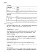
5056-XXX Elevator sequence The wire drum rotates by the driving force of the elevator motor until the elevator upper limit sensor is ON, the paper feeds onto the tray, or until ... the tray. Paper Full Sensor A Belt Paper Upper Level Sensor B Wire Hook Plate Elevator Upper Limit Sensor Belt Drive Motor Elevator Lower Limit Sensor Wire Drum Elevating Motor Diagnostic aids 3-51 The lower tray moves up by the elevator motor as the wire...
5056-XXX Elevator sequence The wire drum rotates by the driving force of the elevator motor until the elevator upper limit sensor is ON, the paper feeds onto the tray, or until ... the tray. Paper Full Sensor A Belt Paper Upper Level Sensor B Wire Hook Plate Elevator Upper Limit Sensor Belt Drive Motor Elevator Lower Limit Sensor Wire Drum Elevating Motor Diagnostic aids 3-51 The lower tray moves up by the elevator motor as the wire...

Service Manual
Page 197
... the two screws of the drive gear unit sensor from the sensor bracket. 5. Remove the three set screws from the sensor cleaner assembly from the drum drive gear sensor assembly. Remove the harness band and remove the two screws from the density sensor from the sensor bracket. 3. Open the top unit...
... the two screws of the drive gear unit sensor from the sensor bracket. 5. Remove the three set screws from the sensor cleaner assembly from the drum drive gear sensor assembly. Remove the harness band and remove the two screws from the density sensor from the sensor bracket. 3. Open the top unit...

Service Manual
Page 202
... board, RIP box, electronic box, and printer controller board. 2. Remove the HVPS board. Open the top unit, remove the top cover, toner cartridges, and photodeveloper drum units. Note: When replacing the rail, be out of focus. 4-20 Service Manual Remove the short black screw from the printer controller board bracket. 3. Remove...
... board, RIP box, electronic box, and printer controller board. 2. Remove the HVPS board. Open the top unit, remove the top cover, toner cartridges, and photodeveloper drum units. Note: When replacing the rail, be out of focus. 4-20 Service Manual Remove the short black screw from the printer controller board bracket. 3. Remove...

Service Manual
Page 206
5056-XXX 14. Remove the E-clip on the right side. 16. Remove the screw from the drive unit, and remove the unit. 17. Remove the three screws from the belt up/down clutch box, and remove the belt up /down clutch. 19. Remove the six screws on the belt up /down clutch, and remove the changing shaft from the clutch stopper. The clutch stopper is attached to the ground plate with two screws. 15. Remove the two screws from the drum gear sensor, and remove the sensor. 4-24 Service Manual Remove the screw from the drive unit. 18.
5056-XXX 14. Remove the E-clip on the right side. 16. Remove the screw from the drive unit, and remove the unit. 17. Remove the three screws from the belt up/down clutch box, and remove the belt up /down clutch. 19. Remove the six screws on the belt up /down clutch, and remove the changing shaft from the clutch stopper. The clutch stopper is attached to the ground plate with two screws. 15. Remove the two screws from the drum gear sensor, and remove the sensor. 4-24 Service Manual Remove the screw from the drive unit. 18.

Service Manual
Page 214
... five screws and two snap bands from the printer. 2. 5056-XXX Face down guide assembly. 3. Open the top unit, and remove the toner cartridges, photodeveloper drum units, and upper cover. 1.
... five screws and two snap bands from the printer. 2. 5056-XXX Face down guide assembly. 3. Open the top unit, and remove the toner cartridges, photodeveloper drum units, and upper cover. 1.

Service Manual
Page 229
Repair information 4-47 Remove the left rear, rear, and right covers. 2. Remove the print controller card and the HVPS. 3. Disconnect the sensor cable from the upper bracket, and remove the bracket. down guide assembly. 2. Remove the four screws and the five screws from CN10 on the CK1 daughter card board. 4. Remove two screws from the turn guide sensor assembly, and remove the sensor. 5056-XXX Upper fan removal 1. Turn guide cover sensor removal 1. Open the top unit, and remove the toner cartridges and photodeveloper drum units, top cover, and face-
Repair information 4-47 Remove the left rear, rear, and right covers. 2. Remove the print controller card and the HVPS. 3. Disconnect the sensor cable from the upper bracket, and remove the bracket. down guide assembly. 2. Remove the four screws and the five screws from CN10 on the CK1 daughter card board. 4. Remove two screws from the turn guide sensor assembly, and remove the sensor. 5056-XXX Upper fan removal 1. Turn guide cover sensor removal 1. Open the top unit, and remove the toner cartridges and photodeveloper drum units, top cover, and face-


