(English) Rescue and Recovery 4.3 Deployment Guide
Page 76
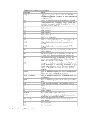
Lenovo-branded preload Only). /OEM Computer is located in the service partition with DOS (dual boot Windows PE and DOS; BMGR32 parameters (continued) Parameter Result /CFGfile Apply the configuration file parameters. See "RRCMD command-line interface" on the keyboard to enter the Predesktop...Master boot record patch. /PRTC Used for installation program only, to retrieve patch return code. /IBM System is an IBM branded or Lenovo-branded computer. /Q Silent. /V Verbose. /R Reboot computer. /REFRESH Reset partition table entries in the C:\PARTITION (dual boot Windows ...
Lenovo-branded preload Only). /OEM Computer is located in the service partition with DOS (dual boot Windows PE and DOS; BMGR32 parameters (continued) Parameter Result /CFGfile Apply the configuration file parameters. See "RRCMD command-line interface" on the keyboard to enter the Predesktop...Master boot record patch. /PRTC Used for installation program only, to retrieve patch return code. /IBM System is an IBM branded or Lenovo-branded computer. /Q Silent. /V Verbose. /R Reboot computer. /REFRESH Reset partition table entries in the C:\PARTITION (dual boot Windows ...
(English) Rescue and Recovery 4.5 Deployment Guide
Page 66
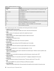
...; Data Sector number of ¼ seconds to wait if the F11 message is stored. • IBM Flag Value from the data sector (1 if Lenovo-branded system, 0 if not) • Boot Config Displays the installation option used to the service area. The scan code for the F11 key is... area. 60 Rescue and Recovery 4.5 Deployment Guide BMGR32 parameters (continued) Parameter Result /THINK Configure the boot manager to use the blue button on the keyboard to enter the Predesktop Area. /TOC tocvalue Set the BIOS TOC location (16 characters that represent 8 bytes of data). /U0 Show partition 0. ...
...; Data Sector number of ¼ seconds to wait if the F11 message is stored. • IBM Flag Value from the data sector (1 if Lenovo-branded system, 0 if not) • Boot Config Displays the installation option used to the service area. The scan code for the F11 key is... area. 60 Rescue and Recovery 4.5 Deployment Guide BMGR32 parameters (continued) Parameter Result /THINK Configure the boot manager to use the blue button on the keyboard to enter the Predesktop Area. /TOC tocvalue Set the BIOS TOC location (16 characters that represent 8 bytes of data). /U0 Show partition 0. ...
(English) Power Manager Deployment Guide
Page 28
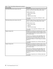
...and users select On from the pull-down menu, the Windows operating system will automatically adjust the setting based on what users do with their keyboard or mouse to keep the computer display on Windows Vista client computers. This setting is only supported on Windows 7 client computers. This setting ... select On from the pull-down menu, the Windows operating system will automatically adjust the setting based on what users do with their keyboard or mouse to keep the computer display on Windows Vista client computers. 22 Power ManagerDeployment Guide Table 2.
...and users select On from the pull-down menu, the Windows operating system will automatically adjust the setting based on what users do with their keyboard or mouse to keep the computer display on Windows Vista client computers. This setting is only supported on Windows 7 client computers. This setting ... select On from the pull-down menu, the Windows operating system will automatically adjust the setting based on what users do with their keyboard or mouse to keep the computer display on Windows Vista client computers. 22 Power ManagerDeployment Guide Table 2.
Hardware Maintenance Manual
Page 3
...33 Restoring the factory contents by using PC-Doctor for DOS. . . . 24 Lenovo ThinkVantage Toolbox (Lenovo System Toolbox 27 PC-Doctor for Windows 27 PC-Doctor for replacing a system board... backup battery 30 Chapter 4. Removing and replacing a FRU 59 Before servicing ThinkPad X200 Tablet and X201 Tablet 60 1010 Digitizer pen 61 1020 Battery pack 61 1030 Hard disk... drive (HDD) cover, HDD, and HDD rubber rails or solid state drive (SSD) and storage converter 62 1040 DIMM 65 1050 Hinge caps 67 1060 Keyboard...
...33 Restoring the factory contents by using PC-Doctor for DOS. . . . 24 Lenovo ThinkVantage Toolbox (Lenovo System Toolbox 27 PC-Doctor for Windows 27 PC-Doctor for replacing a system board... backup battery 30 Chapter 4. Removing and replacing a FRU 59 Before servicing ThinkPad X200 Tablet and X201 Tablet 60 1010 Digitizer pen 61 1020 Battery pack 61 1030 Hard disk... drive (HDD) cover, HDD, and HDD rubber rails or solid state drive (SSD) and storage converter 62 1040 DIMM 65 1050 Hinge caps 67 1060 Keyboard...

Hardware Maintenance Manual
Page 4
...antenna cables 117 Chapter 9. Locations 123 Front view 123 Rear view 124 Rear view (tablet mode 125 Bottom view 126 Rear view (ThinkPad X200 UltraBase 126 Bottom view (ThinkPad X200 UltraBase). . . . . 127 Chapter 10. Parts list 129 Overall 130 LCD FRUs for touch panel LCD or direct-bonding... glass LCD 155 LCD FRUs for protection plate LCD 164 Keyboard 172 Miscellaneous parts 173 AC adapters 175 Power cords 175 Recovery discs ...
...antenna cables 117 Chapter 9. Locations 123 Front view 123 Rear view 124 Rear view (tablet mode 125 Bottom view 126 Rear view (ThinkPad X200 UltraBase 126 Bottom view (ThinkPad X200 UltraBase). . . . . 127 Chapter 10. Parts list 129 Overall 130 LCD FRUs for touch panel LCD or direct-bonding... glass LCD 155 LCD FRUs for protection plate LCD 164 Keyboard 172 Miscellaneous parts 173 AC adapters 175 Power cords 175 Recovery discs ...
Hardware Maintenance Manual
Page 30
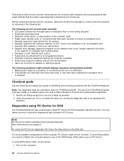
...are not covered under warranty and some possible configurations of errors and invalid system responses. 1. Verify the symptoms. Try to test only ThinkPad products. Note: The diagnostic tests are not covered under the warranty by referring to the following list: The following are intended to...available at the following symptoms might indicate damage caused by spilling a liquid onto the keyboard • Use of an incorrect ac adapter on laptop products The following Web site: http://www.lenovo.com/support To create the PC-Doctor diagnostic CD, follow the instructions on the ...
...are not covered under warranty and some possible configurations of errors and invalid system responses. 1. Verify the symptoms. Try to test only ThinkPad products. Note: The diagnostic tests are not covered under the warranty by referring to the following list: The following are intended to...available at the following symptoms might indicate damage caused by spilling a liquid onto the keyboard • Use of an incorrect ac adapter on laptop products The following Web site: http://www.lenovo.com/support To create the PC-Doctor diagnostic CD, follow the instructions on the ...

Hardware Maintenance Manual
Page 32
... test Digital Signature Chip, the security chip must be set to Active. • To test Serial Ports or Parallel Ports, the ThinkPad Notebook must be held down for at least 2 seconds; Diagnostics Interactive Tests • Run Normal Test • Run Quick Test ...• Systemboard • Video Adapter • Fixed Disks • Diskette Drives • Other Devices • ThinkPad Devices • Communication • Wireless LAN • Advanced Memory Tests • Keyboard • Video • Internal Speaker • Mouse • Diskette • System Load • Optical Drive...
... test Digital Signature Chip, the security chip must be set to Active. • To test Serial Ports or Parallel Ports, the ThinkPad Notebook must be held down for at least 2 seconds; Diagnostics Interactive Tests • Run Normal Test • Run Quick Test ...• Systemboard • Video Adapter • Fixed Disks • Diskette Drives • Other Devices • ThinkPad Devices • Communication • Wireless LAN • Advanced Memory Tests • Keyboard • Video • Internal Speaker • Mouse • Diskette • System Load • Optical Drive...
Hardware Maintenance Manual
Page 34
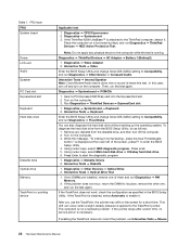
... to Compatibility, and run the test again. Insert a PCI-Express/USB Wrap card into the ExpressCard slot. 2. Diagnostics ➙ Systemboard ➙ Keyboard 2. Interactive Tests ➙ Keyboard Enter the BIOS Setup Utility and change Serial ATA (SATA) setting to the ThinkPad computer, detach it . Remove any physical shock to Compatibility, and run Diagnostics ➙...
... to Compatibility, and run the test again. Insert a PCI-Express/USB Wrap card into the ExpressCard slot. 2. Diagnostics ➙ Systemboard ➙ Keyboard 2. Interactive Tests ➙ Keyboard Enter the BIOS Setup Utility and change Serial ATA (SATA) setting to the ThinkPad computer, detach it . Remove any physical shock to Compatibility, and run Diagnostics ➙...

Hardware Maintenance Manual
Page 43
... by changing the settings in Windows XP, keep current power scheme). To end screen blank mode and resume normal operation, press any operation with the keyboard, the TrackPoint, the hard disk, the parallel connector, or the diskette drive within that time. • If the battery indicator blinks orange, indicating that the...
... by changing the settings in Windows XP, keep current power scheme). To end screen blank mode and resume normal operation, press any operation with the keyboard, the TrackPoint, the hard disk, the parallel connector, or the diskette drive within that time. • If the battery indicator blinks orange, indicating that the...

Hardware Maintenance Manual
Page 44
... errors and their possible causes. The most likely cause is turned on the timer, and if the user does not do any operation with the keyboard, the TrackPoint, the hard disk drive, the parallel connector, or the diskette drive within that action. - Do not replace a nondefective FRU. Hibernation mode In hibernation...
... errors and their possible causes. The most likely cause is turned on the timer, and if the user does not do any operation with the keyboard, the TrackPoint, the hard disk drive, the parallel connector, or the diskette drive within that action. - Do not replace a nondefective FRU. Hibernation mode In hibernation...
Hardware Maintenance Manual
Page 46
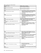
...security chip has failed. Remove one Wireless LAN devices are found . System board. 0200 Hard disk error-The hard disk is not working. 021x Keyboard error. 40 Hardware Maintenance Manual 1. Remove all but one of them . Enter the supervisor password. 1. Confirm the operation and try again. ... or more Ethernet devices are found . System board. Press to continue. 01CA More than one of them . 1. Remove one of the keyboard and the auxiliary input device. System board. 1. Numeric error codes (continued) Symptom or error 0193 RF antenna has been removed 0194 The ...
...security chip has failed. Remove one Wireless LAN devices are found . System board. 0200 Hard disk error-The hard disk is not working. 021x Keyboard error. 40 Hardware Maintenance Manual 1. Remove all but one of them . Enter the supervisor password. 1. Confirm the operation and try again. ... or more Ethernet devices are found . System board. Press to continue. 01CA More than one of them . 1. Remove one of the keyboard and the auxiliary input device. System board. 1. Numeric error codes (continued) Symptom or error 0193 RF antenna has been removed 0194 The ...
Hardware Maintenance Manual
Page 56
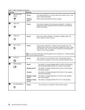
... hold the Shift key, and press the NumLk (ScrLk) key. 5 Caps lock Green: Caps Lock mode is being transmitted. Green: The computer is on the keyboard is charged between 5% and 20% of the capacity, and being discharged. The battery is enabled. The numeric keypad on and ready to the hard disk...
... hold the Shift key, and press the NumLk (ScrLk) key. 5 Caps lock Green: Caps Lock mode is being transmitted. Green: The computer is on the keyboard is charged between 5% and 20% of the capacity, and being discharged. The battery is enabled. The numeric keypad on and ready to the hard disk...
Hardware Maintenance Manual
Page 74
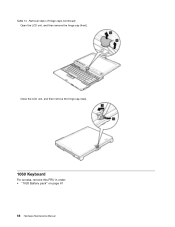
Close the LCD unit, and then remove the hinge cap (rear). 1060 Keyboard For access, remove this FRU in order: • "1020 Battery pack" on page 61 68 Hardware Maintenance Manual Table 13. Removal steps of hinge caps (continued) Open the LCD unit, and then remove the hinge cap (front).
Close the LCD unit, and then remove the hinge cap (rear). 1060 Keyboard For access, remove this FRU in order: • "1020 Battery pack" on page 61 68 Hardware Maintenance Manual Table 13. Removal steps of hinge caps (continued) Open the LCD unit, and then remove the hinge cap (front).
Hardware Maintenance Manual
Page 75
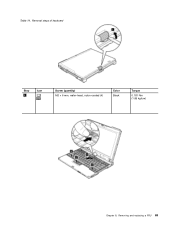
Table 14. Removing and replacing a FRU 69 Removal steps of keyboard Step 1 Icon Screw (quantity) M2 × 6 mm, wafer-head, nylon-coated (4) Color Black Torque 0.181 Nm (1.85 kgfcm) Chapter 8.
Table 14. Removing and replacing a FRU 69 Removal steps of keyboard Step 1 Icon Screw (quantity) M2 × 6 mm, wafer-head, nylon-coated (4) Color Black Torque 0.181 Nm (1.85 kgfcm) Chapter 8.
Hardware Maintenance Manual
Page 76
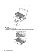
Table 14. Make sure that the keyboard edges are under the frame as shown in place. 70 Hardware Maintenance Manual Then press the keys to latch the keyboard firmly in this figure. When installing: 1. Attach the keyboard connector firmly. 2. Removal steps of keyboard (continued) Lift the keyboard a little in the direction shown by arrow 4 , and then detach the connector 5 .
Table 14. Make sure that the keyboard edges are under the frame as shown in place. 70 Hardware Maintenance Manual Then press the keys to latch the keyboard firmly in this figure. When installing: 1. Attach the keyboard connector firmly. 2. Removal steps of keyboard (continued) Lift the keyboard a little in the direction shown by arrow 4 , and then detach the connector 5 .

Hardware Maintenance Manual
Page 77
Removal steps of the computer. 1070 Extension cable card For access, remove these FRUs in order: • "1020 Battery pack" on page 61 • "1060 Keyboard" on page 68 Chapter 8. Secure the keyboard by tightening the screws from the bottom side of keyboard (continued) 3. Removing and replacing a FRU 71 Table 14. To make sure that the front side of the keyboard is housed firmly, gently press the keys with your thumbs and try to slide the keyboard toward you. 4.
Removal steps of the computer. 1070 Extension cable card For access, remove these FRUs in order: • "1020 Battery pack" on page 61 • "1060 Keyboard" on page 68 Chapter 8. Secure the keyboard by tightening the screws from the bottom side of keyboard (continued) 3. Removing and replacing a FRU 71 Table 14. To make sure that the front side of the keyboard is housed firmly, gently press the keys with your thumbs and try to slide the keyboard toward you. 4.

Hardware Maintenance Manual
Page 78
Table 15. Color Black Silver Torque 0.181 Nm (1.85 kgfcm) 0.181 Nm (1.85 kgfcm) 1080 Palm rest For access, remove this FRU in order: • "1020 Battery pack" on page 61 • "1060 Keyboard" on page 68 72 Hardware Maintenance Manual Removal steps of Extension cable card Step 1 2 Screw (quantity) M2 × 3 mm, flat-head, nylon-coated (5) M2 × 6 mm, flat-head, nylon-coated (2) When installing: Make sure that the connectors are attached firmly.
Table 15. Color Black Silver Torque 0.181 Nm (1.85 kgfcm) 0.181 Nm (1.85 kgfcm) 1080 Palm rest For access, remove this FRU in order: • "1020 Battery pack" on page 61 • "1060 Keyboard" on page 68 72 Hardware Maintenance Manual Removal steps of Extension cable card Step 1 2 Screw (quantity) M2 × 3 mm, flat-head, nylon-coated (5) M2 × 6 mm, flat-head, nylon-coated (2) When installing: Make sure that the connectors are attached firmly.

Hardware Maintenance Manual
Page 81
Removing and replacing a FRU 75 For access, remove these FRUs in the parts list for your computer. Any other battery could ignite or explode. Removal steps of backup battery Chapter 8. 1090 Backup battery DANGER Use only the battery specified in order: • "1020 Battery pack" on page 61 • "1060 Keyboard" on page 68 • "1080 Palm rest" on page 72 Table 17.
Removing and replacing a FRU 75 For access, remove these FRUs in the parts list for your computer. Any other battery could ignite or explode. Removal steps of backup battery Chapter 8. 1090 Backup battery DANGER Use only the battery specified in order: • "1020 Battery pack" on page 61 • "1060 Keyboard" on page 68 • "1080 Palm rest" on page 72 Table 17.

Hardware Maintenance Manual
Page 82
Removal steps of the arrow. Note: Some models might have two antenna cables in order: • "1020 Battery pack" on page 61 • "1060 Keyboard" on page 68 • "1080 Palm rest" on page 72 Table 18. Step 2 Screw (quantity) M2 × 3.5 mm, wafer-head, nylon-coated (2) Color Silver Torque 0....
Removal steps of the arrow. Note: Some models might have two antenna cables in order: • "1020 Battery pack" on page 61 • "1060 Keyboard" on page 68 • "1080 Palm rest" on page 72 Table 18. Step 2 Screw (quantity) M2 × 3.5 mm, wafer-head, nylon-coated (2) Color Silver Torque 0....

Hardware Maintenance Manual
Page 84
... AUX. 1110 PCI Express Mini Card for wireless WAN For access, remove these FRUs in order: • "1020 Battery pack" on page 61 • "1060 Keyboard" on page 68 • "1080 Palm rest" on page 72 Table 19.
... AUX. 1110 PCI Express Mini Card for wireless WAN For access, remove these FRUs in order: • "1020 Battery pack" on page 61 • "1060 Keyboard" on page 68 • "1080 Palm rest" on page 72 Table 19.


