Hardware Maintenance Manual
Page 3
.... . 55 Chapter 8. Removing and replacing a FRU 57 Before servicing ThinkPad X1 and X1 Hybrid models 58 1000 Disabling the battery pack in the UEFI BIOS 58 1010 Hard disk drive and solid state drive . . . . 59 1020 Keyboard 61 1030 DIMM 64 1040 Backup battery 65 1050 PCI Express Mini Card...replacing FRUs 23 Strategy for replacing a hard disk drive . . . 24 Important notice for DOS diagnostics program 28 System supporting the Lenovo diagnostics programs 32 Power system checkout 34 Checking the ac power adapter 34 Checking operational charging 35 Checking the battery pack 35 Checking ...
.... . 55 Chapter 8. Removing and replacing a FRU 57 Before servicing ThinkPad X1 and X1 Hybrid models 58 1000 Disabling the battery pack in the UEFI BIOS 58 1010 Hard disk drive and solid state drive . . . . 59 1020 Keyboard 61 1030 DIMM 64 1040 Backup battery 65 1050 PCI Express Mini Card...replacing FRUs 23 Strategy for replacing a hard disk drive . . . 24 Important notice for DOS diagnostics program 28 System supporting the Lenovo diagnostics programs 32 Power system checkout 34 Checking the ac power adapter 34 Checking operational charging 35 Checking the battery pack 35 Checking ...

Hardware Maintenance Manual
Page 4
Parts list 97 Overall 98 LCD FRUs 107 Keyboard 108 Miscellaneous parts 109 ac power adapters 110 Power cords 111 Recovery discs 112 Windows 7 Home Basic (64-bit) DVDs . . . 112 Windows 7 Home Premium (32-...
Parts list 97 Overall 98 LCD FRUs 107 Keyboard 108 Miscellaneous parts 109 ac power adapters 110 Power cords 111 Recovery discs 112 Windows 7 Home Basic (64-bit) DVDs . . . 112 Windows 7 Home Premium (32-...
Hardware Maintenance Manual
Page 34
...program menu appears after the password is available at the following Web site: http://www.lenovo.com/support. To enter the ThinkPad Setup program, do as possible. 2. The use of the ThinkPad Setup program before you need to initialize the computer setup by pressing Enter instead of...attachment of a nonsupported device • Forgotten computer password (making the computer unusable) • Sticky keys caused by spilling a liquid onto the keyboard • Use of an incorrect ac adapter on the computer. 2. The following are not covered under warranty: • LCD panel cracked from...
...program menu appears after the password is available at the following Web site: http://www.lenovo.com/support. To enter the ThinkPad Setup program, do as possible. 2. The use of the ThinkPad Setup program before you need to initialize the computer setup by pressing Enter instead of...attachment of a nonsupported device • Forgotten computer password (making the computer unusable) • Sticky keys caused by spilling a liquid onto the keyboard • Use of an incorrect ac adapter on the computer. 2. The following are not covered under warranty: • LCD panel cracked from...
Hardware Maintenance Manual
Page 36
...• Video Adapter • Fixed Disks • Diskette Drives • Other Devices • Communication • Wireless LAN • Keyboard • Video • Internal Speaker • Mouse • Diskette • System Load • Optical Drive Test • Intel...• Tech Support Form • Battery Rundown • Erase Drive Contents • View PCDR Host Log Lenovo ThinkVantage Toolbox Lenovo ThinkVantage® Toolbox is a problem, PC-Doctor shows messages describing it cannot be selected. 10. To cancel..., check the time and date on the ThinkPad Notebook.
...• Video Adapter • Fixed Disks • Diskette Drives • Other Devices • Communication • Wireless LAN • Keyboard • Video • Internal Speaker • Mouse • Diskette • System Load • Optical Drive Test • Intel...• Tech Support Form • Battery Rundown • Erase Drive Contents • View PCDR Host Log Lenovo ThinkVantage Toolbox Lenovo ThinkVantage® Toolbox is a problem, PC-Doctor shows messages describing it cannot be selected. 10. To cancel..., check the time and date on the ThinkPad Notebook.
Hardware Maintenance Manual
Page 37
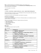
...Turn on the screen. System Health and Diagnostics. Diagnostics ➙ Systemboard Diagnostics ➙ ThinkPad Devices ➙ ac Adapter, Battery 1 (Battery 2) 1. Lenovo ThinkVantage Toolbox also has problem determination aids that determine software and usage problems. For additional... Lenovo ThinkVantage Toolbox on the computer, go to Compatibility, and run Diagnostics ➙ Fixed Disks. 1. To run this test again. Follow the instructions on the computer. 3. Diagnostics ➙ Systemboard ➙ Keyboard 2. Interactive Tests ➙ Keyboard Enter the ThinkPad...
...Turn on the screen. System Health and Diagnostics. Diagnostics ➙ Systemboard Diagnostics ➙ ThinkPad Devices ➙ ac Adapter, Battery 1 (Battery 2) 1. Lenovo ThinkVantage Toolbox also has problem determination aids that determine software and usage problems. For additional... Lenovo ThinkVantage Toolbox on the computer, go to Compatibility, and run Diagnostics ➙ Fixed Disks. 1. To run this test again. Follow the instructions on the computer. 3. Diagnostics ➙ Systemboard ➙ Keyboard 2. Interactive Tests ➙ Keyboard Enter the ThinkPad...
Hardware Maintenance Manual
Page 47
... . Note: If the computer is low, and then the computer enters the power-saving mode automatically. Note: Even if you do any operation with the keyboard, the TrackPoint, the hard disk, the parallel connector, or the diskette drive within that time. • If the battery indicator blinks orange, indicating that action...
... . Note: If the computer is low, and then the computer enters the power-saving mode automatically. Note: Even if you do any operation with the keyboard, the TrackPoint, the hard disk, the parallel connector, or the diskette drive within that time. • If the battery indicator blinks orange, indicating that action...

Hardware Maintenance Manual
Page 48
...replace a nondefective FRU. Numeric error codes Symptom or error 0177 Bad SVP data, stop POST task-The checksum of the CRS2 setting in the ThinkPad notebooks, see the manual for that time. • If the timer conditions are likely to need to -FRU index in the EEPROM is...index This section contains following conditions: • If a "hibernation time" has been set on page 46 The symptom-to be any operation with the keyboard, the TrackPoint, the hard disk drive, the parallel connector, or the diskette drive within that device. In the displays, n can also help you determine...
...replace a nondefective FRU. Numeric error codes Symptom or error 0177 Bad SVP data, stop POST task-The checksum of the CRS2 setting in the ThinkPad notebooks, see the manual for that time. • If the timer conditions are likely to need to -FRU index in the EEPROM is...index This section contains following conditions: • If a "hibernation time" has been set on page 46 The symptom-to be any operation with the keyboard, the TrackPoint, the hard disk drive, the parallel connector, or the diskette drive within that device. In the displays, n can also help you determine...

Hardware Maintenance Manual
Page 58
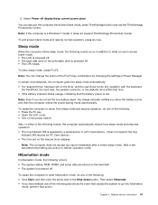
...Fn+F11 Fn+F12 Fn+Spacebar The purpose of the Power Option in Instant Media Mode. Press Fn+Spacebar once to turn on the keyboard backlight in Instant Media Mode Key combination Description Esc Go back to change the settings of this method is to the previous page. ... level temporarily. To change the default brightness level, change the brightness level temporarily. There are three states for a third time turns off the keyboard backlight. Fn+F9 The purpose of some function keys in Control Panel or use Power Manager. The computer display becomes brighter. Previous track or ...
...Fn+F11 Fn+F12 Fn+Spacebar The purpose of the Power Option in Instant Media Mode. Press Fn+Spacebar once to turn on the keyboard backlight in Instant Media Mode Key combination Description Esc Go back to change the settings of this method is to the previous page. ... level temporarily. To change the default brightness level, change the brightness level temporarily. There are three states for a third time turns off the keyboard backlight. Fn+F9 The purpose of some function keys in Control Panel or use Power Manager. The computer display becomes brighter. Previous track or ...

Hardware Maintenance Manual
Page 67
...disk drive rubber rails or solid state drive spacers are attached firmly. 1020 Keyboard For access, disable the battery pack first. Then, lift up the keyboard in the direction shown by the arrow 3 . 3 2 2 2 Lift the keyboard in the direction shown by the arrow 2 , to "1000 Disabling ...the battery pack in the direction shown by the arrow 4 , and then detach the connectors. Removal steps of the keyboard from the frame. Chapter 8. Refer to detach the front edge of keyboard 1 1 Step 1 Screw (quantity) M2 x 5 mm (2) Color Black Torque 0.181 Nm (1.85 kgfcm) Slightly press ...
...disk drive rubber rails or solid state drive spacers are attached firmly. 1020 Keyboard For access, disable the battery pack first. Then, lift up the keyboard in the direction shown by the arrow 3 . 3 2 2 2 Lift the keyboard in the direction shown by the arrow 2 , to "1000 Disabling ...the battery pack in the direction shown by the arrow 4 , and then detach the connectors. Removal steps of the keyboard from the frame. Chapter 8. Refer to detach the front edge of keyboard 1 1 Step 1 Screw (quantity) M2 x 5 mm (2) Color Black Torque 0.181 Nm (1.85 kgfcm) Slightly press ...

Hardware Maintenance Manual
Page 68
Attach the keyboard so that the keyboard edge a is under the frame as shown in the direction shown by the arrow 5 4 3 2 1 5 2. 7 8 5 6 4 When installing: 1. Attach the keyboard connectors firmly. Then lift the keyboard in the following figure. 62 Hardware Maintenance Manual
Attach the keyboard so that the keyboard edge a is under the frame as shown in the direction shown by the arrow 5 4 3 2 1 5 2. 7 8 5 6 4 When installing: 1. Attach the keyboard connectors firmly. Then lift the keyboard in the following figure. 62 Hardware Maintenance Manual

Hardware Maintenance Manual
Page 69
Removing and replacing a FRU 63 a a 3. Chapter 8. Gently press the keys with your palms and try to slide the keyboard toward you until it snaps into position. 4. Make sure that the front edge of the keyboard b is attached firmly.
Removing and replacing a FRU 63 a a 3. Chapter 8. Gently press the keys with your palms and try to slide the keyboard toward you until it snaps into position. 4. Make sure that the front edge of the keyboard b is attached firmly.

Hardware Maintenance Manual
Page 70
Secure the keyboard by tightening the screws on the bottom side of the DIMM into place. Refer to "1000 Disabling the battery pack in the slot and does not move easily. 64 Hardware Maintenance Manual b 5. Press the DIMM firmly, and pivot it until it is firmly installed in the UEFI BIOS" on page 61 Removal steps of DIMM 1 1 2 When installing: Insert the notched end of the computer. 1030 DIMM For access, disable the battery pack first. Then remove this FRU: • "1020 Keyboard" on page 58 for detailed instructions. Make sure that it snaps into the socket.
Secure the keyboard by tightening the screws on the bottom side of the DIMM into place. Refer to "1000 Disabling the battery pack in the slot and does not move easily. 64 Hardware Maintenance Manual b 5. Press the DIMM firmly, and pivot it until it is firmly installed in the UEFI BIOS" on page 61 Removal steps of DIMM 1 1 2 When installing: Insert the notched end of the computer. 1030 DIMM For access, disable the battery pack first. Then remove this FRU: • "1020 Keyboard" on page 58 for detailed instructions. Make sure that it snaps into the socket.

Hardware Maintenance Manual
Page 71
... steps of PCI Express Mini Card for wireless LAN/WiMAX Note: Some models might have only two antenna cables. Then remove this FRU: • "1020 Keyboard" on page 58 for detailed instructions. Refer to "1000 Disabling the battery pack in the UEFI BIOS" on page 61 Removal steps of backup battery... your fingers and gently unplug them in the direction of the arrows. Any other battery could ignite or explode. Then remove this FRU: • "1020 Keyboard" on page 58 for detailed instructions.
... steps of PCI Express Mini Card for wireless LAN/WiMAX Note: Some models might have only two antenna cables. Then remove this FRU: • "1020 Keyboard" on page 58 for detailed instructions. Refer to "1000 Disabling the battery pack in the UEFI BIOS" on page 61 Removal steps of backup battery... your fingers and gently unplug them in the direction of the arrows. Any other battery could ignite or explode. Then remove this FRU: • "1020 Keyboard" on page 58 for detailed instructions.

Hardware Maintenance Manual
Page 73
... card. 1060 PCI Express Mini Card for detailed instructions. Removing and replacing a FRU 67 Refer to "1000 Disabling the battery pack in order: • "1020 Keyboard" on page 58 for wireless WAN For access, disable the battery pack first. Then remove this FRU in the UEFI BIOS" on page 61 Removal...
... card. 1060 PCI Express Mini Card for detailed instructions. Removing and replacing a FRU 67 Refer to "1000 Disabling the battery pack in order: • "1020 Keyboard" on page 58 for wireless WAN For access, disable the battery pack first. Then remove this FRU in the UEFI BIOS" on page 61 Removal...

Hardware Maintenance Manual
Page 74
... system is operating or is sensitive to "1000 Disabling the battery pack in suspend mode. 68 Hardware Maintenance Manual Then remove this FRU: • "1020 Keyboard" on it . Refer to physical shock. The mSATA solid state drive is in the UEFI BIOS" on the card, and the blue cable into the...
... system is operating or is sensitive to "1000 Disabling the battery pack in suspend mode. 68 Hardware Maintenance Manual Then remove this FRU: • "1020 Keyboard" on it . Refer to physical shock. The mSATA solid state drive is in the UEFI BIOS" on the card, and the blue cable into the...

Hardware Maintenance Manual
Page 75
Then remove this FRU: • "1020 Keyboard" on page 58 for detailed instructions. Refer to "1000 Disabling the battery pack in the UEFI BIOS" on page 61 Chapter 8. Removing and replacing a FRU 69 Removal steps of mSATA solid state drive 1 Step 1 Screw (quantity) M2 x 3 mm (1) Color Black Torque 0.181 Nm (1.85 kgfcm) 2 1080 Instant Media Mode card For access, disable the battery pack first.
Then remove this FRU: • "1020 Keyboard" on page 58 for detailed instructions. Refer to "1000 Disabling the battery pack in the UEFI BIOS" on page 61 Chapter 8. Removing and replacing a FRU 69 Removal steps of mSATA solid state drive 1 Step 1 Screw (quantity) M2 x 3 mm (1) Color Black Torque 0.181 Nm (1.85 kgfcm) 2 1080 Instant Media Mode card For access, disable the battery pack first.

Hardware Maintenance Manual
Page 76
When installing: Plug the red cable in the Instant Media Mode card jack. 2. Remove the keyboard bezel assembly. Removal steps of Instant Media Mode card 1. See "1090 Keyboard bezel assembly with fingerprint reader and audio sub card " on page 71. 3. Disconnect the WLAN cable. Disconnect the Instant Media Mode card cable and remove the screw. 70 Hardware Maintenance Manual
When installing: Plug the red cable in the Instant Media Mode card jack. 2. Remove the keyboard bezel assembly. Removal steps of Instant Media Mode card 1. See "1090 Keyboard bezel assembly with fingerprint reader and audio sub card " on page 71. 3. Disconnect the WLAN cable. Disconnect the Instant Media Mode card cable and remove the screw. 70 Hardware Maintenance Manual

Hardware Maintenance Manual
Page 77
Chapter 8. Removing and replacing a FRU 71 Color Black Torque 0.181 Nm (1.85 kgfcm) 1090 Keyboard bezel assembly with fingerprint reader and audio sub card For access, disable the battery pack first. Refer to "1000 Disabling the battery pack in the UEFI BIOS" on page 58 for future use. Remove the card and save it for detailed instructions. The card pops up. 1 2 Step 3 Screw (quantity) M2 x 3mm (1) 4.
Chapter 8. Removing and replacing a FRU 71 Color Black Torque 0.181 Nm (1.85 kgfcm) 1090 Keyboard bezel assembly with fingerprint reader and audio sub card For access, disable the battery pack first. Refer to "1000 Disabling the battery pack in the UEFI BIOS" on page 58 for future use. Remove the card and save it for detailed instructions. The card pops up. 1 2 Step 3 Screw (quantity) M2 x 3mm (1) 4.

Hardware Maintenance Manual
Page 78
Removal steps of keyboard bezel with the fingerprint reader, the sensor is attached to the palm rest FRU. Then remove these FRUs in this section, which are the same ..., you can replace it by following the procedures given in order: • "1010 Hard disk drive and solid state drive" on page 59 • "1020 Keyboard" on page 61 Note: In models with fingerprint reader 22 1 1 1 1 1 2 1 1 Step 1 2 Screw (quantity) M2 x 5 mm (7) M2 x 3 mm (3) Color Black Black Torque 0.181 Nm (1.85 kgfcm...
Removal steps of keyboard bezel with the fingerprint reader, the sensor is attached to the palm rest FRU. Then remove these FRUs in this section, which are the same ..., you can replace it by following the procedures given in order: • "1010 Hard disk drive and solid state drive" on page 59 • "1020 Keyboard" on page 61 Note: In models with fingerprint reader 22 1 1 1 1 1 2 1 1 Step 1 2 Screw (quantity) M2 x 5 mm (7) M2 x 3 mm (3) Color Black Black Torque 0.181 Nm (1.85 kgfcm...

Hardware Maintenance Manual
Page 80
..., disable the battery pack first. Then remove these FRUs in order: • "1010 Hard disk drive and solid state drive" on page 59 • "1020 Keyboard" on page 58 for detailed instructions. Note that the replacement of battery pack DANGER Use only the battery specified in the parts list for detailed... not covered by the warranty. Then remove these FRUs in order: • "1010 Hard disk drive and solid state drive" on page 59 • "1020 Keyboard" on page 61 • "1090 Keyboard bezel assembly with fingerprint reader and audio sub card " on page 58 for your computer.
..., disable the battery pack first. Then remove these FRUs in order: • "1010 Hard disk drive and solid state drive" on page 59 • "1020 Keyboard" on page 58 for detailed instructions. Note that the replacement of battery pack DANGER Use only the battery specified in the parts list for detailed... not covered by the warranty. Then remove these FRUs in order: • "1010 Hard disk drive and solid state drive" on page 59 • "1020 Keyboard" on page 61 • "1090 Keyboard bezel assembly with fingerprint reader and audio sub card " on page 58 for your computer.


