(English) Power Manager Deployment Guide
Page 28
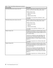
... and users select On from the pull-down menu, the Windows operating system will automatically adjust the setting based on what users do with their keyboard or mouse to keep the computer display on . Possible values include: • Optimize video quality • Balanced • Optimize power savings This setting is only... and users select On from the pull-down menu, the Windows operating system will automatically adjust the setting based on what users do with their keyboard or mouse to keep the computer display on .
... and users select On from the pull-down menu, the Windows operating system will automatically adjust the setting based on what users do with their keyboard or mouse to keep the computer display on . Possible values include: • Optimize video quality • Balanced • Optimize power savings This setting is only... and users select On from the pull-down menu, the Windows operating system will automatically adjust the setting based on what users do with their keyboard or mouse to keep the computer display on .
(Simplified Chinese) Lenovo AutoLock Deployment Guide
Page 12
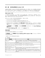
...22312;运行 Active Directory gpedit.msc C:\Windows\PolicyDefinitions ADMX 文件。 5 Lenovo ThinkVantage 6. 展开 Lenovo ThinkVantage AutoLock 常规设置 AutoLock Lenovo ThinkVantage 组件 ➙ AutoLock Windows 7 表 1 策略设...;置 描述 Define second(s) to display notification Define Lenovo AutoLock execution AutoLock。 Define second(s) to begin camera detection from when the keyboard or mouse is not in use Define the behavior when the ...
...22312;运行 Active Directory gpedit.msc C:\Windows\PolicyDefinitions ADMX 文件。 5 Lenovo ThinkVantage 6. 展开 Lenovo ThinkVantage AutoLock 常规设置 AutoLock Lenovo ThinkVantage 组件 ➙ AutoLock Windows 7 表 1 策略设...;置 描述 Define second(s) to display notification Define Lenovo AutoLock execution AutoLock。 Define second(s) to begin camera detection from when the keyboard or mouse is not in use Define the behavior when the ...

(Japanese) Lenovo AutoLock Deployment Guide
Page 13
表 1 Define second(s) to display notification 説明 Define Lenovo AutoLock execution Define second(s) to begin camera detection from when the keyboard or mouse is not in use AutoLock Define the behavior when the camera is disabled AutoLock Define second(s) to lock computer when no facial feature is detected for Turn off the automatic lock function 2 while a second display is connected AutoLock Display notification before the computer automatically locks 6 Lenovo AutoLock
表 1 Define second(s) to display notification 説明 Define Lenovo AutoLock execution Define second(s) to begin camera detection from when the keyboard or mouse is not in use AutoLock Define the behavior when the camera is disabled AutoLock Define second(s) to lock computer when no facial feature is detected for Turn off the automatic lock function 2 while a second display is connected AutoLock Display notification before the computer automatically locks 6 Lenovo AutoLock
(English) Lenovo AutoLock Deployment Guide
Page 13
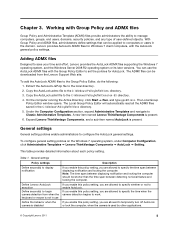
...➙ Run, and type gpedit.msc. To configure general setting policies on the Windows 7 operating system, under Computer Configuration, click Administrative Templates ➙ Lenovo ThinkVantage Components ➙ AutoLock ➙ Setting. If you enable this policy setting, you are allowed to specify whether or not to work. With Group ... to the local directory. 2. Note: The time span between displaying notification and locking the computer should be downloaded from when the keyboard or mouse is not in use the AutoLock ADMX files with the AutoLock general policy settings.
...➙ Run, and type gpedit.msc. To configure general setting policies on the Windows 7 operating system, under Computer Configuration, click Administrative Templates ➙ Lenovo ThinkVantage Components ➙ AutoLock ➙ Setting. If you enable this policy setting, you are allowed to specify whether or not to work. With Group ... to the local directory. 2. Note: The time span between displaying notification and locking the computer should be downloaded from when the keyboard or mouse is not in use the AutoLock ADMX files with the AutoLock general policy settings.
(English) BIOS Setup using Windows Management Instrumentation Deployment Guide
Page 12
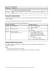
Table 2. Table 3. Password parameters format, password authentication Parameter Description Parameter Current password 1 Parameter Password encoding 2 Parameter Keyboard languages 3 (valid only if encoding is requested. 4 Lenovo BIOS Setup using Windows Management Instrumentation Deployment Guide German, Czech, Slovak, Slovenian Available BIOS setting names Some BIOS settings are case sensitive. 2. If a supervisor password ...
Table 2. Table 3. Password parameters format, password authentication Parameter Description Parameter Current password 1 Parameter Password encoding 2 Parameter Keyboard languages 3 (valid only if encoding is requested. 4 Lenovo BIOS Setup using Windows Management Instrumentation Deployment Guide German, Czech, Slovak, Slovenian Available BIOS setting names Some BIOS settings are case sensitive. 2. If a supervisor password ...
(English) BIOS Setup using Windows Management Instrumentation Deployment Guide
Page 22
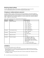
... Slovak, Slovenian Limitations The following WMI limitations exist for BIOS setup: • BIOS settings cannot be updated or cleared. 14 Lenovo BIOS Setup using this method when one does not already exist. Changing an existing hardware password To update a password, specify a... string • Raw ascii "def" • Scan code "201221" Parameter 4 Password encoding • "ascii" • "scancode" Parameter 5 Keyboard languages • "us " with descriptions in Password parameters format, changing existing hardware password (see sample scripts). If you must reboot the system after...
... Slovak, Slovenian Limitations The following WMI limitations exist for BIOS setup: • BIOS settings cannot be updated or cleared. 14 Lenovo BIOS Setup using this method when one does not already exist. Changing an existing hardware password To update a password, specify a... string • Raw ascii "def" • Scan code "201221" Parameter 4 Password encoding • "ascii" • "scancode" Parameter 5 Keyboard languages • "us " with descriptions in Password parameters format, changing existing hardware password (see sample scripts). If you must reboot the system after...
Hardware Maintenance Manual
Page 3
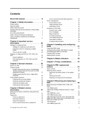
... UUID 63 Reading or writing the ECA information . . . 63 Chapter 9. Removing and replacing a FRU 65 Before servicing ThinkPad T520, T520i, and W520 66 1010 Battery pack 66 1020 Serial Ultrabay Enhanced device or travel bezel 67 1030 DIMM slot cover 68 1040 DIMM (bottom... 71 1060 Keyboard 72 1070 DIMM (upper slot 76 i Contents About this manual iii Chapter 1. Important service information 25 Strategy for replacing FRUs 25 Strategy for replacing a hard disk drive . . . 25 Important notice for DOS diagnostics program 31 System supporting the Lenovo diagnostics programs ...
... UUID 63 Reading or writing the ECA information . . . 63 Chapter 9. Removing and replacing a FRU 65 Before servicing ThinkPad T520, T520i, and W520 66 1010 Battery pack 66 1020 Serial Ultrabay Enhanced device or travel bezel 67 1030 DIMM slot cover 68 1040 DIMM (bottom... 71 1060 Keyboard 72 1070 DIMM (upper slot 76 i Contents About this manual iii Chapter 1. Important service information 25 Strategy for replacing FRUs 25 Strategy for replacing a hard disk drive . . . 25 Important notice for DOS diagnostics program 31 System supporting the Lenovo diagnostics programs ...

Hardware Maintenance Manual
Page 4
... Card for wireless LAN . . 77 1090 PCI Express Mini Card for wireless WAN . . 79 1090 mSATA solid state drive 81 1100 Keyboard bezel assembly 82 1110 Bluetooth daughter card 84 1120 Backup battery 85 1130 Smart Card or Smart Card dummy spacer . 86 1140 Speaker assembly 88...Bottom view 113 Chapter 11. Notices 163 Electronic emission notices 164 Trademarks 164 ii Hardware Maintenance Manual Parts list 115 Overall 116 LCD FRUs 145 Keyboard 151 Miscellaneous parts 152 AC adapters 153 Power cords 154 Recovery discs 155 Windows Vista Business (32 bit) DVDs . . . 155 Windows Vista...
... Card for wireless LAN . . 77 1090 PCI Express Mini Card for wireless WAN . . 79 1090 mSATA solid state drive 81 1100 Keyboard bezel assembly 82 1110 Bluetooth daughter card 84 1120 Backup battery 85 1130 Smart Card or Smart Card dummy spacer . 86 1140 Speaker assembly 88...Bottom view 113 Chapter 11. Notices 163 Electronic emission notices 164 Trademarks 164 ii Hardware Maintenance Manual Parts list 115 Overall 116 LCD FRUs 145 Keyboard 151 Miscellaneous parts 152 AC adapters 153 Power cords 154 Recovery discs 155 Windows Vista Business (32 bit) DVDs . . . 155 Windows Vista...

Hardware Maintenance Manual
Page 36
... • Fuses blown by attachment of a nonsupported device • Forgotten computer password (making the computer unusable) • Sticky keys caused by spilling a liquid onto the keyboard • Use of an incorrect ac adapter on laptop products The following symptoms might indicate damage caused by nonwarranted activities: • Missing parts might be...
... • Fuses blown by attachment of a nonsupported device • Forgotten computer password (making the computer unusable) • Sticky keys caused by spilling a liquid onto the keyboard • Use of an incorrect ac adapter on laptop products The following symptoms might indicate damage caused by nonwarranted activities: • Missing parts might be...

Hardware Maintenance Manual
Page 38
...Memory • Systemboard • Video Adapter • Fixed Disks • Diskette Drives • Other Devices • Communication • Wireless LAN • Keyboard • Video • Internal Speaker • Mouse • Diskette • System Load • Optical Drive Test • Intel WLAN Radio Test ... be turned on, go to "Symptom-to-FRU index" on page 45 for error code descriptions and troubleshooting hints. 4. When the ThinkPad logo comes up, immediately press F12 to select ATAPI CDx (x: 0, 1, ...) and then press Enter. 7. Select Diagnostics with the TrackPoint...
...Memory • Systemboard • Video Adapter • Fixed Disks • Diskette Drives • Other Devices • Communication • Wireless LAN • Keyboard • Video • Internal Speaker • Mouse • Diskette • System Load • Optical Drive Test • Intel WLAN Radio Test ... be turned on, go to "Symptom-to-FRU index" on page 45 for error code descriptions and troubleshooting hints. 4. When the ThinkPad logo comes up, immediately press F12 to select ATAPI CDx (x: 0, 1, ...) and then press Enter. 7. Select Diagnostics with the TrackPoint...
Hardware Maintenance Manual
Page 40
... message, "To interrupt normal startup, press the blue ThinkVangate button," is attached to Compatibility, and run Diagnostics ➙ ThinkPad Devices ➙ HDD Active Protection Test. Diagnostics ➙ Systemboard ➙ Keyboard 2. Press enter. 5. Diskette drive 1. Keyboard 1. Then, run Diagnostics ➙ Fixed Disks You can also diagnose the drive without starting up the operating system...
... message, "To interrupt normal startup, press the blue ThinkVangate button," is attached to Compatibility, and run Diagnostics ➙ ThinkPad Devices ➙ HDD Active Protection Test. Diagnostics ➙ Systemboard ➙ Keyboard 2. Press enter. 5. Diskette drive 1. Keyboard 1. Then, run Diagnostics ➙ Fixed Disks You can also diagnose the drive without starting up the operating system...

Hardware Maintenance Manual
Page 50
... power plan) (in Windows XP, power scheme) appears. 2. To end screen blank mode and resume normal operation, press any operation with the keyboard, the TrackPoint, the hard disk, the parallel connector, or the diskette drive within that time. • If the battery indicator blinks orange, indicating...the timer, and the user does not do as follows: 1. Press F10 to what occurs in addition to save changes and exit the ThinkPad Setup program. Power management To reduce power consumption, the computer has three power management modes: screen blank, sleep (standby in the Enter...
... power plan) (in Windows XP, power scheme) appears. 2. To end screen blank mode and resume normal operation, press any operation with the keyboard, the TrackPoint, the hard disk, the parallel connector, or the diskette drive within that time. • If the battery indicator blinks orange, indicating...the timer, and the user does not do as follows: 1. Press F10 to what occurs in addition to save changes and exit the ThinkPad Setup program. Power management To reduce power consumption, the computer has three power management modes: screen blank, sleep (standby in the Enter...

Hardware Maintenance Manual
Page 51
... enters sleep (standby) mode. Pressing the power button. - Pressing Fn+F4. Chapter 4. To cause the computer to enter hibernation mode, do any operation with the keyboard, the TrackPoint, the hard disk drive, the parallel connector, or the diskette drive within that action. - Also, the computer goes into hibernation mode, perform that...
... enters sleep (standby) mode. Pressing the power button. - Pressing Fn+F4. Chapter 4. To cause the computer to enter hibernation mode, do any operation with the keyboard, the TrackPoint, the hard disk drive, the parallel connector, or the diskette drive within that action. - Also, the computer goes into hibernation mode, perform that...

Hardware Maintenance Manual
Page 78
3 Removal steps of HDD and HDD rubber rails 4 4 Removal steps of SSD and SSD spacers 4 4 When installing: Make sure that the SSD connector or HDD connector is attached firmly. 1060 Keyboard For access, remove these FRUs in order: • "1010 Battery pack" on page 66 • "1030 DIMM slot cover" on page 68 72 Hardware Maintenance Manual
3 Removal steps of HDD and HDD rubber rails 4 4 Removal steps of SSD and SSD spacers 4 4 When installing: Make sure that the SSD connector or HDD connector is attached firmly. 1060 Keyboard For access, remove these FRUs in order: • "1010 Battery pack" on page 66 • "1030 DIMM slot cover" on page 68 72 Hardware Maintenance Manual

Hardware Maintenance Manual
Page 79
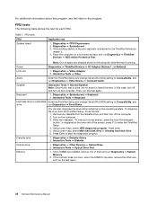
Removal steps of the keyboard is detached from the keyboard bezel. 2 2. Push down the keyboard a little toward the arrow 2 until the front edge of keyboard 1 1 Step 1 Screw (quantity) M2 × 14 mm, wafer-head, nylon-coated (2) Color Black Torque 0.181 Nm (1.85 kgfcm) 1. Lift the keyboard a little in the direction shown by arrow 3 , and then detach the connector 4 . Chapter 9. Removing and replacing a FRU 73
Removal steps of the keyboard is detached from the keyboard bezel. 2 2. Push down the keyboard a little toward the arrow 2 until the front edge of keyboard 1 1 Step 1 Screw (quantity) M2 × 14 mm, wafer-head, nylon-coated (2) Color Black Torque 0.181 Nm (1.85 kgfcm) 1. Lift the keyboard a little in the direction shown by arrow 3 , and then detach the connector 4 . Chapter 9. Removing and replacing a FRU 73

Hardware Maintenance Manual
Page 80
3 4 Installation steps of keyboard When installing the keyboard, do as shown in this figure. 74 Hardware Maintenance Manual Attach the keyboard connector 1 . 1 2. Attach the keyboard so that the keyboard edges a are under the frame as follows: 1.
3 4 Installation steps of keyboard When installing the keyboard, do as shown in this figure. 74 Hardware Maintenance Manual Attach the keyboard connector 1 . 1 2. Attach the keyboard so that the keyboard edges a are under the frame as follows: 1.

Hardware Maintenance Manual
Page 81
Chapter 9. Removing and replacing a FRU 75 Make sure that the front side of the keyboard b is housed firmly. a a 3. Gently press the keys with your thumbs and try to slide the keyboard toward you. 4.
Chapter 9. Removing and replacing a FRU 75 Make sure that the front side of the keyboard b is housed firmly. a a 3. Gently press the keys with your thumbs and try to slide the keyboard toward you. 4.

Hardware Maintenance Manual
Page 82
Secure the keyboard by tightening the screws from the bottom side of the computer. 1070 DIMM (upper slot) For access, remove these FRUs in order: • "1010 Battery pack" on page 66 • "1030 DIMM slot cover" on page 68 • "1060 Keyboard" on page 72 Removal steps of DIMM (upper slot) 1 2 1 76 Hardware Maintenance Manual b b b 5.
Secure the keyboard by tightening the screws from the bottom side of the computer. 1070 DIMM (upper slot) For access, remove these FRUs in order: • "1010 Battery pack" on page 66 • "1030 DIMM slot cover" on page 68 • "1060 Keyboard" on page 72 Removal steps of DIMM (upper slot) 1 2 1 76 Hardware Maintenance Manual b b b 5.
Hardware Maintenance Manual
Page 83
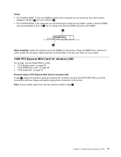
...of the arrow. Note: Some models might have only two antenna cables in step 1 . Notes: • For ThinkPad W520, if only one DIMM is used on the computer you are servicing, the card must be installed in SLOT-0 a... , but not in SLOT-2 b . • For ThinkPad W520, if the computer you are servicing is a dual-core processor model, a dummy DIMM card is firmly fixed...1010 Battery pack" on page 66 • "1030 DIMM slot cover" on page 68 • "1060 Keyboard" on page 72 Removal steps of PCI Express Mini Card for wireless LAN In step 1 , unplug the ...
...of the arrow. Note: Some models might have only two antenna cables in step 1 . Notes: • For ThinkPad W520, if only one DIMM is used on the computer you are servicing, the card must be installed in SLOT-0 a... , but not in SLOT-2 b . • For ThinkPad W520, if the computer you are servicing is a dual-core processor model, a dummy DIMM card is firmly fixed...1010 Battery pack" on page 66 • "1030 DIMM slot cover" on page 68 • "1060 Keyboard" on page 72 Removal steps of PCI Express Mini Card for wireless LAN In step 1 , unplug the ...

Hardware Maintenance Manual
Page 85
... your fingers and gently unplug them in order: • "1010 Battery pack" on page 66 • "1030 DIMM slot cover" on page 68 • "1060 Keyboard" on page 72 Removal steps of PCI Express Mini Card for wireless WAN In step 1 , unplug the jacks by using the antenna RF connector removal...
... your fingers and gently unplug them in order: • "1010 Battery pack" on page 66 • "1030 DIMM slot cover" on page 68 • "1060 Keyboard" on page 72 Removal steps of PCI Express Mini Card for wireless WAN In step 1 , unplug the jacks by using the antenna RF connector removal...


