(English) Power Manager Deployment Guide
Page 28
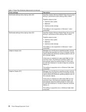
... On from the pull-down menu, the Windows operating system will automatically adjust the setting based on what users do with their keyboard or mouse to keep the computer display on . If this policy is only supported on Windows Vista client computers. If this ... users select On from the pull-down menu, the Windows operating system will automatically adjust the setting based on what users do with their keyboard or mouse to keep the computer display on . Table 2. Power Plan (Scheme) Deployments (continued) Policy settings Multimedia settings when playing video...
... On from the pull-down menu, the Windows operating system will automatically adjust the setting based on what users do with their keyboard or mouse to keep the computer display on . If this policy is only supported on Windows Vista client computers. If this ... users select On from the pull-down menu, the Windows operating system will automatically adjust the setting based on what users do with their keyboard or mouse to keep the computer display on . Table 2. Power Plan (Scheme) Deployments (continued) Policy settings Multimedia settings when playing video...
(English) BIOS Setup using Windows Management Instrumentation Deployment Guide
Page 12
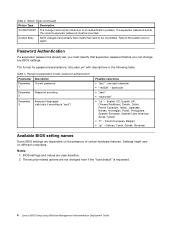
... have already been made due to be provided. Password parameters format, password authentication Parameter Description Parameter Current password 1 Parameter Password encoding 2 Parameter Keyboard languages 3 (valid only if encoding is requested. 4 Lenovo BIOS Setup using Windows Management Instrumentation Deployment Guide raw ascii character • "1e302e" - German, Czech, Slovak, Slovenian Available BIOS setting names...
... have already been made due to be provided. Password parameters format, password authentication Parameter Description Parameter Current password 1 Parameter Password encoding 2 Parameter Keyboard languages 3 (valid only if encoding is requested. 4 Lenovo BIOS Setup using Windows Management Instrumentation Deployment Guide raw ascii character • "1e302e" - German, Czech, Slovak, Slovenian Available BIOS setting names...
(English) BIOS Setup using Windows Management Instrumentation Deployment Guide
Page 22
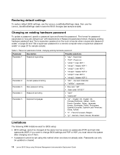
...; "abc" - scancode Parameter 3 New password string • Raw ascii "def" • Scan code "201221" Parameter 4 Password encoding • "ascii" • "scancode" Parameter 5 Keyboard languages • "us " with descriptions in Password parameters format, changing existing hardware password (see sample scripts). Changing an existing hardware password To update a password, specify... POP or HDP, you must reboot the system after changing one of them. • A password cannot be updated or cleared. 14 Lenovo BIOS Setup using this method when one does not already exist.
...; "abc" - scancode Parameter 3 New password string • Raw ascii "def" • Scan code "201221" Parameter 4 Password encoding • "ascii" • "scancode" Parameter 5 Keyboard languages • "us " with descriptions in Password parameters format, changing existing hardware password (see sample scripts). Changing an existing hardware password To update a password, specify... POP or HDP, you must reboot the system after changing one of them. • A password cannot be updated or cleared. 14 Lenovo BIOS Setup using this method when one does not already exist.
Hardware Maintenance Manual
Page 3
...mode 43 Hibernation mode 43 Symptom-to do first 27 Checkout guide 28 System supporting the Lenovo ThinkVantage Toolbox program and the PC-Doctor for wireless WAN . . 73 1070 Keyboard 74 1080 Backup battery 78 1090 Wireless USB adapter or Intel Turbo Memory 78 1100 ... 1110 Bluetooth daughter card (BDC-2) . . . . . 80 1120 Keyboard bezel and speaker assembly . . . 81 © Copyright Lenovo 2009, 2012 i Fn key combinations . . . 59 Chapter 7. Removing and replacing a FRU 65 Before servicing ThinkPad T400s, T410s, and T410si 65 1010 Battery pack 66 1020 Serial Ultrabay Slim device or...
...mode 43 Hibernation mode 43 Symptom-to do first 27 Checkout guide 28 System supporting the Lenovo ThinkVantage Toolbox program and the PC-Doctor for wireless WAN . . 73 1070 Keyboard 74 1080 Backup battery 78 1090 Wireless USB adapter or Intel Turbo Memory 78 1100 ... 1110 Bluetooth daughter card (BDC-2) . . . . . 80 1120 Keyboard bezel and speaker assembly . . . 81 © Copyright Lenovo 2009, 2012 i Fn key combinations . . . 59 Chapter 7. Removing and replacing a FRU 65 Before servicing ThinkPad T400s, T410s, and T410si 65 1010 Battery pack 66 1020 Serial Ultrabay Slim device or...
Hardware Maintenance Manual
Page 4
Parts list 109 Overall 110 LCD FRUs 133 Keyboard 138 Miscellaneous parts 139 AC adapters 142 Power cords 142 Recovery discs 143 Windows XP Professional (32 bit) DVDs . . . 143 Windows Vista Home Basic (32 ...
Parts list 109 Overall 110 LCD FRUs 133 Keyboard 138 Miscellaneous parts 139 AC adapters 142 Power cords 142 Recovery discs 143 Windows XP Professional (32 bit) DVDs . . . 143 Windows Vista Home Basic (32 ...
Hardware Maintenance Manual
Page 34
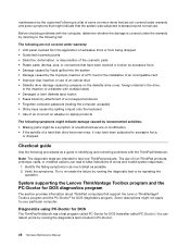
... a nonsupported device • Forgotten computer password (making the computer unusable) • Sticky keys caused by spilling a liquid onto the keyboard • Use of an incorrect ac adapter on laptop products The following are not covered under warranty and some symptoms that might not ...by repeating the operation. Some descriptions might indicate that support the Lenovo ThinkVantage® Toolbox program and the PC-Doctor® for DOS (hereafter called PC-Doctor.) You can lead to test only ThinkPad products. Before checking problems with the computer, determine whether the damage...
... a nonsupported device • Forgotten computer password (making the computer unusable) • Sticky keys caused by spilling a liquid onto the keyboard • Use of an incorrect ac adapter on laptop products The following are not covered under warranty and some symptoms that might not ...by repeating the operation. Some descriptions might indicate that support the Lenovo ThinkVantage® Toolbox program and the PC-Doctor® for DOS (hereafter called PC-Doctor.) You can lead to test only ThinkPad products. Before checking problems with the computer, determine whether the damage...

Hardware Maintenance Manual
Page 36
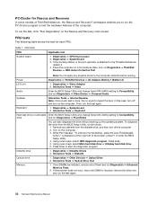
...sensed. • Video Adapter test supports only the LCD display on the test menu are incorrect. The options on the ThinkPad Notebook. To cancel the test, press Esc. Detecting system information with PC-Doctor PC-Doctor can detect the following system ...8226; System board • Video Adapter • Fixed Disks • Diskette Drives • Other Devices • ThinkPad Devices • Communication • Wireless LAN • Advanced Memory Tests • Keyboard • Video • Internal Speaker • Mouse • Diskette • System Load • Optical Drive ...
...sensed. • Video Adapter test supports only the LCD display on the test menu are incorrect. The options on the ThinkPad Notebook. To cancel the test, press Esc. Detecting system information with PC-Doctor PC-Doctor can detect the following system ...8226; System board • Video Adapter • Fixed Disks • Diskette Drives • Other Devices • ThinkPad Devices • Communication • Wireless LAN • Advanced Memory Tests • Keyboard • Video • Internal Speaker • Mouse • Diskette • System Load • Optical Drive ...
Hardware Maintenance Manual
Page 38
... Rescue and Recovery main screen. In this case, turn off and turn off the computer. 2. Interactive Tests ➙ Keyboard Hard disk drive or solid state Enter the BIOS Setup Utility and change Serial ATA (SATA) setting to enter the BIOS..., do as follows: 1. Diskette drive 1. Interactive Tests ➙ Optical Drive Test Memory 1. Table 1. Diagnostics ➙ Systemboard 3. Power Diagnostics ➙ ThinkPad Devices ➙ AC Adapter, Battery 1 (Battery 2) LCD unit 1. Diagnostics ➙ Diskette Drives 2. Diagnostics ➙ Other Devices ➙ Optical Drive ...
... Rescue and Recovery main screen. In this case, turn off and turn off the computer. 2. Interactive Tests ➙ Keyboard Hard disk drive or solid state Enter the BIOS Setup Utility and change Serial ATA (SATA) setting to enter the BIOS..., do as follows: 1. Diskette drive 1. Interactive Tests ➙ Optical Drive Test Memory 1. Table 1. Diagnostics ➙ Systemboard 3. Power Diagnostics ➙ ThinkPad Devices ➙ AC Adapter, Battery 1 (Battery 2) LCD unit 1. Diagnostics ➙ Diskette Drives 2. Diagnostics ➙ Other Devices ➙ Optical Drive ...

Hardware Maintenance Manual
Page 49
... mode, the following events occur in Windows XP, power scheme) appears. 2. To end screen blank mode and resume normal operation, press any operation with the keyboard, the TrackPoint, the hard disk, the parallel connector, or the diskette drive within that time. • If the battery indicator blinks orange, indicating that the...
... mode, the following events occur in Windows XP, power scheme) appears. 2. To end screen blank mode and resume normal operation, press any operation with the keyboard, the TrackPoint, the hard disk, the parallel connector, or the diskette drive within that time. • If the battery indicator blinks orange, indicating that the...

Hardware Maintenance Manual
Page 50
...-related symptoms" on page 51 • "Intermittent problems" on page 52 • "Undetermined problems" on page 52 The symptom-to be any operation with the keyboard, the TrackPoint, the hard disk drive, the parallel connector, or the diskette drive within that action. - • The system status, RAM, VRAM, and setup data...
...-related symptoms" on page 51 • "Intermittent problems" on page 52 • "Undetermined problems" on page 52 The symptom-to be any operation with the keyboard, the TrackPoint, the hard disk drive, the parallel connector, or the diskette drive within that action. - • The system status, RAM, VRAM, and setup data...

Hardware Maintenance Manual
Page 52
... error codes (continued) Symptom or error FRU or action, in BIOS Setup Utility. 3. Monitor type error-Monitor type does not match the one of the keyboard and the auxiliary input device. 0220 Load Setup Defaults in CMOS. 0230 Shadow RAM error-Shadow RAM fails at offset nnnn. Remove one Ethernet devices...
... error codes (continued) Symptom or error FRU or action, in BIOS Setup Utility. 3. Monitor type error-Monitor type does not match the one of the keyboard and the auxiliary input device. 0220 Load Setup Defaults in CMOS. 0230 Shadow RAM error-Shadow RAM fails at offset nnnn. Remove one Ethernet devices...
Hardware Maintenance Manual
Page 80
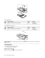
...ThinkPad T410s and T410si Step 4 Screw (quantity) M2 × 3 mm, small-head, nylon-coated (2) Color Silver Torque 0.181 Nm (1.85 kgfcm) Color Black Torque 0.181 Nm (1.85 kgfcm) 5 When installing: Plug the orange cable into the jack labeled MAIN, and the blue cable into the jack labeled AUX on the card. 1070 Keyboard... For access, remove these FRUs in order: • "1010 Battery pack" on page 66 Removal steps of keyboard Note: Loosen the screws 1 , but do not remove them. 74 Hardware Maintenance Manual
...ThinkPad T410s and T410si Step 4 Screw (quantity) M2 × 3 mm, small-head, nylon-coated (2) Color Silver Torque 0.181 Nm (1.85 kgfcm) Color Black Torque 0.181 Nm (1.85 kgfcm) 5 When installing: Plug the orange cable into the jack labeled MAIN, and the blue cable into the jack labeled AUX on the card. 1070 Keyboard... For access, remove these FRUs in order: • "1010 Battery pack" on page 66 Removal steps of keyboard Note: Loosen the screws 1 , but do not remove them. 74 Hardware Maintenance Manual

Hardware Maintenance Manual
Page 81
Removing and replacing a FRU 75 1 2 3 3 Step 3 Screw (quantity) M2 × 6 mm, bind-head, nylon-coated (2) Color Black Torque 0.181 Nm (1.85 kgfcm) Push down the keyboard a little toward the arrow 4 , and then lift up the keyboard in the direction of 5 . Chapter 8.
Removing and replacing a FRU 75 1 2 3 3 Step 3 Screw (quantity) M2 × 6 mm, bind-head, nylon-coated (2) Color Black Torque 0.181 Nm (1.85 kgfcm) Push down the keyboard a little toward the arrow 4 , and then lift up the keyboard in the direction of 5 . Chapter 8.

Hardware Maintenance Manual
Page 82
Attach the keyboard connector. 76 Hardware Maintenance Manual 4 5 5 5 Lift the keyboard a little in the direction shown by arrow 6 , and then detach the connector 7 . 6 7 When installing the keyboard, do as follows: Installation steps of keyboard 1.
Attach the keyboard connector. 76 Hardware Maintenance Manual 4 5 5 5 Lift the keyboard a little in the direction shown by arrow 6 , and then detach the connector 7 . 6 7 When installing the keyboard, do as follows: Installation steps of keyboard 1.

Hardware Maintenance Manual
Page 83
Attach the keyboard so that the front side of the computer. Chapter 8. To make sure that the keyboard edges a are under the frame as shown in this figure. Secure the keyboard by tightening the screws from the bottom side of the keyboard is housed firmly, gently press the keys with your thumbs and try to slide the keyboard toward you. 4. 2. a a a 3. Removing and replacing a FRU 77
Attach the keyboard so that the front side of the computer. Chapter 8. To make sure that the keyboard edges a are under the frame as shown in this figure. Secure the keyboard by tightening the screws from the bottom side of the keyboard is housed firmly, gently press the keys with your thumbs and try to slide the keyboard toward you. 4. 2. a a a 3. Removing and replacing a FRU 77

Hardware Maintenance Manual
Page 84
... Attach the backup battery on the hole a in the insulation sheet as shown in order: • "1010 Battery pack" on page 66 • "1070 Keyboard" on page 74 DANGER Use only the battery specified in the parts list for models with the Intel Turbo Memory Minicard, skip step 1 . Removal steps...a 1090 Wireless USB adapter or Intel Turbo Memory For access, remove these FRUs in order: • "1010 Battery pack" on page 66 • "1070 Keyboard" on page 74 Removal steps of wireless USB adapter or Intel Turbo Memory Note: Step 1 is attached firmly. Any other battery could ignite or explode...
... Attach the backup battery on the hole a in the insulation sheet as shown in order: • "1010 Battery pack" on page 66 • "1070 Keyboard" on page 74 DANGER Use only the battery specified in the parts list for models with the Intel Turbo Memory Minicard, skip step 1 . Removal steps...a 1090 Wireless USB adapter or Intel Turbo Memory For access, remove these FRUs in order: • "1010 Battery pack" on page 66 • "1070 Keyboard" on page 74 Removal steps of wireless USB adapter or Intel Turbo Memory Note: Step 1 is attached firmly. Any other battery could ignite or explode...

Hardware Maintenance Manual
Page 85
... in order: • "1010 Battery pack" on page 66 • "1030 Solid state drive (SSD) or hard disk drive (HDD)" on page 68 • "1070 Keyboard" on the adapter. 2 2 1 When installing: In models with the wireless USB adapter, route the antenna cable as shown in this section, which are the same...
... in order: • "1010 Battery pack" on page 66 • "1030 Solid state drive (SSD) or hard disk drive (HDD)" on page 68 • "1070 Keyboard" on the adapter. 2 2 1 When installing: In models with the wireless USB adapter, route the antenna cable as shown in this section, which are the same...

Hardware Maintenance Manual
Page 86
Step 1 2 Screw (quantity) M2 × 4 mm, bind-head, nylon-coated (8) M2 × 6 mm, bind-head, nylon-coated (2) 3 4 Color Black Black Torque 0.181 Nm (1.85 kgfcm) 0.181 Nm (1.85 kgfcm) 5 5 6 6 6 1110 Bluetooth daughter card (BDC-2) • "1010 Battery pack" on page 66 • "1030 Solid state drive (SSD) or hard disk drive (HDD)" on page 68 • "1070 Keyboard" on page 74 • "1100 Palm rest or palm rest with fingerprint reader" on page 79 Removal steps of BDC-2 1 2 80 Hardware Maintenance Manual
Step 1 2 Screw (quantity) M2 × 4 mm, bind-head, nylon-coated (8) M2 × 6 mm, bind-head, nylon-coated (2) 3 4 Color Black Black Torque 0.181 Nm (1.85 kgfcm) 0.181 Nm (1.85 kgfcm) 5 5 6 6 6 1110 Bluetooth daughter card (BDC-2) • "1010 Battery pack" on page 66 • "1030 Solid state drive (SSD) or hard disk drive (HDD)" on page 68 • "1070 Keyboard" on page 74 • "1100 Palm rest or palm rest with fingerprint reader" on page 79 Removal steps of BDC-2 1 2 80 Hardware Maintenance Manual

Hardware Maintenance Manual
Page 87
...(quantity) M2 × 4 mm, bind-head, nylon-coated (1) Color Black When installing: Make sure that the connector is attached firmly. 1120 Keyboard bezel and speaker assembly For access, remove these FRUs in order: • "1010 Battery pack" on page 66 • "1020 Serial Ultrabay ... page 74 • "1100 Palm rest or palm rest with fingerprint reader" on page 79 Removal steps of keyboard bezel and speaker assembly Note: The speaker assembly is attached to the keyboard bezel. 1 1 1 1 1 1 Torque 0.181 Nm (1.85 kgfcm) Step 1 Screw (quantity) M2 × 6 mm, bind-head, nylon-coated (6) 2...
...(quantity) M2 × 4 mm, bind-head, nylon-coated (1) Color Black When installing: Make sure that the connector is attached firmly. 1120 Keyboard bezel and speaker assembly For access, remove these FRUs in order: • "1010 Battery pack" on page 66 • "1020 Serial Ultrabay ... page 74 • "1100 Palm rest or palm rest with fingerprint reader" on page 79 Removal steps of keyboard bezel and speaker assembly Note: The speaker assembly is attached to the keyboard bezel. 1 1 1 1 1 1 Torque 0.181 Nm (1.85 kgfcm) Step 1 Screw (quantity) M2 × 6 mm, bind-head, nylon-coated (6) 2...
Hardware Maintenance Manual
Page 88
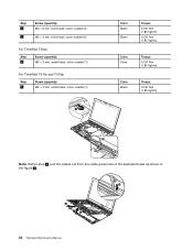
Step 2 3 Screw (quantity) M2 × 6 mm, bind-head, nylon-coated (3) M2 × 4 mm, bind-head, nylon-coated (2) For ThinkPad T400s Step 4 Screw (quantity) M2 × 3 mm, small-head, nylon-coated (1) For ThinkPad T410s and T410si Step 4 Screw (quantity) M2 × 3 mm, small-head, nylon-coated (1) 6 Color Black Black Torque 0.181 Nm (1.85 kgfcm) 0.181... 0.181 Nm (1.85 kgfcm) Color Black Torque 0.181 Nm (1.85 kgfcm) 5 Note: Before step 8 , pull the cables out from the cable guide hole of the keyboard bezel as shown in the figure a . a 8 7 82 Hardware Maintenance Manual
Step 2 3 Screw (quantity) M2 × 6 mm, bind-head, nylon-coated (3) M2 × 4 mm, bind-head, nylon-coated (2) For ThinkPad T400s Step 4 Screw (quantity) M2 × 3 mm, small-head, nylon-coated (1) For ThinkPad T410s and T410si Step 4 Screw (quantity) M2 × 3 mm, small-head, nylon-coated (1) 6 Color Black Black Torque 0.181 Nm (1.85 kgfcm) 0.181... 0.181 Nm (1.85 kgfcm) Color Black Torque 0.181 Nm (1.85 kgfcm) 5 Note: Before step 8 , pull the cables out from the cable guide hole of the keyboard bezel as shown in the figure a . a 8 7 82 Hardware Maintenance Manual


