Hardware Maintenance Manual
Page 3
... Important notice for wireless LAN . . 81 1120 Keyboard bezel assembly, FPC cable, and Bluethooth daughter card (BDC-2.1 83 1130 SmartCard or Contactless SmartCard . . . 87 1140 Modem daughter card (MDC 88 © Copyright Lenovo 2010, 2012 i FRU replacement notices 61 Screw notices...Lenovo diagnostics programs 34 Power system checkout 36 Checking the AC adapter 36 Checking operational charging 37 Checking the battery pack 37 Checking the backup battery 38 Chapter 4. Status indicators . . . . . 53 Chapter 6. Removing and replacing a FRU 65 Before servicing ThinkPad T410 and T410i...
... Important notice for wireless LAN . . 81 1120 Keyboard bezel assembly, FPC cable, and Bluethooth daughter card (BDC-2.1 83 1130 SmartCard or Contactless SmartCard . . . 87 1140 Modem daughter card (MDC 88 © Copyright Lenovo 2010, 2012 i FRU replacement notices 61 Screw notices...Lenovo diagnostics programs 34 Power system checkout 36 Checking the AC adapter 36 Checking operational charging 37 Checking the battery pack 37 Checking the backup battery 38 Chapter 4. Status indicators . . . . . 53 Chapter 6. Removing and replacing a FRU 65 Before servicing ThinkPad T410 and T410i...
Hardware Maintenance Manual
Page 39
... ➙ Video Audio Enter the BIOS Setup Utility and change Serial ATA (SATA) setting to enter the BIOS Setup Utility. 4. Remove any physical shock to the ThinkPad Notebook, detach it. 4. While the message, "To interrupt normal startup, press the blue ThinkVangate button," is displayed at the lower... test is done, the no sound is running. FRU tests The following table shows the test for each FRU. Interactive Tests ➙ Keyboard Hard disk drive or solid state Enter the BIOS Setup Utility and change Serial ATA (SATA) setting to start the diagnostic program. Interactive ...
... ➙ Video Audio Enter the BIOS Setup Utility and change Serial ATA (SATA) setting to enter the BIOS Setup Utility. 4. Remove any physical shock to the ThinkPad Notebook, detach it. 4. While the message, "To interrupt normal startup, press the blue ThinkVangate button," is displayed at the lower... test is done, the no sound is running. FRU tests The following table shows the test for each FRU. Interactive Tests ➙ Keyboard Hard disk drive or solid state Enter the BIOS Setup Utility and change Serial ATA (SATA) setting to start the diagnostic program. Interactive ...
Hardware Maintenance Manual
Page 48
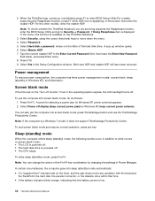
... into sleep (standby) mode automatically: • If a "suspend time" has been set on the ThinkPad Notebook. 3. Select Password. 5. Select Yes in Windows XP, keep current power scheme). To end screen... blank mode and resume normal operation, press any operation with the keyboard, the TrackPoint, the hard disk, the parallel connector, or the diskette drive within that time. ...go to move down the menu. 4. Both user HDP and master HDP will have been removed. You can change the action of the hard disk drive. Sleep (standby) mode When ...
... into sleep (standby) mode automatically: • If a "suspend time" has been set on the ThinkPad Notebook. 3. Select Password. 5. Select Yes in Windows XP, keep current power scheme). To end screen... blank mode and resume normal operation, press any operation with the keyboard, the TrackPoint, the hard disk, the parallel connector, or the diskette drive within that time. ...go to move down the menu. 4. Both user HDP and master HDP will have been removed. You can change the action of the hard disk drive. Sleep (standby) mode When ...

Hardware Maintenance Manual
Page 51
... Setup Defaults in sequence 0192 System Security- Run interactive tests of them . Remove either a Mini-PCI Card or a modem daughter card. Remove the Ethernet device that you installed; System board. 021x Keyboard error. System board. 0193 RF antenna has been removed Enter the supervisor password. 0194 The computer has been carried through a security gate...
... Setup Defaults in sequence 0192 System Security- Run interactive tests of them . Remove either a Mini-PCI Card or a modem daughter card. Remove the Ethernet device that you installed; System board. 021x Keyboard error. System board. 0193 RF antenna has been removed Enter the supervisor password. 0194 The computer has been carried through a security gate...

Hardware Maintenance Manual
Page 77
Removing and replacing a FRU 71 If you install a DIMM in only one of the two slots, install it in order: • "1010 Battery pack" on page 66 • "1050 DIMM slot cover" on page 70 Note: Your computer has two DIMM slots: one under the keyboard and another on the underside of the computer. Chapter 8. 1 2 1060 DIMM (in the slot on the underside of the computer) For access, remove these FRUs in the slot located under the keyboard.
Removing and replacing a FRU 71 If you install a DIMM in only one of the two slots, install it in order: • "1010 Battery pack" on page 66 • "1050 DIMM slot cover" on page 70 Note: Your computer has two DIMM slots: one under the keyboard and another on the underside of the computer. Chapter 8. 1 2 1060 DIMM (in the slot on the underside of the computer) For access, remove these FRUs in the slot located under the keyboard.

Hardware Maintenance Manual
Page 80
When installing: Plug the red cable into the jack labeled MAIN, and the blue cable into the jack labeled AUX on page 70 Removal steps of keyboard 1 Step 1 Screw (quantity) M2 × 10 mm, wafer-head, nylon-coated (1) 74 Hardware Maintenance Manual Color Black Torque 0.181 Nm (1.85 kgfcm) If the computer ...-ready model and does not have a wireless WAN card, route the antenna cables and secure them with a tape as shown in the following figure. 1080 Keyboard For access, remove these FRUs in order: • "1010 Battery pack" on page 66 • "1050 DIMM slot cover" on the card.
When installing: Plug the red cable into the jack labeled MAIN, and the blue cable into the jack labeled AUX on page 70 Removal steps of keyboard 1 Step 1 Screw (quantity) M2 × 10 mm, wafer-head, nylon-coated (1) 74 Hardware Maintenance Manual Color Black Torque 0.181 Nm (1.85 kgfcm) If the computer ...-ready model and does not have a wireless WAN card, route the antenna cables and secure them with a tape as shown in the following figure. 1080 Keyboard For access, remove these FRUs in order: • "1010 Battery pack" on page 66 • "1050 DIMM slot cover" on the card.

Hardware Maintenance Manual
Page 81
Removing and replacing a FRU 75 Slightly press the keyboard and slide it a little bit forward, in the direction shown by arrow 2 , to detach the front edge of the keyboard from the frame. 2 Lift the keyboard a little in the direction shown by arrow 3 , and then detach the connector 4 . 3 4 Chapter 8.
Removing and replacing a FRU 75 Slightly press the keyboard and slide it a little bit forward, in the direction shown by arrow 2 , to detach the front edge of the keyboard from the frame. 2 Lift the keyboard a little in the direction shown by arrow 3 , and then detach the connector 4 . 3 4 Chapter 8.

Hardware Maintenance Manual
Page 83
Removing and replacing a FRU 77 2. Gently press the keys with your palms and slightly slide the keyboard toward you until it snaps into position. Attach the keyboard so that the keyboard edge a is under the frame as shown in the following figure. Chapter 8. a a 3.
Removing and replacing a FRU 77 2. Gently press the keys with your palms and slightly slide the keyboard toward you until it snaps into position. Attach the keyboard so that the keyboard edge a is under the frame as shown in the following figure. Chapter 8. a a 3.

Hardware Maintenance Manual
Page 84
... tightening the screws from the bottom side of the computer. 1090 DIMM (in the slot under the keyboard) For access, remove these FRUs in the slot located under the keyboard and another on the underside of the two slots, install it in order: • "1010 Battery pack" on page 66 • "1050 DIMM... slot cover" on page 70 • "1080 Keyboard" on page 74 Note: You computer has two DIMM slots: one...
... tightening the screws from the bottom side of the computer. 1090 DIMM (in the slot under the keyboard) For access, remove these FRUs in the slot located under the keyboard and another on the underside of the two slots, install it in order: • "1010 Battery pack" on page 66 • "1050 DIMM... slot cover" on page 70 • "1080 Keyboard" on page 74 Note: You computer has two DIMM slots: one...

Hardware Maintenance Manual
Page 85
Removal steps of the DIMM into place. Chapter 8. Removing and replacing a FRU 79 Press the DIMM firmly, and pivot it until it is firmly fixed in the slot under the keyboard) 1 2 3 2 When installing: Insert the notched end of DIMM (in the slot and does not move easily. Make sure that it snaps into the socket.
Removal steps of the DIMM into place. Chapter 8. Removing and replacing a FRU 79 Press the DIMM firmly, and pivot it until it is firmly fixed in the slot under the keyboard) 1 2 3 2 When installing: Insert the notched end of DIMM (in the slot and does not move easily. Make sure that it snaps into the socket.

Hardware Maintenance Manual
Page 86
Any other battery could ignite or explode. 1 2 80 Hardware Maintenance Manual 1100 Backup battery For access, remove these FRUs in order: • "1010 Battery pack" on page 66 • "1050 DIMM slot cover" on page 70 • "1080 Keyboard" on page 74 Removal steps of backup battery DANGER Use only the battery specified in the parts list for your computer.
Any other battery could ignite or explode. 1 2 80 Hardware Maintenance Manual 1100 Backup battery For access, remove these FRUs in order: • "1010 Battery pack" on page 66 • "1050 DIMM slot cover" on page 70 • "1080 Keyboard" on page 74 Removal steps of backup battery DANGER Use only the battery specified in the parts list for your computer.

Hardware Maintenance Manual
Page 87
Removing and replacing a FRU 81 Cable routing: Attach the backup battery and route the cable as shown in the following figure and make sure that the battery connector is attached firmly. 1110 PCI Express Mini Card for wireless LAN For access, remove these FRUs in order: • "1010 Battery pack" on page 66 • "1050 DIMM slot cover" on page 70 • "1080 Keyboard" on page 74 Chapter 8.
Removing and replacing a FRU 81 Cable routing: Attach the backup battery and route the cable as shown in the following figure and make sure that the battery connector is attached firmly. 1110 PCI Express Mini Card for wireless LAN For access, remove these FRUs in order: • "1010 Battery pack" on page 66 • "1050 DIMM slot cover" on page 70 • "1080 Keyboard" on page 74 Chapter 8.
Hardware Maintenance Manual
Page 89
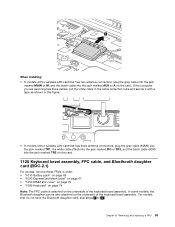
... into the jack marked MAIN or M, and the black cable into the jack marked TR2 on the card. 1120 Keyboard bezel assembly, FPC cable, and Bluethooth daughter card (BDC-2.1) For access, remove these FRUs in order: • "1010 Battery pack" on page 66 • "1020 ExpressCard blank bezel" ... page 74 Note: The FPC cable is also attached on the underside of the keyboard bezel assembly. In some models, the Bluetooth daughter card is attached on the underside of the keyboard bezel assembly. Chapter 8. Removing and replacing a FRU 83 For models that do not have the Bluetooth daughter card, ...
... into the jack marked MAIN or M, and the black cable into the jack marked TR2 on the card. 1120 Keyboard bezel assembly, FPC cable, and Bluethooth daughter card (BDC-2.1) For access, remove these FRUs in order: • "1010 Battery pack" on page 66 • "1020 ExpressCard blank bezel" ... page 74 Note: The FPC cable is also attached on the underside of the keyboard bezel assembly. In some models, the Bluetooth daughter card is attached on the underside of the keyboard bezel assembly. Chapter 8. Removing and replacing a FRU 83 For models that do not have the Bluetooth daughter card, ...

Hardware Maintenance Manual
Page 90
Removal steps of keyboard bezel assembly, FPC cable, and Bluetooth daughter card 1 1 1 2 2 2 1 1 1 Step 1 2 Screw (quantity) M2 × 14 mm, wafer-head, nylon-coated (6) M2 × 3 mm, wafer-head, nylon-coated (3) 3 3 3 3 Color Black Black Torque 0.181 Nm (1.85 kgfcm) 0.181 Nm (1.85 kgfcm) Step 3 Screw (quantity) M2 × 3 mm, wafer-head, nylon-coated (4) 84 Hardware Maintenance Manual Color Black Torque 0.181 Nm (1.85 kgfcm)
Removal steps of keyboard bezel assembly, FPC cable, and Bluetooth daughter card 1 1 1 2 2 2 1 1 1 Step 1 2 Screw (quantity) M2 × 14 mm, wafer-head, nylon-coated (6) M2 × 3 mm, wafer-head, nylon-coated (3) 3 3 3 3 Color Black Black Torque 0.181 Nm (1.85 kgfcm) 0.181 Nm (1.85 kgfcm) Step 3 Screw (quantity) M2 × 3 mm, wafer-head, nylon-coated (4) 84 Hardware Maintenance Manual Color Black Torque 0.181 Nm (1.85 kgfcm)

Hardware Maintenance Manual
Page 93
Removing and replacing a FRU 87 16 When installing: Make sure that the connector is attached firmly. 1130 SmartCard or Contactless SmartCard For access, remove these FRUs in order: • "1010 Battery pack" on page 66 • "1050 DIMM slot cover" on page 70 • "1080 Keyboard" on page 74 • "1120 Keyboard bezel assembly, FPC cable, and Bluethooth daughter card (BDC-2.1)" on page 83 Removal steps of SmartCard or Contactless SmartCard 1 1 1 1 Step 1 Screw (quantity) M2 × 3 mm, wafer-head, nylon-coated (4) Color Black Torque 0.181 Nm (1.85 kgfcm) Chapter 8.
Removing and replacing a FRU 87 16 When installing: Make sure that the connector is attached firmly. 1130 SmartCard or Contactless SmartCard For access, remove these FRUs in order: • "1010 Battery pack" on page 66 • "1050 DIMM slot cover" on page 70 • "1080 Keyboard" on page 74 • "1120 Keyboard bezel assembly, FPC cable, and Bluethooth daughter card (BDC-2.1)" on page 83 Removal steps of SmartCard or Contactless SmartCard 1 1 1 1 Step 1 Screw (quantity) M2 × 3 mm, wafer-head, nylon-coated (4) Color Black Torque 0.181 Nm (1.85 kgfcm) Chapter 8.

Hardware Maintenance Manual
Page 95
... a FRU 89 • "1050 DIMM slot cover" on page 70 • "1080 Keyboard" on page 74 • "1120 Keyboard bezel assembly, FPC cable, and Bluethooth daughter card (BDC-2.1)" on page 83 Removal steps of modem daughter card (MDC) 1 1 2 Step 1 Screw (quantity) M2 × 3 mm, wafer-head, nylon-coated ... connector is attached firmly. 1150 Speaker assembly For access, remove these FRUs in order: • "1010 Battery pack" on page 66 • "1050 DIMM slot cover" on page 70 • "1080 Keyboard" on page 74 • "1120 Keyboard bezel assembly, FPC cable, and Bluethooth daughter card (BDC...
... a FRU 89 • "1050 DIMM slot cover" on page 70 • "1080 Keyboard" on page 74 • "1120 Keyboard bezel assembly, FPC cable, and Bluethooth daughter card (BDC-2.1)" on page 83 Removal steps of modem daughter card (MDC) 1 1 2 Step 1 Screw (quantity) M2 × 3 mm, wafer-head, nylon-coated ... connector is attached firmly. 1150 Speaker assembly For access, remove these FRUs in order: • "1010 Battery pack" on page 66 • "1050 DIMM slot cover" on page 70 • "1080 Keyboard" on page 74 • "1120 Keyboard bezel assembly, FPC cable, and Bluethooth daughter card (BDC...

Hardware Maintenance Manual
Page 97
...Card for wireless WAN" on page 72 • "1080 Keyboard" on page 74 • "1110 PCI Express Mini Card for wireless LAN" on page 81 • "1120 Keyboard bezel assembly, FPC cable, and Bluethooth daughter card (BDC-2.1)" on page 83 Removal steps of LCD unit 1 1 Step 1 Screw (quantity) ...M2.5 × 6 mm, wafer-head, nylon-coated (2) Color Black Torque 0.392 Nm (4.0 kgfcm) Chapter 8. Removing and replacing a FRU 91
...Card for wireless WAN" on page 72 • "1080 Keyboard" on page 74 • "1110 PCI Express Mini Card for wireless LAN" on page 81 • "1120 Keyboard bezel assembly, FPC cable, and Bluethooth daughter card (BDC-2.1)" on page 83 Removal steps of LCD unit 1 1 Step 1 Screw (quantity) ...M2.5 × 6 mm, wafer-head, nylon-coated (2) Color Black Torque 0.392 Nm (4.0 kgfcm) Chapter 8. Removing and replacing a FRU 91

Hardware Maintenance Manual
Page 101
Removing and replacing a FRU 95 12 12 1170 Fan assembly For access, remove these FRUs in order: • "1010 Battery pack" on page 66 • "1020 ExpressCard blank bezel" on page 67 • "1050 DIMM slot cover" on page 70 • "1070 PCI Express Mini Card for wireless WAN" on page 72 • "1080 Keyboard" on page 74 • "1110 PCI Express Mini Card for wireless LAN" on page 81 • "1120 Keyboard bezel assembly, FPC cable, and Bluethooth daughter card (BDC-2.1)" on page 83 • "1150 Speaker assembly" on page 89 • "1160 LCD unit" on page 91 Chapter 8.
Removing and replacing a FRU 95 12 12 1170 Fan assembly For access, remove these FRUs in order: • "1010 Battery pack" on page 66 • "1020 ExpressCard blank bezel" on page 67 • "1050 DIMM slot cover" on page 70 • "1070 PCI Express Mini Card for wireless WAN" on page 72 • "1080 Keyboard" on page 74 • "1110 PCI Express Mini Card for wireless LAN" on page 81 • "1120 Keyboard bezel assembly, FPC cable, and Bluethooth daughter card (BDC-2.1)" on page 83 • "1150 Speaker assembly" on page 89 • "1160 LCD unit" on page 91 Chapter 8.

Hardware Maintenance Manual
Page 104
.... 1180 CPU For access, remove these FRUs in order: • "1010 Battery pack" on page 66 • "1020 ExpressCard blank bezel" on page 67 • "1050 DIMM slot cover" on page 70 • "1070 PCI Express Mini Card for wireless WAN" on page 72 • "1080 Keyboard" on page 74 •...; "1110 PCI Express Mini Card for wireless LAN" on page 81 • "1120 Keyboard bezel assembly, FPC cable, and Bluethooth daughter card (BDC-2.1)" on page 83 • "1150 Speaker assembly...
.... 1180 CPU For access, remove these FRUs in order: • "1010 Battery pack" on page 66 • "1020 ExpressCard blank bezel" on page 67 • "1050 DIMM slot cover" on page 70 • "1070 PCI Express Mini Card for wireless WAN" on page 72 • "1080 Keyboard" on page 74 •...; "1110 PCI Express Mini Card for wireless LAN" on page 81 • "1120 Keyboard bezel assembly, FPC cable, and Bluethooth daughter card (BDC-2.1)" on page 83 • "1150 Speaker assembly...

Hardware Maintenance Manual
Page 105
...on page 70 • "1070 PCI Express Mini Card for wireless WAN" on page 72 • "1080 Keyboard" on page 74 • "1110 PCI Express Mini Card for wireless LAN" on page 81 • "1120 Keyboard bezel assembly, FPC cable, and Bluethooth daughter card (BDC-2.1)" on page 83 • "1150 Speaker assembly... marked a as shown in the drawing. 1190 Base cover assembly, I/O sub card with USB connector and 1394 connector, and I/O sub card cable For access, remove these FRUs in the direction shown by arrow 3 to secure the CPU. Note: Before you install a new CPU, apply the insulation sheet on the CPU...
...on page 70 • "1070 PCI Express Mini Card for wireless WAN" on page 72 • "1080 Keyboard" on page 74 • "1110 PCI Express Mini Card for wireless LAN" on page 81 • "1120 Keyboard bezel assembly, FPC cable, and Bluethooth daughter card (BDC-2.1)" on page 83 • "1150 Speaker assembly... marked a as shown in the drawing. 1190 Base cover assembly, I/O sub card with USB connector and 1394 connector, and I/O sub card cable For access, remove these FRUs in the direction shown by arrow 3 to secure the CPU. Note: Before you install a new CPU, apply the insulation sheet on the CPU...

