Hardware Maintenance Manual
Page 38
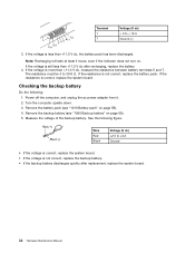
The resistance must be 4 to + 12.6 Ground (-) 3. If the resistance is not correct, replace the battery pack. Turn the computer upside down. 3. Wire Red Black Voltage (V dc) +2.5 to +3.2 Ground • If the voltage is correct, replace the system board. • If the voltage is more than +11.0 V dc after ...
The resistance must be 4 to + 12.6 Ground (-) 3. If the resistance is not correct, replace the battery pack. Turn the computer upside down. 3. Wire Red Black Voltage (V dc) +2.5 to +3.2 Ground • If the voltage is correct, replace the system board. • If the voltage is more than +11.0 V dc after ...

Hardware Maintenance Manual
Page 48
Table 5. Status indicators (continued) Indicator Meaning 3 System status 4 System status The illuminated dot in the ThinkPad logo on the outer lid of the computer and on the palm rest works as a system status indicator: it shows whether the computer is in sleep, hibernation, or normal mode. • Red: The computer is on (in normal mode). • Fast blinking red: The computer is entering sleep or hibernation mode. • Slow blinking red: The computer is in sleep mode. • Off: The computer is off or in hibernation mode. 42 Hardware Maintenance Manual
Table 5. Status indicators (continued) Indicator Meaning 3 System status 4 System status The illuminated dot in the ThinkPad logo on the outer lid of the computer and on the palm rest works as a system status indicator: it shows whether the computer is in sleep, hibernation, or normal mode. • Red: The computer is on (in normal mode). • Fast blinking red: The computer is entering sleep or hibernation mode. • Slow blinking red: The computer is in sleep mode. • Off: The computer is off or in hibernation mode. 42 Hardware Maintenance Manual

Hardware Maintenance Manual
Page 72
Step 2 Screw (quantity) M2 × 3 mm, wafer-head, nylon-coated (1) Color Black Torque 0.181 Nm (1.85 kgfcm) 3 66 Hardware Maintenance Manual • "1010 Battery pack" on page 58 • "1030 Small bottom cover" on page 60 Removal steps of PCI Express Mini Card for wireless WAN In step 1 , unplug the connectors by using the antenna RF connector removal tool or pick the connectors with your fingers and gently unplug them in the direction of the arrows. 1 2 1 When installing: Plug the red cable into the jack marked MAIN, and the blue cable into the jack marked AUX on the card.
Step 2 Screw (quantity) M2 × 3 mm, wafer-head, nylon-coated (1) Color Black Torque 0.181 Nm (1.85 kgfcm) 3 66 Hardware Maintenance Manual • "1010 Battery pack" on page 58 • "1030 Small bottom cover" on page 60 Removal steps of PCI Express Mini Card for wireless WAN In step 1 , unplug the connectors by using the antenna RF connector removal tool or pick the connectors with your fingers and gently unplug them in the direction of the arrows. 1 2 1 When installing: Plug the red cable into the jack marked MAIN, and the blue cable into the jack marked AUX on the card.

Hardware Maintenance Manual
Page 73
Step 2 Screw (quantity) M2 × 3 mm, wafer-head, nylon-coated (1) Color Black Torque 0.181 Nm (1.85 kgfcm) 3 Chapter 9. Removing or replacing a FRU 67 Removal steps of PCI Express Half Mini Card for wireless WAN In step 1 , unplug the connectors by using the antenna RF connector removal tool or pick the connectors with your fingers and gently unplug them in the direction of the arrows. 2 1 1 When installing: Plug the red cable into the jack marked MAIN, and the blue cable into the jack marked AUX on the card.
Step 2 Screw (quantity) M2 × 3 mm, wafer-head, nylon-coated (1) Color Black Torque 0.181 Nm (1.85 kgfcm) 3 Chapter 9. Removing or replacing a FRU 67 Removal steps of PCI Express Half Mini Card for wireless WAN In step 1 , unplug the connectors by using the antenna RF connector removal tool or pick the connectors with your fingers and gently unplug them in the direction of the arrows. 2 1 1 When installing: Plug the red cable into the jack marked MAIN, and the blue cable into the jack marked AUX on the card.

Hardware Maintenance Manual
Page 105
... be damaged by the cable guides, or a wire to any tension. a Wireless LAN AUX antenna (black) b Wireless WAN AUX antenna (blue) c Wireless WAN MAIN antenna (red) d Wireless LAN MAIN antenna (gray) Chapter 9. Removal steps of wireless antenna assembly and LCD rear cover assembly Release the antenna cables from the cable guides...
... be damaged by the cable guides, or a wire to any tension. a Wireless LAN AUX antenna (black) b Wireless WAN AUX antenna (blue) c Wireless WAN MAIN antenna (red) d Wireless LAN MAIN antenna (gray) Chapter 9. Removal steps of wireless antenna assembly and LCD rear cover assembly Release the antenna cables from the cable guides...

(English) User Guide
Page 27
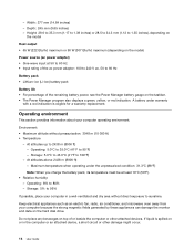
Note: Your computer keyboard might look different from the illustration above. Product overview 9 The meaning of ac power. Power status indicator Your computer has an indicator that shows the status of the indicator is as follows: • Red: The computer is on (in normal mode). • Fast blinking red: The computer is entering sleep or hibernation mode. • Slow blinking red: The computer is in sleep mode. • Off: The computer is off or in hibernation mode. Chapter 1.
Note: Your computer keyboard might look different from the illustration above. Product overview 9 The meaning of ac power. Power status indicator Your computer has an indicator that shows the status of the indicator is as follows: • Red: The computer is on (in normal mode). • Fast blinking red: The computer is entering sleep or hibernation mode. • Slow blinking red: The computer is in sleep mode. • Off: The computer is off or in hibernation mode. Chapter 1.
(English) User Guide
Page 32
...: 5.0°C to 35.0°C (41°F to 2438 m (8000 ft) - Maximum temperature when operating under warranty with a red indication is spilled on the taskbar. • The Power Manager program also displays a green, yellow, or red indication. Do not place any beverages on the hard disk drive. A battery under the unpressurized condition: 31...
...: 5.0°C to 35.0°C (41°F to 2438 m (8000 ft) - Maximum temperature when operating under warranty with a red indication is spilled on the taskbar. • The Power Manager program also displays a green, yellow, or red indication. Do not place any beverages on the hard disk drive. A battery under the unpressurized condition: 31...
(English) User Guide
Page 36
... time. Recovery Media The Recovery Media program enables you to restore the contents of the hard disk drive to access the Lenovo App Shop, from http://www.lenovo.com/support. The red launch point is not preinstalled with the Windows 7 operating system. You also can download it from which you can download various...
... time. Recovery Media The Recovery Media program enables you to restore the contents of the hard disk drive to access the Lenovo App Shop, from http://www.lenovo.com/support. The red launch point is not preinstalled with the Windows 7 operating system. You also can download it from which you can download various...


