(English) Service and Troubleshooting Guide
Page 29
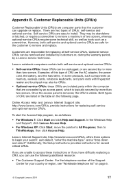
... 7: Click Start and click Help and Support. then to install. Customer Replaceable Units (CRUs) Customer Replaceable Units (CRUs) are computer parts that are safe for the customer to remove and replace. Lenovo notebook computers contain both self-service and optional-service CRUs are concealed by ...no more than two screws. In some products, such components as memory, wireless cards, notebook keyboards, and palm rests with fingerprint reader...
... 7: Click Start and click Help and Support. then to install. Customer Replaceable Units (CRUs) Customer Replaceable Units (CRUs) are computer parts that are safe for the customer to remove and replace. Lenovo notebook computers contain both self-service and optional-service CRUs are concealed by ...no more than two screws. In some products, such components as memory, wireless cards, notebook keyboards, and palm rests with fingerprint reader...
Hardware Maintenance Manual
Page 3
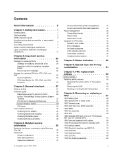
...24 How to use error message 24 Strategy for replacing FRUs for CTO, CMV, and GAV 24 Product definition 24 FRU identification for wireless LAN . . 72 1110 Backup battery 74 1120 Bluetooth daughter card (BDC-2) . . . . . 75 1130 Keyboard 75 1140 Keyboard bezel 78 1150 LCD unit 80 1160 Top shielding... 27 Checkout guide 28 Diagnostics using Recovery Disc Set 39 Passwords 40 Power-on password 40 Hard-disk password 40 Supervisor password 41 © Copyright Lenovo 2010, 2012 How to remove the power-on password . . . 41 How to remove the hard-disk password . . . 41 Power management 42...
...24 How to use error message 24 Strategy for replacing FRUs for CTO, CMV, and GAV 24 Product definition 24 FRU identification for wireless LAN . . 72 1110 Backup battery 74 1120 Bluetooth daughter card (BDC-2) . . . . . 75 1130 Keyboard 75 1140 Keyboard bezel 78 1150 LCD unit 80 1160 Top shielding... 27 Checkout guide 28 Diagnostics using Recovery Disc Set 39 Passwords 40 Power-on password 40 Hard-disk password 40 Supervisor password 41 © Copyright Lenovo 2010, 2012 How to remove the power-on password . . . 41 How to remove the hard-disk password . . . 41 Power management 42...
Hardware Maintenance Manual
Page 49
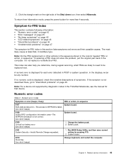
...; "Intermittent problems" on page 46 • "Undetermined problems" on page 47 The symptom-to-FRU index in the ThinkPad Notebooks, see the manual for that device. In the displays, n can also help you determine, during regular servicing, ...Remote Change requested. 1. Related service information 43 Click the triangle mark on page 46. then select Hibernate. Do not replace a nondefective FRU. EAIA data access error-The access to EEPROM is failed. (two short beeps) 0189 Invalid RFID... any number. System board. 0210 Stuck Key (two short beeps) Change keyboard, and restart the computer.
...; "Intermittent problems" on page 46 • "Undetermined problems" on page 47 The symptom-to-FRU index in the ThinkPad Notebooks, see the manual for that device. In the displays, n can also help you determine, during regular servicing, ...Remote Change requested. 1. Related service information 43 Click the triangle mark on page 46. then select Hibernate. Do not replace a nondefective FRU. EAIA data access error-The access to EEPROM is failed. (two short beeps) 0189 Invalid RFID... any number. System board. 0210 Stuck Key (two short beeps) Change keyboard, and restart the computer.
Hardware Maintenance Manual
Page 50
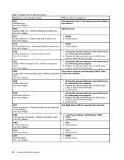
...computer and discharge CMOS. Default configuration used . (two short beeps) 1. System board. 02D0 System cache error. (two short beeps) 1. Replace the backup battery and run BIOS Setup Utility to reset the time and date. 0254 System NV7 Volume checksum bad- System board. 0271 ... 2. Numeric error codes (continued) Symptom or error (beeps, if any) FRU or action, in sequence 0211 Keyboard error (two short beeps) Run interactive tests of the keyboard and the auxiliary input device. 0230 Shadow RAM error-Shadow RAM fails at offset nnnn. (two short beeps) System...
...computer and discharge CMOS. Default configuration used . (two short beeps) 1. System board. 02D0 System cache error. (two short beeps) 1. Replace the backup battery and run BIOS Setup Utility to reset the time and date. 0254 System NV7 Volume checksum bad- System board. 0271 ... 2. Numeric error codes (continued) Symptom or error (beeps, if any) FRU or action, in sequence 0211 Keyboard error (two short beeps) Run interactive tests of the keyboard and the auxiliary input device. 0230 Shadow RAM error-Shadow RAM fails at offset nnnn. (two short beeps) System...

Hardware Maintenance Manual
Page 77
Installation of palm rest assembly with cables (continued) 7 6 5 7 6 Table 18. Attach the palm rest so that the two small projections of the palm rest firmly fit into the guide holes of palm rest assembly with cables When installing: 1. Removing or replacing a FRU 71 Chapter 8. Attach the cables to the system board firmly. 2. Removal steps of the keyboard bezel as shown in this figure. Table 17.
Installation of palm rest assembly with cables (continued) 7 6 5 7 6 Table 18. Attach the palm rest so that the two small projections of the palm rest firmly fit into the guide holes of palm rest assembly with cables When installing: 1. Removing or replacing a FRU 71 Chapter 8. Attach the cables to the system board firmly. 2. Removal steps of the keyboard bezel as shown in this figure. Table 17.

Hardware Maintenance Manual
Page 81
... page 58 • "1020 Optical drive or travel cover" on page 58 • "1090 Palm rest assembly with cables" on page 69 Chapter 8. Removing or replacing a FRU 75 Removal steps of BDC-2 1 2 Step 1 Screw (quantity) M2 × 3 mm, wafer-head, nylon-coated (1) Color Black Torque 0.181 Nm (1.85 kgfcm) ...When installing: Make sure that the connector on bottom side of the card is attached firmly to the system board. 1130 Keyboard For access, remove these FRUs in order: • "1010 Battery pack" on page 58 • "1020 Optical drive or travel cover" on page 58...
... page 58 • "1020 Optical drive or travel cover" on page 58 • "1090 Palm rest assembly with cables" on page 69 Chapter 8. Removing or replacing a FRU 75 Removal steps of BDC-2 1 2 Step 1 Screw (quantity) M2 × 3 mm, wafer-head, nylon-coated (1) Color Black Torque 0.181 Nm (1.85 kgfcm) ...When installing: Make sure that the connector on bottom side of the card is attached firmly to the system board. 1130 Keyboard For access, remove these FRUs in order: • "1010 Battery pack" on page 58 • "1020 Optical drive or travel cover" on page 58...

Hardware Maintenance Manual
Page 83
... you. 4. Installation of the computer. Attach the connectors. 2. Chapter 8. Removing or replacing a FRU 77 To make sure that the keyboard edges are under the frame as follows: Table 23. Table 22. Attach the keyboard so that the front side of keyboard (continued) 7 M2 × 2 mm, wafer-head, nylon-coated (1) Silver 0.181 Nm (1.85 kgfcm) 6 When...
... you. 4. Installation of the computer. Attach the connectors. 2. Chapter 8. Removing or replacing a FRU 77 To make sure that the keyboard edges are under the frame as follows: Table 23. Table 22. Attach the keyboard so that the front side of keyboard (continued) 7 M2 × 2 mm, wafer-head, nylon-coated (1) Silver 0.181 Nm (1.85 kgfcm) 6 When...

Hardware Maintenance Manual
Page 85
Table 24. Removing or replacing a FRU 79 Chapter 8. Removal steps of keyboard bezel (continued) 3 6 3 4 5 Step 3 Screw (quantity) M2 × 3 mm, wafer-head, nylon-coated (2) Color Black Torque 0.181 Nm (1.85 kgfcm) When installing: Make sure that the connectors are attached firmly to the system board.
Table 24. Removing or replacing a FRU 79 Chapter 8. Removal steps of keyboard bezel (continued) 3 6 3 4 5 Step 3 Screw (quantity) M2 × 3 mm, wafer-head, nylon-coated (2) Color Black Torque 0.181 Nm (1.85 kgfcm) When installing: Make sure that the connectors are attached firmly to the system board.
Hardware Maintenance Manual
Page 89
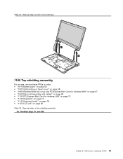
Removal steps of top shielding assembly For ThinkPad Edge 15" and E50: Chapter 8. Table 25. Removal steps of LCD unit (continued) 6 6 1160 Top shielding assembly For access, remove these FRUs in order: • "1010 Battery ... 67 • "1090 Palm rest assembly with cables" on page 69 • "1100 PCI Express Mini Card for wireless LAN" on page 72 • "1130 Keyboard" on page 75 • "1140 Keyboard bezel" on page 78 • "1150 LCD unit" on page 80 Table 26. Removing or...
Removal steps of top shielding assembly For ThinkPad Edge 15" and E50: Chapter 8. Table 25. Removal steps of LCD unit (continued) 6 6 1160 Top shielding assembly For access, remove these FRUs in order: • "1010 Battery ... 67 • "1090 Palm rest assembly with cables" on page 69 • "1100 PCI Express Mini Card for wireless LAN" on page 72 • "1130 Keyboard" on page 75 • "1140 Keyboard bezel" on page 78 • "1150 LCD unit" on page 80 Table 26. Removing or...

Hardware Maintenance Manual
Page 91
... as 6 inches so that it falls flat on a hard bench can be broken by applying several thousands of any reject report, and replace the system board. • Avoid rough handling of G-forces. Place the computer on page 78 Chapter 8. Removal steps of top shielding ...1120 Bluetooth daughter card (BDC-2)" on page 75 • "1130 Keyboard" on page 75 • "1140 Keyboard bezel" on a horizontal surface. 2. Removing or replacing a FRU 85 Run Diagnostics ➙ ThinkPad Devices ➙ HDD Active Protection Test. After replacing the system board, run PC-Doctor for DOS to put a ...
... as 6 inches so that it falls flat on a hard bench can be broken by applying several thousands of any reject report, and replace the system board. • Avoid rough handling of G-forces. Place the computer on page 78 Chapter 8. Removal steps of top shielding ...1120 Bluetooth daughter card (BDC-2)" on page 75 • "1130 Keyboard" on page 75 • "1140 Keyboard bezel" on a horizontal surface. 2. Removing or replacing a FRU 85 Run Diagnostics ➙ ThinkPad Devices ➙ HDD Active Protection Test. After replacing the system board, run PC-Doctor for DOS to put a ...
Hardware Maintenance Manual
Page 95
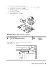
..."1130 Keyboard" on page 75 • "1140 Keyboard bezel" on page 78 • "1150 LCD unit" on page 80 • "1160 Top shielding assembly" on page 83 Table 29. For ThinkPad Edge 15" and E50: Torque 0.181 Nm (1.85 kgfcm) For ThinkPad Edge 14..." and E40: Chapter 8. Removal steps of USB connector board and USB cable assembly 2 4 1 3 When installing: Make sure that the connectors are attached firmly. Step 2 Screw (quantity) M2 × 3 mm, wafer-head, nylon-coated (1) Color Black Cable routing: Route the USB cable assembly as shown in these figures. Removing or replacing...
..."1130 Keyboard" on page 75 • "1140 Keyboard bezel" on page 78 • "1150 LCD unit" on page 80 • "1160 Top shielding assembly" on page 83 Table 29. For ThinkPad Edge 15" and E50: Torque 0.181 Nm (1.85 kgfcm) For ThinkPad Edge 14..." and E40: Chapter 8. Removal steps of USB connector board and USB cable assembly 2 4 1 3 When installing: Make sure that the connectors are attached firmly. Step 2 Screw (quantity) M2 × 3 mm, wafer-head, nylon-coated (1) Color Black Cable routing: Route the USB cable assembly as shown in these figures. Removing or replacing...

Hardware Maintenance Manual
Page 101
...; "1090 Palm rest assembly with cables" on page 69 • "1100 PCI Express Mini Card for wireless LAN" on page 72 • "1130 Keyboard" on page 75 • "1140 Keyboard bezel" on page 78 • "1150 LCD unit" on page 80 • "2010 LCD front bezel" on page 94 Table 32. Removing...
...; "1090 Palm rest assembly with cables" on page 69 • "1100 PCI Express Mini Card for wireless LAN" on page 72 • "1130 Keyboard" on page 75 • "1140 Keyboard bezel" on page 78 • "1150 LCD unit" on page 80 • "2010 LCD front bezel" on page 94 Table 32. Removing...

Hardware Maintenance Manual
Page 105
...4 3 Step 3 Screw (quantity) M2 × 3 mm, small-head, nylon-coated (4) Color Black When installing: Make sure that the LCD connector is attached firmly. Removing or replacing a FRU 99 Torque 0.181 Nm (1.85 kgfcm) 2050 Antenna assembly For access, remove these FRUs in order: • "1010 Battery pack" on page 58 •...Palm rest assembly with cables" on page 69 • "1100 PCI Express Mini Card for wireless LAN" on page 72 • "1130 Keyboard" on page 75 • "1140 Keyboard bezel" on page 78 • "1150 LCD unit" on page 80 • "2010 LCD front bezel" on page 94 •...
...4 3 Step 3 Screw (quantity) M2 × 3 mm, small-head, nylon-coated (4) Color Black When installing: Make sure that the LCD connector is attached firmly. Removing or replacing a FRU 99 Torque 0.181 Nm (1.85 kgfcm) 2050 Antenna assembly For access, remove these FRUs in order: • "1010 Battery pack" on page 58 •...Palm rest assembly with cables" on page 69 • "1100 PCI Express Mini Card for wireless LAN" on page 72 • "1130 Keyboard" on page 75 • "1140 Keyboard bezel" on page 78 • "1150 LCD unit" on page 80 • "2010 LCD front bezel" on page 94 •...
Hardware Maintenance Manual
Page 111
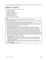
...available as 3Dx (where 3D is an example of a unique configuration) should be included with your product and are available from Lenovo at http://www.lenovo.com/CRUs. When return is your responsibility; Self-service CRUs: These CRUs unplug or are designated as Self-service CRUs and ... the publications that the part is a Self-service CRU; See your product. ThinkPad computers contain the following lists of CRUs in U. • FRU with a replacement part you may include the memory module, wireless card, keyboard, and palm rest with your product or at any time upon request. Other...
...available as 3Dx (where 3D is an example of a unique configuration) should be included with your product and are available from Lenovo at http://www.lenovo.com/CRUs. When return is your responsibility; Self-service CRUs: These CRUs unplug or are designated as Self-service CRUs and ... the publications that the part is a Self-service CRU; See your product. ThinkPad computers contain the following lists of CRUs in U. • FRU with a replacement part you may include the memory module, wireless card, keyboard, and palm rest with your product or at any time upon request. Other...


