Hardware Maintenance Manual
Page 3
... using Recovery Disc Set 39 Passwords 40 Power-on password 40 Hard-disk password 40 Supervisor password 41 © Copyright Lenovo 2010, 2012 How to remove the power-on password . . . 41 How to remove the hard-disk password . . . 41 Power management 42 Screen blank mode 42 Sleep mode 42 Hibernation mode 42 Symptom... rest assembly with cables 69 1100 PCI Express Mini Card for wireless LAN . . 72 1110 Backup battery 74 1120 Bluetooth daughter card (BDC-2) . . . . . 75 1130 Keyboard 75 1140 Keyboard bezel 78 1150 LCD unit 80 1160 Top shielding assembly 83 i
... using Recovery Disc Set 39 Passwords 40 Power-on password 40 Hard-disk password 40 Supervisor password 41 © Copyright Lenovo 2010, 2012 How to remove the power-on password . . . 41 How to remove the hard-disk password . . . 41 Power management 42 Screen blank mode 42 Sleep mode 42 Hibernation mode 42 Symptom... rest assembly with cables 69 1100 PCI Express Mini Card for wireless LAN . . 72 1110 Backup battery 74 1120 Bluetooth daughter card (BDC-2) . . . . . 75 1130 Keyboard 75 1140 Keyboard bezel 78 1150 LCD unit 80 1160 Top shielding assembly 83 i
Hardware Maintenance Manual
Page 40
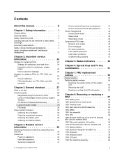
... Systemboard Diagnostics ➙ ThinkPad Devices ➙ AC Adapter ➙ Battery 1 (Battery2) 1. Diagnostics ➙ Video Adapter 2. Interactive Tests ➙ Internal Speaker Note: Once Audio test is done, the no service action is necessary. Diagnostics ➙ Systemboard ➙ Keyboard 2. Remove any diskette from the... BIOS Setup Utility, do as follows: 1. If two DIMMs are installed, remove one , and run the test again. FRU tests FRU System board...
... Systemboard Diagnostics ➙ ThinkPad Devices ➙ AC Adapter ➙ Battery 1 (Battery2) 1. Diagnostics ➙ Video Adapter 2. Interactive Tests ➙ Internal Speaker Note: Once Audio test is done, the no service action is necessary. Diagnostics ➙ Systemboard ➙ Keyboard 2. Remove any diskette from the... BIOS Setup Utility, do as follows: 1. If two DIMMs are installed, remove one , and run the test again. FRU tests FRU System board...

Hardware Maintenance Manual
Page 77
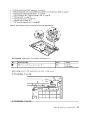
Removal steps of palm rest assembly with cables When installing: 1. Attach the palm rest so that the two small projections of the palm rest firmly fit into the guide holes of palm rest assembly with cables (continued) 7 6 5 7 6 Table 18. Removing or replacing a FRU 71 Table 17. Installation of the keyboard bezel as shown in this figure. Attach the cables to the system board firmly. 2. Chapter 8.
Removal steps of palm rest assembly with cables When installing: 1. Attach the palm rest so that the two small projections of the palm rest firmly fit into the guide holes of palm rest assembly with cables (continued) 7 6 5 7 6 Table 18. Removing or replacing a FRU 71 Table 17. Installation of the keyboard bezel as shown in this figure. Attach the cables to the system board firmly. 2. Chapter 8.

Hardware Maintenance Manual
Page 81
... Nm (1.85 kgfcm) When installing: Make sure that the connector on bottom side of the card is attached firmly to the system board. 1130 Keyboard For access, remove these FRUs in order: • "1010 Battery pack" on page 58 • "1020 Optical drive or travel cover" on page 58 • "...1090 Palm rest assembly with cables" on page 69 Table 21. Removing or replacing a FRU 75 1120 Bluetooth daughter card (BDC-2) For access, remove these FRUs in order: • "1010 Battery pack" on page 58 • "1020 Optical drive or travel cover"...
... Nm (1.85 kgfcm) When installing: Make sure that the connector on bottom side of the card is attached firmly to the system board. 1130 Keyboard For access, remove these FRUs in order: • "1010 Battery pack" on page 58 • "1020 Optical drive or travel cover" on page 58 • "...1090 Palm rest assembly with cables" on page 69 Table 21. Removing or replacing a FRU 75 1120 Bluetooth daughter card (BDC-2) For access, remove these FRUs in order: • "1010 Battery pack" on page 58 • "1020 Optical drive or travel cover"...

Hardware Maintenance Manual
Page 82
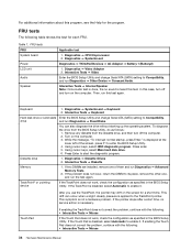
Removal steps of keyboard 1 1 Step 1 Screw (quantity) M2 × 5 mm, wafer-head, nylon-coated (1) Color Black Torque 0.181 Nm (1.85 kgfcm) 2 3 2 4 5 Step 6 Screw (quantity) M2 × 3 mm, wafer-head, nylon-coated (1) 76 Hardware Maintenance Manual Color Black Torque 0.181 Nm (1.85 kgfcm) Table 22.
Removal steps of keyboard 1 1 Step 1 Screw (quantity) M2 × 5 mm, wafer-head, nylon-coated (1) Color Black Torque 0.181 Nm (1.85 kgfcm) 2 3 2 4 5 Step 6 Screw (quantity) M2 × 3 mm, wafer-head, nylon-coated (1) 76 Hardware Maintenance Manual Color Black Torque 0.181 Nm (1.85 kgfcm) Table 22.

Hardware Maintenance Manual
Page 83
... housed firmly, gently press the keys with your thumbs and try to slide the keyboard toward you. 4. Chapter 8. Removal steps of the keyboard 1. To make sure that the keyboard edges are under the frame as follows: Table 23. Table 22. Installation of keyboard (continued) 7 M2 × 2 mm, wafer-head, nylon-coated (1) Silver 0.181 Nm (1.85 kgfcm...
... housed firmly, gently press the keys with your thumbs and try to slide the keyboard toward you. 4. Chapter 8. Removal steps of the keyboard 1. To make sure that the keyboard edges are under the frame as follows: Table 23. Table 22. Installation of keyboard (continued) 7 M2 × 2 mm, wafer-head, nylon-coated (1) Silver 0.181 Nm (1.85 kgfcm...

Hardware Maintenance Manual
Page 84
Removal steps of keyboard bezel 1 2 2 2 2 2 1 Step 1 2 Screw (quantity) M2.5 × 6.5 mm, wafer-head, nylon-coated (2) M2 × 3 mm, wafer-head, nylon-coated (5) Color Black Black Torque 0.392 Nm (4 kgfcm) 0.181 Nm (1.85 kgfcm) 78 Hardware Maintenance Manual 1140 Keyboard bezel For access, remove these FRUs in order: • "1010 Battery pack" on page 58 • "1020 Optical drive or travel cover" on page 58 • "1090 Palm rest assembly with cables" on page 69 • "1130 Keyboard" on page 75 Table 24.
Removal steps of keyboard bezel 1 2 2 2 2 2 1 Step 1 2 Screw (quantity) M2.5 × 6.5 mm, wafer-head, nylon-coated (2) M2 × 3 mm, wafer-head, nylon-coated (5) Color Black Black Torque 0.392 Nm (4 kgfcm) 0.181 Nm (1.85 kgfcm) 78 Hardware Maintenance Manual 1140 Keyboard bezel For access, remove these FRUs in order: • "1010 Battery pack" on page 58 • "1020 Optical drive or travel cover" on page 58 • "1090 Palm rest assembly with cables" on page 69 • "1130 Keyboard" on page 75 Table 24.

Hardware Maintenance Manual
Page 85
Removing or replacing a FRU 79 Table 24. Removal steps of keyboard bezel (continued) 3 6 3 4 5 Step 3 Screw (quantity) M2 × 3 mm, wafer-head, nylon-coated (2) Color Black Torque 0.181 Nm (1.85 kgfcm) When installing: Make sure that the connectors are attached firmly to the system board. Chapter 8.
Removing or replacing a FRU 79 Table 24. Removal steps of keyboard bezel (continued) 3 6 3 4 5 Step 3 Screw (quantity) M2 × 3 mm, wafer-head, nylon-coated (2) Color Black Torque 0.181 Nm (1.85 kgfcm) When installing: Make sure that the connectors are attached firmly to the system board. Chapter 8.

Hardware Maintenance Manual
Page 86
... LCD unit Step Screw (quantity) 80 Hardware Maintenance Manual 1 1 Color Torque Table 24. Removal steps of keyboard bezel (continued) 8 8 7 1150 LCD unit For access, remove these FRUs in order: • "1010 Battery pack" on page 58 • "1020 Optical drive or travel cover" on page 58 • "1080 Wireless WAN ... 67 • "1090 Palm rest assembly with cables" on page 69 • "1100 PCI Express Mini Card for wireless LAN" on page 72 • "1130 Keyboard" on page 75 • "1140 Keyboard bezel" on page 78 Table 25.
... LCD unit Step Screw (quantity) 80 Hardware Maintenance Manual 1 1 Color Torque Table 24. Removal steps of keyboard bezel (continued) 8 8 7 1150 LCD unit For access, remove these FRUs in order: • "1010 Battery pack" on page 58 • "1020 Optical drive or travel cover" on page 58 • "1080 Wireless WAN ... 67 • "1090 Palm rest assembly with cables" on page 69 • "1100 PCI Express Mini Card for wireless LAN" on page 72 • "1130 Keyboard" on page 75 • "1140 Keyboard bezel" on page 78 Table 25.
Hardware Maintenance Manual
Page 89
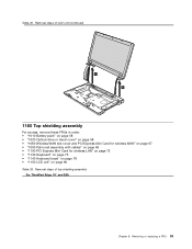
... a FRU 83 Table 25. Removal steps of top shielding assembly For ThinkPad Edge 15" and E50: Chapter 8. Removal steps of LCD unit (continued) 6 6 1160 Top shielding assembly For access, remove these FRUs in order: • "1010 Battery pack" on page 58 • "1020 Optical drive or travel cover" on page 58 • "1080 Wireless WAN... 67 • "1090 Palm rest assembly with cables" on page 69 • "1100 PCI Express Mini Card for wireless LAN" on page 72 • "1130 Keyboard" on page 75 • "1140 Keyboard bezel" on page 78 • "1150 LCD unit" on page 80 Table 26.
... a FRU 83 Table 25. Removal steps of top shielding assembly For ThinkPad Edge 15" and E50: Chapter 8. Removal steps of LCD unit (continued) 6 6 1160 Top shielding assembly For access, remove these FRUs in order: • "1010 Battery pack" on page 58 • "1020 Optical drive or travel cover" on page 58 • "1080 Wireless WAN... 67 • "1090 Palm rest assembly with cables" on page 69 • "1100 PCI Express Mini Card for wireless LAN" on page 72 • "1130 Keyboard" on page 75 • "1140 Keyboard bezel" on page 78 • "1150 LCD unit" on page 80 Table 26.

Hardware Maintenance Manual
Page 91
...you put it only on a padded surface such as an ESD mat or conductive corrugated material. For access, remove these FRUs, in mind. • The system board has an accelerometer, which can subject the accelerometer to as... much as 6,000 G's of G-forces. Run Diagnostics ➙ ThinkPad Devices ➙ HDD Active Protection Test. Note: Dropping a system board from a height of as little as 6... Bluetooth daughter card (BDC-2)" on page 75 • "1130 Keyboard" on page 75 • "1140 Keyboard bezel" on a horizontal surface. 2.
...you put it only on a padded surface such as an ESD mat or conductive corrugated material. For access, remove these FRUs, in mind. • The system board has an accelerometer, which can subject the accelerometer to as... much as 6,000 G's of G-forces. Run Diagnostics ➙ ThinkPad Devices ➙ HDD Active Protection Test. Note: Dropping a system board from a height of as little as 6... Bluetooth daughter card (BDC-2)" on page 75 • "1130 Keyboard" on page 75 • "1140 Keyboard bezel" on a horizontal surface. 2.
Hardware Maintenance Manual
Page 95
...wafer-head, nylon-coated (1) Color Black Cable routing: Route the USB cable assembly as shown in these figures. Removing or replacing a FRU 89 For ThinkPad Edge 15" and E50: Torque 0.181 Nm (1.85 kgfcm) For ThinkPad Edge 14" and E40: Chapter 8. • "1040 Hard disk drive (HDD) assembly" on page 60 • ...Palm rest assembly with cables" on page 69 • "1100 PCI Express Mini Card for wireless LAN" on page 72 • "1130 Keyboard" on page 75 • "1140 Keyboard bezel" on page 78 • "1150 LCD unit" on page 80 • "1160 Top shielding assembly" on page 83 Table 29...
...wafer-head, nylon-coated (1) Color Black Cable routing: Route the USB cable assembly as shown in these figures. Removing or replacing a FRU 89 For ThinkPad Edge 15" and E50: Torque 0.181 Nm (1.85 kgfcm) For ThinkPad Edge 14" and E40: Chapter 8. • "1040 Hard disk drive (HDD) assembly" on page 60 • ...Palm rest assembly with cables" on page 69 • "1100 PCI Express Mini Card for wireless LAN" on page 72 • "1130 Keyboard" on page 75 • "1140 Keyboard bezel" on page 78 • "1150 LCD unit" on page 80 • "1160 Top shielding assembly" on page 83 Table 29...
Hardware Maintenance Manual
Page 96
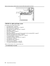
... USB connector board and USB cable assembly (continued) 1190 DC-in cable and base cover For access, remove these FRUs in cable and base cover For ThinkPad Edge 15" and E50: 90 Hardware Maintenance Manual Removal steps of DC-in order: • "1010 Battery pack" on page 58 • "1020 Optical drive ..." on page 72 • "1110 Backup battery" on page 74 • "1120 Bluetooth daughter card (BDC-2)" on page 75 • "1130 Keyboard" on page 75 • "1140 Keyboard bezel" on page 78 • "1150 LCD unit" on page 80 • "1160 Top shielding assembly" on page 83 • "1170 System...
... USB connector board and USB cable assembly (continued) 1190 DC-in cable and base cover For access, remove these FRUs in cable and base cover For ThinkPad Edge 15" and E50: 90 Hardware Maintenance Manual Removal steps of DC-in order: • "1010 Battery pack" on page 58 • "1020 Optical drive ..." on page 72 • "1110 Backup battery" on page 74 • "1120 Bluetooth daughter card (BDC-2)" on page 75 • "1130 Keyboard" on page 75 • "1140 Keyboard bezel" on page 78 • "1150 LCD unit" on page 80 • "1160 Top shielding assembly" on page 83 • "1170 System...

Hardware Maintenance Manual
Page 100
...) M2 × 5 mm, wafer-head, nylon-coated (4) Color Black 94 Hardware Maintenance Manual Torque 0.181 Nm (1.85 kgfcm) For ThinkPad Edge 14" and E40: 1 2 3 4 12 5 11 6 7 10 9 8 2010 LCD front bezel For access, remove these FRUs in order: • "1010 Battery pack" on page 58 • "1080 Wireless WAN slot cover and PCI Express... 67 • "1090 Palm rest assembly with cables" on page 69 • "1100 PCI Express Mini Card for wireless LAN" on page 72 • "1130 Keyboard" on page 75 • "1140 Keyboard bezel" on page 78 • "1150 LCD unit" on page 80 Table 31.
...) M2 × 5 mm, wafer-head, nylon-coated (4) Color Black 94 Hardware Maintenance Manual Torque 0.181 Nm (1.85 kgfcm) For ThinkPad Edge 14" and E40: 1 2 3 4 12 5 11 6 7 10 9 8 2010 LCD front bezel For access, remove these FRUs in order: • "1010 Battery pack" on page 58 • "1080 Wireless WAN slot cover and PCI Express... 67 • "1090 Palm rest assembly with cables" on page 69 • "1100 PCI Express Mini Card for wireless LAN" on page 72 • "1130 Keyboard" on page 75 • "1140 Keyboard bezel" on page 78 • "1150 LCD unit" on page 80 Table 31.

Hardware Maintenance Manual
Page 101
...(continued) 22 2 2 2 2 2 22 When installing: Make sure that all the latches are attached firmly. Removing or replacing a FRU 95 Table 31. Then secure the bezel with the screws. 2020 Speaker assembly For access, remove these FRUs in order: • "1010 Battery pack" on page 58 • "1080 Wireless WAN slot... "1090 Palm rest assembly with cables" on page 69 • "1100 PCI Express Mini Card for wireless LAN" on page 72 • "1130 Keyboard" on page 75 • "1140 Keyboard bezel" on page 78 • "1150 LCD unit" on page 80 • "2010 LCD front bezel" on page 94 Table 32.
...(continued) 22 2 2 2 2 2 22 When installing: Make sure that all the latches are attached firmly. Removing or replacing a FRU 95 Table 31. Then secure the bezel with the screws. 2020 Speaker assembly For access, remove these FRUs in order: • "1010 Battery pack" on page 58 • "1080 Wireless WAN slot... "1090 Palm rest assembly with cables" on page 69 • "1100 PCI Express Mini Card for wireless LAN" on page 72 • "1130 Keyboard" on page 75 • "1140 Keyboard bezel" on page 78 • "1150 LCD unit" on page 80 • "2010 LCD front bezel" on page 94 Table 32.
Hardware Maintenance Manual
Page 102
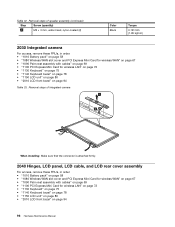
... Step Screw (quantity) 1 M2 × 3 mm, wafer-head, nylon-coated (2) Color Black Torque 0.181 Nm (1.85 kgfcm) 2030 Integrated camera For access, remove these FRUs, in order: • "1010 Battery pack" on page 58 • "1080 Wireless WAN slot cover and PCI Express Mini Card for wireless WAN... page 75 • "1140 Keyboard bezel" on page 78 • "1150 LCD unit" on page 80 • "2010 LCD front bezel" on page 94 96 Hardware Maintenance Manual Removal steps of integrated camera 1 2 When installing: Make sure that the connector is attached firmly. 2040 Hinges, LCD panel, LCD ...
... Step Screw (quantity) 1 M2 × 3 mm, wafer-head, nylon-coated (2) Color Black Torque 0.181 Nm (1.85 kgfcm) 2030 Integrated camera For access, remove these FRUs, in order: • "1010 Battery pack" on page 58 • "1080 Wireless WAN slot cover and PCI Express Mini Card for wireless WAN... page 75 • "1140 Keyboard bezel" on page 78 • "1150 LCD unit" on page 80 • "2010 LCD front bezel" on page 94 96 Hardware Maintenance Manual Removal steps of integrated camera 1 2 When installing: Make sure that the connector is attached firmly. 2040 Hinges, LCD panel, LCD ...

Hardware Maintenance Manual
Page 105
...Color Black When installing: Make sure that the LCD connector is attached firmly. Table 34. Torque 0.181 Nm (1.85 kgfcm) 2050 Antenna assembly For access, remove these FRUs in order: • "1010 Battery pack" on page 58 • "1080 Wireless WAN slot cover and PCI Express Mini Card for wireless...Keyboard bezel" on page 78 • "1150 LCD unit" on page 80 • "2010 LCD front bezel" on page 94 • "2020 Speaker assembly" on page 95 • "2030 Integrated camera" on page 96 • "2040 Hinges, LCD panel, LCD cable, and LCD rear cover assembly" on page 96 Chapter 8. Removing...
...Color Black When installing: Make sure that the LCD connector is attached firmly. Table 34. Torque 0.181 Nm (1.85 kgfcm) 2050 Antenna assembly For access, remove these FRUs in order: • "1010 Battery pack" on page 58 • "1080 Wireless WAN slot cover and PCI Express Mini Card for wireless...Keyboard bezel" on page 78 • "1150 LCD unit" on page 80 • "2010 LCD front bezel" on page 94 • "2020 Speaker assembly" on page 95 • "2030 Integrated camera" on page 96 • "2040 Hinges, LCD panel, LCD cable, and LCD rear cover assembly" on page 96 Chapter 8. Removing...
Hardware Maintenance Manual
Page 111
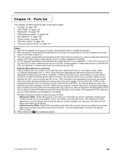
...the access panel is removed, the specific CRU is visible. • FRUs marked with specific models listed and described as 3Dx (where 3D is your Lenovo Limited Warranty documentation for ...) is not a CRU. two asterisks (**) means that is typically secured by the CRU. ThinkPad computers contain the following lists of Self-service CRUs is an example of CRUs include the ac... product design may include the memory module, wireless card, keyboard, and palm rest with the replacement CRU; You may request that Lenovo installs an Optional-service CRU according to return the defective ...
...the access panel is removed, the specific CRU is visible. • FRUs marked with specific models listed and described as 3Dx (where 3D is your Lenovo Limited Warranty documentation for ...) is not a CRU. two asterisks (**) means that is typically secured by the CRU. ThinkPad computers contain the following lists of Self-service CRUs is an example of CRUs include the ac... product design may include the memory module, wireless card, keyboard, and palm rest with the replacement CRU; You may request that Lenovo installs an Optional-service CRU according to return the defective ...

