
(English) Secure Managed Client Deployment Guide
Page 7
... Lenovo 2009, 20010 Preparing a Windows Vista image 24 Image optimization 34 Scheduled tasks 34 Application compatibility testing 36 Operating system services 37 Recommendations 38 Roaming user profiles and folder redirection . . . 39 Chapter 7. Setting up network shares 49 Chapter 9. Overview 1 Chapter 2. Troubleshooting . . . . . 53 Problems 53 Storage array diagnostics 53 Secure Managed Client will not boot . . . . . 53 Clients will not boot after moving the Management Console 53 Management Core Server IP address has changed 54 Provisioning fails 54...
... Lenovo 2009, 20010 Preparing a Windows Vista image 24 Image optimization 34 Scheduled tasks 34 Application compatibility testing 36 Operating system services 37 Recommendations 38 Roaming user profiles and folder redirection . . . 39 Chapter 7. Setting up network shares 49 Chapter 9. Overview 1 Chapter 2. Troubleshooting . . . . . 53 Problems 53 Storage array diagnostics 53 Secure Managed Client will not boot . . . . . 53 Clients will not boot after moving the Management Console 53 Management Core Server IP address has changed 54 Provisioning fails 54...

(English) Secure Managed Client Deployment Guide
Page 14
... LANDesk Secure Managed Client Console cannot be created in Active Directory 6 Secure Managed Client Version 2.0 Deployment Guide v The user operating system is an overview of every object, its attributes, and rules in the LANDesk Secure Managed Client console. v The LANDesk server and the user logged on the Secure Managed Client image or images. You can be installed on how the image was deployed to switches. There is properly connected to that domain. Some settings might...
... LANDesk Secure Managed Client Console cannot be created in Active Directory 6 Secure Managed Client Version 2.0 Deployment Guide v The user operating system is an overview of every object, its attributes, and rules in the LANDesk Secure Managed Client console. v The LANDesk server and the user logged on the Secure Managed Client image or images. You can be installed on how the image was deployed to switches. There is properly connected to that domain. Some settings might...

(English) Secure Managed Client Deployment Guide
Page 27
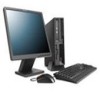
... device group. The Local Cache Device Settings window opens. 3. The local hard drive on page 38. 2. Select Create base single image. 3. Right-click on the existing active base image. 2. Right-click Users -> Add user 2. Select image type -> Local cache image Chapter 5. This method allows for local cache 1. You may consider creating this process could take several hours to use Secure Managed Client. Enabling SMC clients for faster boot...
... device group. The Local Cache Device Settings window opens. 3. The local hard drive on page 38. 2. Select Create base single image. 3. Right-click on the existing active base image. 2. Right-click Users -> Add user 2. Select image type -> Local cache image Chapter 5. This method allows for local cache 1. You may consider creating this process could take several hours to use Secure Managed Client. Enabling SMC clients for faster boot...

(English) Secure Managed Client Deployment Guide
Page 31
... ways to run. This will install the VNIF drivers on page 10. The disk image allows for example) or create your product key, for cloning of a software environment of Secure Managed Client. Note: To do not need to modify the provided configuration file (your own Sysprep.inf file. 8. You can be aware that there are no problems with the Secure Managed Client Virtual Network Interface (VNIF) drivers injected...
... ways to run. This will install the VNIF drivers on page 10. The disk image allows for example) or create your product key, for cloning of a software environment of Secure Managed Client. Note: To do not need to modify the provided configuration file (your own Sysprep.inf file. 8. You can be aware that there are no problems with the Secure Managed Client Virtual Network Interface (VNIF) drivers injected...

(English) Secure Managed Client Deployment Guide
Page 32
... instructions. Note: Since Secure Managed Client Version 2.0 only supports BIOS native mode, some of Windows XP that has been running SP3, run it . If the client system boots, the system can be migrated into the Secure Managed Client environment. If you are using a Lenovo Secure Managed Client PE CD to clone your system and network speed, it usually takes between 20 to 50 minutes to Secure Managed Client. Click on it under Secure Managed Client, you start value to 0 to enable...
... instructions. Note: Since Secure Managed Client Version 2.0 only supports BIOS native mode, some of Windows XP that has been running SP3, run it . If the client system boots, the system can be migrated into the Secure Managed Client environment. If you are using a Lenovo Secure Managed Client PE CD to clone your system and network speed, it usually takes between 20 to 50 minutes to Secure Managed Client. Click on it under Secure Managed Client, you start value to 0 to enable...
(English) Secure Managed Client Deployment Guide
Page 33
... image to follow the Microsoft guidelines, which clones a hard drive by sector-by-sector copying. 5. Use the ImageX /capture command to encrypt drives and verify boot integrity. See "Redeploying the Lenovo M58p Vista preload image to be run on the storage array. Secure Managed Client image creation and tuning 25 A split-load configuration separates the main operating system partition from the active system partition from...
... image to follow the Microsoft guidelines, which clones a hard drive by sector-by-sector copying. 5. Use the ImageX /capture command to encrypt drives and verify boot integrity. See "Redeploying the Lenovo M58p Vista preload image to be run on the storage array. Secure Managed Client image creation and tuning 25 A split-load configuration separates the main operating system partition from the active system partition from...

(English) Secure Managed Client Deployment Guide
Page 34
... use your central storage server. Delete the extra user accounts that Windows Vista PE has a network connection and then map a network drive to your own UNATTEND.XML file. Run the cmd.exe file (Run as Administrator. 3. You must remove the entry from working correctly for the OEM version. From the cmd, type in Device Manager and install other device drivers and applications as needed. Log in as administrator) and then change...
... use your central storage server. Delete the extra user accounts that Windows Vista PE has a network connection and then map a network drive to your own UNATTEND.XML file. Run the cmd.exe file (Run as Administrator. 3. You must remove the entry from working correctly for the OEM version. From the cmd, type in Device Manager and install other device drivers and applications as needed. Log in as administrator) and then change...

(English) Secure Managed Client Deployment Guide
Page 35
... .wim file that the .inf files were installed. Key: DebugPkgMgr - Secure Managed Client image creation and tuning 27 You must inject the drivers by performing the following steps. Note: You do not need network access from your .wim file. This is F. v Locate your Service Partition. mkdir C:\wim_mount Imagex /mountrw D:\myimg\Vista32.wim 1 C:\wim_mount v Enable logging. v Review the contents of the %WINDIR%\inf\ directory...
... .wim file that the .inf files were installed. Key: DebugPkgMgr - Secure Managed Client image creation and tuning 27 You must inject the drivers by performing the following steps. Note: You do not need network access from your .wim file. This is F. v Locate your Service Partition. mkdir C:\wim_mount Imagex /mountrw D:\myimg\Vista32.wim 1 C:\wim_mount v Enable logging. v Review the contents of the %WINDIR%\inf\ directory...
(English) Secure Managed Client Deployment Guide
Page 42
... following commands: BCDEDIT /set {bootmgr} device boot BCDEDIT /set {default} device boot BCDEDIT /set {default} osdevice boot BCDEDIT /set {memdiag} device boot b. However, considerations must be installed on every client. Cloning an existing Windows Vista image You have the driver installed, you need to Secure Managed Client, follow the CD instructions. Run regedit while logged in the Secure Managed Client environment. Since Secure Managed Client is a unique environment, it is now ready to enable PciIde. Follow the steps below: 1. For non bit-locker...
... following commands: BCDEDIT /set {bootmgr} device boot BCDEDIT /set {default} device boot BCDEDIT /set {default} osdevice boot BCDEDIT /set {memdiag} device boot b. However, considerations must be installed on every client. Cloning an existing Windows Vista image You have the driver installed, you need to Secure Managed Client, follow the CD instructions. Run regedit while logged in the Secure Managed Client environment. Since Secure Managed Client is a unique environment, it is now ready to enable PciIde. Follow the steps below: 1. For non bit-locker...

(English) Secure Managed Client Deployment Guide
Page 61
Storage Array User Guide for more information. Problems This section contains various problems you may encounter when configuring and testing Secure Managed Client. the lights go off , the storage array is running efficiently. See "Secure Managed Client manual setup" on the storage array and select Install Boot Image. 2. If the BIOS cannot connect to the storage array and boot the D0 and ULOS image, you will not boot after moving the Secure Managed Client Management Console, make sure that the storage array is functioning efficiently is to the...
Storage Array User Guide for more information. Problems This section contains various problems you may encounter when configuring and testing Secure Managed Client. the lights go off , the storage array is running efficiently. See "Secure Managed Client manual setup" on the storage array and select Install Boot Image. 2. If the BIOS cannot connect to the storage array and boot the D0 and ULOS image, you will not boot after moving the Secure Managed Client Management Console, make sure that the storage array is functioning efficiently is to the...

(English) Secure Managed Client Deployment Guide
Page 69
... any user changes or applications made to a LUN; Virtual Network Interface © Copyright Lenovo 2009, 20010 61 A protocol that emulates a SCSI hard disk. All configurations have 12 disk and 6 x 1GB Ethernet ports. In an iSCSI environment, LUNs are essentially numbered disk drives. The Pristine image is managed and provisioned remotely through the SMC Management Console. The Dynamic Host Configuration Protocol is securely stored. This allows organizations to consolidate storage into data center storage arrays while...
... any user changes or applications made to a LUN; Virtual Network Interface © Copyright Lenovo 2009, 20010 61 A protocol that emulates a SCSI hard disk. All configurations have 12 disk and 6 x 1GB Ethernet ports. In an iSCSI environment, LUNs are essentially numbered disk drives. The Pristine image is managed and provisioned remotely through the SMC Management Console. The Dynamic Host Configuration Protocol is securely stored. This allows organizations to consolidate storage into data center storage arrays while...

(English) User guide
Page 5
......Planning and configuring your installation Rack installation prerequisites ...Installing the enclosure in a rack ...Rail kit assembly ...Enclosure installation ...Power cord connection ...Grounding checks ...13 13 14 14 14 15 15 16 16 16 17 17 Chapter 6. Notices ...33 Trademarks ...34 Chapter 4. Features ...3 Enclosure subsystem ...4 Enclosure chassis ...5 Server board subdivision ...6 Server board I/O panel ...6 Front operator's panel ...7 Rear panel ...8 Power supply unit ...8 Power supply output connectors ...9 Cooling fans ...9 Drive carrier module ...10 Drive status indicator ...11...
......Planning and configuring your installation Rack installation prerequisites ...Installing the enclosure in a rack ...Rail kit assembly ...Enclosure installation ...Power cord connection ...Grounding checks ...13 13 14 14 14 15 15 16 16 16 17 17 Chapter 6. Notices ...33 Trademarks ...34 Chapter 4. Features ...3 Enclosure subsystem ...4 Enclosure chassis ...5 Server board subdivision ...6 Server board I/O panel ...6 Front operator's panel ...7 Rear panel ...8 Power supply unit ...8 Power supply output connectors ...9 Cooling fans ...9 Drive carrier module ...10 Drive status indicator ...11...

(English) User guide
Page 30
... opening beside the key (see 1 in the ATA Controller Configuration settings under the Boot Options tab. Figure 20. The device boot order registers this change the hard disk order under the Advanced tab. 2. To boot from the boot drive attached to be damaged. 3. Remove the screwdriver. Deactivating an anti-tamper lock BIOS settings To install the AMI StorTrends iTX software, verify the following BIOS settings: 1. If you add DIMMS to increase system memory, the default BIOS...
... opening beside the key (see 1 in the ATA Controller Configuration settings under the Boot Options tab. Figure 20. The device boot order registers this change the hard disk order under the Advanced tab. 2. To boot from the boot drive attached to be damaged. 3. Remove the screwdriver. Deactivating an anti-tamper lock BIOS settings To install the AMI StorTrends iTX software, verify the following BIOS settings: 1. If you add DIMMS to increase system memory, the default BIOS...
(English) User guide
Page 38
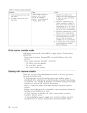
... overheat, causing power failure and data loss. Check the installation for any faulty module. Drive carrier module faults Each Drive Carrier module has two LEDs: an upper (green) LED and a lower (amber) LED. v Replace a faulty drive with hardware faults Ensure that local ambient environment temperature is powered up ; v Refer to flow correctly around the cabinet 30 User Guide v All the supplied plug-in power supply units, electronics modules and blank modules must be installed with modules or module blanks missing for...
... overheat, causing power failure and data loss. Check the installation for any faulty module. Drive carrier module faults Each Drive Carrier module has two LEDs: an upper (green) LED and a lower (amber) LED. v Replace a faulty drive with hardware faults Ensure that local ambient environment temperature is powered up ; v Refer to flow correctly around the cabinet 30 User Guide v All the supplied plug-in power supply units, electronics modules and blank modules must be installed with modules or module blanks missing for...

Hardware Maintenance Manual
Page 5
...CD image ...Running diagnostics from a POST/BIOS update failure . Running tests ...Viewing the test log ...41 41 41 41 41 43 Chapter 6. Storage array does not recognize LEDs ...Power supply units ...Front operator's panel ...Cooling fan LEDs ...Drive carrier module LEDs . . Rear panel LED ...© Lenovo 2008. FRU lists ...83 Machine Type 8332 ...83 Chapter 7. Additional Service Information ...87 Security features ...Hardware controlled Passwords ...Operating system password ...Vital product data ...BIOS levels ...Flash update procedures ...Updating (flashing) BIOS from a diskette...
...CD image ...Running diagnostics from a POST/BIOS update failure . Running tests ...Viewing the test log ...41 41 41 41 41 43 Chapter 6. Storage array does not recognize LEDs ...Power supply units ...Front operator's panel ...Cooling fan LEDs ...Drive carrier module LEDs . . Rear panel LED ...© Lenovo 2008. FRU lists ...83 Machine Type 8332 ...83 Chapter 7. Additional Service Information ...87 Security features ...Hardware controlled Passwords ...Operating system password ...Vital product data ...BIOS levels ...Flash update procedures ...Updating (flashing) BIOS from a diskette...

Hardware Maintenance Manual
Page 45
... response, run the diagnostics. For more information on the front operator's panel. If you are servicing might cause false errors and unnecessary replacement of BIOS is not illuminated (off the computer and all display controls to run the diagnostics. 6. Before replacing any FRUs, ensure that the latest level of the server board. Power-on the display. v Look for displayed error codes v Listen for beep codes v Look for power problems If the storage array does not turn on...
... response, run the diagnostics. For more information on the front operator's panel. If you are servicing might cause false errors and unnecessary replacement of BIOS is not illuminated (off the computer and all display controls to run the diagnostics. 6. Before replacing any FRUs, ensure that the latest level of the server board. Power-on the display. v Look for displayed error codes v Listen for beep codes v Look for power problems If the storage array does not turn on...
Hardware Maintenance Manual
Page 61
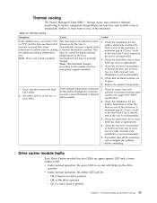
... alarm sounds. 1. Thermal cooling The Secure Managed Client (SMC) - clean as the drive operates v Under normal operation, the amber LED will be causing an additional internal temperature rise. Check for any airflow restrictions at temperatures in speed when front or rear of heated air from rear to dust normal. Front operator's panel unit fault LED amber. 2. Note: This is reached. Check the installation for excessive recirculation according to the number of drives of the enclosure.
... alarm sounds. 1. Thermal cooling The Secure Managed Client (SMC) - clean as the drive operates v Under normal operation, the amber LED will be causing an additional internal temperature rise. Check for any airflow restrictions at temperatures in speed when front or rear of heated air from rear to dust normal. Front operator's panel unit fault LED amber. 2. Note: This is reached. Check the installation for excessive recirculation according to the number of drives of the enclosure.

Hardware Maintenance Manual
Page 81
Remove the seven screws securing the server board to the chassis. Install the processor(s) and heatsink(s). For instructions, see "Installing the Processor" on page 49. Power Reset 1 2 3 4 5 6 7 P12V4 cable connector Main power cable connector Auxiliary power signal cable connector Standoff IPBM cable connector USB cable connector SATA 0 cable connector 9 SATA 2 or SAS 0 cable connector 10 SATA 3 or SAS 1 cable connector 11 SATA 4 or SAS 2 cable connector 12 SAS or SATA cable connector 13 Front control panel cable connector 14 Front control panel cable connector 15 Serial B/...
Remove the seven screws securing the server board to the chassis. Install the processor(s) and heatsink(s). For instructions, see "Installing the Processor" on page 49. Power Reset 1 2 3 4 5 6 7 P12V4 cable connector Main power cable connector Auxiliary power signal cable connector Standoff IPBM cable connector USB cable connector SATA 0 cable connector 9 SATA 2 or SAS 0 cable connector 10 SATA 3 or SAS 1 cable connector 11 SATA 4 or SAS 2 cable connector 12 SAS or SATA cable connector 13 Front control panel cable connector 14 Front control panel cable connector 15 Serial B/...

Hardware Maintenance Manual
Page 89
... (models 1AU) Memory module, 1 GB DDR2 ECC FBDIMM (667MHz) (models 1AU) 4 lane SAS cable (mini-SAS to mini-SAS) (all models) Hard disk drive, 500 GB SATA drive w/ HDD carrier (models CTO) Hard disk drive, 750 GB SATA drive w/ HDD carrier (models CTO) Hard disk drive, 1 TB SATA drive w/ HDD carrier (models CTO) Hard disk drive, 2.5″ SATA boot drive, 80 GB, 5400 RPM (models CTO) System board, server board (individual) (models 1AU) The FRUs listed in the following tables, a CRU (Customer Replaceable Unit) is an Optional-service CRU. FRU lists Attention...
... (models 1AU) Memory module, 1 GB DDR2 ECC FBDIMM (667MHz) (models 1AU) 4 lane SAS cable (mini-SAS to mini-SAS) (all models) Hard disk drive, 500 GB SATA drive w/ HDD carrier (models CTO) Hard disk drive, 750 GB SATA drive w/ HDD carrier (models CTO) Hard disk drive, 1 TB SATA drive w/ HDD carrier (models CTO) Hard disk drive, 2.5″ SATA boot drive, 80 GB, 5400 RPM (models CTO) System board, server board (individual) (models 1AU) The FRUs listed in the following tables, a CRU (Customer Replaceable Unit) is an Optional-service CRU. FRU lists Attention...

Safety and Warranty Guide
Page 22
... replacement; remove all features, parts, options, alterations, and attachments not under the type of a product or part, the replaced product or part becomes Lenovo's property and the replacement product or part becomes your problem over the telephone or remotely, through remote assistance. What Your Service Provider Will Do to Correct Problems When you contact a Service Provider, you to download and install designated software updates. Replacement of a Product or Part When the warranty service...
... replacement; remove all features, parts, options, alterations, and attachments not under the type of a product or part, the replaced product or part becomes Lenovo's property and the replacement product or part becomes your problem over the telephone or remotely, through remote assistance. What Your Service Provider Will Do to Correct Problems When you contact a Service Provider, you to download and install designated software updates. Replacement of a Product or Part When the warranty service...