
Hardware Maintenance Manual
Page 3
...on password 24 Supervisor password 24 Power management 25 Screen blank mode 25 Sleep (standby) mode 25 Lenovo Z/P Series 26 Specifications 26 Status indicators 28 Function key combinations 30 FRU replacement notices 31 Screw ...and replacing an FRU 32 1010 Keyboard 33 1020 Optical drive 36 1030 Base cover 39 1040 Battery pack 44 1050 Hard disk drive 46 1060 PCI Express Mini Card for wireless LAN 48 1070... assembly and Heat Sink assembly 52 1090 CPU 56 1100 ODD board and LED board (Z500/P500 58 1110 Speakers 60 1120 System board 63 1130 Keyboard bezel 67 1140 LCD unit 69 1150...
...on password 24 Supervisor password 24 Power management 25 Screen blank mode 25 Sleep (standby) mode 25 Lenovo Z/P Series 26 Specifications 26 Status indicators 28 Function key combinations 30 FRU replacement notices 31 Screw ...and replacing an FRU 32 1010 Keyboard 33 1020 Optical drive 36 1030 Base cover 39 1040 Battery pack 44 1050 Hard disk drive 46 1060 PCI Express Mini Card for wireless LAN 48 1070... assembly and Heat Sink assembly 52 1090 CPU 56 1100 ODD board and LED board (Z500/P500 58 1110 Speakers 60 1120 System board 63 1130 Keyboard bezel 67 1140 LCD unit 69 1150...

Hardware Maintenance Manual
Page 9
...without first correcting the problem. A third-wire ground connector in the parts list. Check inside the unit for any obvious non-Lenovo alterations. As each machine was designed and built, required safety items were installed to assist you can cause serious or fatal electrical... safety of fire or smoke damage. 8. Check for any obvious unsafe conditions, such as to measure third-wire ground continuity for cracked or bulging batteries. 5. Disconnect the power cord. 3. Check for worn, frayed, or pinched cables. 9. Checklist: 1. Check exterior covers for : a. Insulation ...
...without first correcting the problem. A third-wire ground connector in the parts list. Check inside the unit for any obvious non-Lenovo alterations. As each machine was designed and built, required safety items were installed to assist you can cause serious or fatal electrical... safety of fire or smoke damage. 8. Check for any obvious unsafe conditions, such as to measure third-wire ground continuity for cracked or bulging batteries. 5. Disconnect the power cord. 3. Check for worn, frayed, or pinched cables. 9. Checklist: 1. Check exterior covers for : a. Insulation ...
Hardware Maintenance Manual
Page 10
... and correct system function. When working on your body. •• Prevent the part from touching your skin to eliminate static on a double-insulated or battery-operated system, use coax or connectoroutside shells on ac-operated computers. Proper grounding of the electrical outlet can occur when there is insulative and retains...
... and correct system function. When working on your body. •• Prevent the part from touching your skin to eliminate static on a double-insulated or battery-operated system, use coax or connectoroutside shells on ac-operated computers. Proper grounding of the electrical outlet can occur when there is insulative and retains...

Hardware Maintenance Manual
Page 25
...: Output voltage for correct continuity and installation. •• If the computer does not charge during operation, use a discharged battery pack or a battery pack that the battery pack supplies power when you are here because the computer fails only when the AC adapter is acceptable, do the following: &#...8226;• Replace the system board. •• If the problem continues, go to "Lenovo Z/P Series" on the...
...: Output voltage for correct continuity and installation. •• If the computer does not charge during operation, use a discharged battery pack or a battery pack that the battery pack supplies power when you are here because the computer fails only when the AC adapter is acceptable, do the following: &#...8226;• Replace the system board. •• If the problem continues, go to "Lenovo Z/P Series" on the...
Hardware Maintenance Manual
Page 26
Z/P Series Hardware Maintenance Manual Perform operational charging. If the charge indicator or icon is still off, replace the battery pack. If the charge indicator still does not light on , remove the battery pack and let it return to room temperature. If the battery status indicator or icon does not light on , replace the system board. Reinstall the battery pack. Then reinstall the battery pack. 22
Z/P Series Hardware Maintenance Manual Perform operational charging. If the charge indicator or icon is still off, replace the battery pack. If the charge indicator still does not light on , remove the battery pack and let it return to room temperature. If the battery status indicator or icon does not light on , replace the system board. Reinstall the battery pack. Then reinstall the battery pack. 22

Hardware Maintenance Manual
Page 29
... any operation with the keyboard, the hard disk, the parallel connector, or the diskette drive within that time. •• If the battery indicator is amber, indicating that the battery power is powered off . To end screen blank mode and resume normal operation, press any input immediately after it enters sleep (standby...
... any operation with the keyboard, the hard disk, the parallel connector, or the diskette drive within that time. •• If the battery indicator is amber, indicating that the battery power is powered off . To end screen blank mode and resume normal operation, press any input immediately after it enters sleep (standby...

Hardware Maintenance Manual
Page 31
Specifications (continued) Feature I/O port Audio Ethernet (on the system board) PCI Express Mini Card slot Bluetooth wireless Keyboard Touch pad Integrated camera Battery AC adapter Pre-installed operating system Description • Combo audio jack × 1 • RJ45 × 1 • HDMI port × 1 • USB 2.0 port × 2, USB 3.0 port &#... 0.3 Mega • 4 cell, 41.6 Wh or 48 Wh • 20 V, 65 W or 90 W • Win8 (Win8 EM, Win8 MM, Win8 PRC and Win8 Professionalt) 27 Lenovo Z/P Series Table 1.
Specifications (continued) Feature I/O port Audio Ethernet (on the system board) PCI Express Mini Card slot Bluetooth wireless Keyboard Touch pad Integrated camera Battery AC adapter Pre-installed operating system Description • Combo audio jack × 1 • RJ45 × 1 • HDMI port × 1 • USB 2.0 port × 2, USB 3.0 port &#... 0.3 Mega • 4 cell, 41.6 Wh or 48 Wh • 20 V, 65 W or 90 W • Win8 (Win8 EM, Win8 MM, Win8 PRC and Win8 Professionalt) 27 Lenovo Z/P Series Table 1.
Hardware Maintenance Manual
Page 33
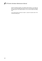
... mode and is fully charged. However, charging will stop blinking. The battery has less than 20% charge. Z500/P500 Lenovo Z/P Series 1 2 Table 2. The battery has more than 5% charge. 29 The battery has between 20% and 80% charge. The battery has between 5% and 20% charge. The battery has less than 80% charge. The computer is powered on. When...
... mode and is fully charged. However, charging will stop blinking. The battery has less than 20% charge. Z500/P500 Lenovo Z/P Series 1 2 Table 2. The battery has more than 5% charge. 29 The battery has between 20% and 80% charge. The battery has between 5% and 20% charge. The battery has less than 80% charge. The computer is powered on. When...

Hardware Maintenance Manual
Page 48
... connector in the parts list for your computer. Any other battery could ignite or explode. Z/P Series Hardware Maintenance Manual 1040 Battery pack For access, remove these FRUs in order: •• "1010 Keyboard" on page 33 •• "1020 Optical drive" on page 36... •• "1030 Base cover" on page 39 DANGER Only use the battery specified in the direction shown by arrow 1, remove the two screws 2. Z400 2 2 1 Z500/P500 2 2 1 Step Screw (quantity) 2 M2.5 × 3 mm, flat-head, nylok-coated (2) Color Torque black 3.0+/-0.3 ...
... connector in the parts list for your computer. Any other battery could ignite or explode. Z/P Series Hardware Maintenance Manual 1040 Battery pack For access, remove these FRUs in order: •• "1010 Keyboard" on page 33 •• "1020 Optical drive" on page 36... •• "1030 Base cover" on page 39 DANGER Only use the battery specified in the direction shown by arrow 1, remove the two screws 2. Z400 2 2 1 Z500/P500 2 2 1 Step Screw (quantity) 2 M2.5 × 3 mm, flat-head, nylok-coated (2) Color Torque black 3.0+/-0.3 ...

Hardware Maintenance Manual
Page 49
Z400 3 Z500/P500 3 When installing: Make sure the battery pack connector is attached firmly. 45 Lenovo Z/P Series Figure 4. Removal steps of battery pack (continued) Remove the battery pack in the direction shown by arrow 3.
Z400 3 Z500/P500 3 When installing: Make sure the battery pack connector is attached firmly. 45 Lenovo Z/P Series Figure 4. Removal steps of battery pack (continued) Remove the battery pack in the direction shown by arrow 3.

Hardware Maintenance Manual
Page 50
Improper handling can cause damages and permanent loss of hard disk drive Remove the four screws 1. Figure 5. Z400 1 1 1 Z500/P500 1 1 1 Step Screw (quantity) 1 M2.5 × 3 mm, flat-head, nylok-coated (4) Color Torque Black 3.0+/-0.3 kgf*cm 46 The hard disk drive is in suspend mode. Removal ...;• "1010 Keyboard" on page 33 •• "1020 Optical drive" on page 36 •• "1030 Base cover" on page 39 •• "1040 Battery pack" on it .
Improper handling can cause damages and permanent loss of hard disk drive Remove the four screws 1. Figure 5. Z400 1 1 1 Z500/P500 1 1 1 Step Screw (quantity) 1 M2.5 × 3 mm, flat-head, nylok-coated (4) Color Torque Black 3.0+/-0.3 kgf*cm 46 The hard disk drive is in suspend mode. Removal ...;• "1010 Keyboard" on page 33 •• "1020 Optical drive" on page 36 •• "1030 Base cover" on page 39 •• "1040 Battery pack" on it .

Hardware Maintenance Manual
Page 52
... 1060 PCI Express Mini Card for wireless LAN Disconnect the two wireless LAN cables (black, white) 1, and then remove the screw 2. Z400 2 1 Z500/P500 2 1 In step 1, unplug the jacks by using the removal tool antenna RF connector (P/N: 08K7159), or pick up the connectors with your fingers and gently ..."1010 Keyboard" on page 33 •• "1020 Optical drive" on page 36 •• "1030 Base cover" on page 39 •• "1040 Battery pack" on page 44 Figure 6. Removal steps of PCI Express Mini Card for wireless LAN For access, remove these FRUs in the direction shown by...
... 1060 PCI Express Mini Card for wireless LAN Disconnect the two wireless LAN cables (black, white) 1, and then remove the screw 2. Z400 2 1 Z500/P500 2 1 In step 1, unplug the jacks by using the removal tool antenna RF connector (P/N: 08K7159), or pick up the connectors with your fingers and gently ..."1010 Keyboard" on page 33 •• "1020 Optical drive" on page 36 •• "1030 Base cover" on page 39 •• "1040 Battery pack" on page 44 Figure 6. Removal steps of PCI Express Mini Card for wireless LAN For access, remove these FRUs in the direction shown by...

Hardware Maintenance Manual
Page 54
Removal steps of DIMM Release the two latches on page 44 Figure 7. Z400 1 1 2 50 Z/P Series Hardware Maintenance Manual 1070 DIMM For access, remove these FRUs in order: •• "1010 Keyboard" on page 33 •• "1020 Optical drive" on page 36 •• "1030 Base cover" on page 39 •• "1040 Battery pack" on both edges of the socket at the same time in the direction shown by arrows 1, and then unplug the DIMM in the direction shown by arrow 2.
Removal steps of DIMM Release the two latches on page 44 Figure 7. Z400 1 1 2 50 Z/P Series Hardware Maintenance Manual 1070 DIMM For access, remove these FRUs in order: •• "1010 Keyboard" on page 33 •• "1020 Optical drive" on page 36 •• "1030 Base cover" on page 39 •• "1040 Battery pack" on both edges of the socket at the same time in the direction shown by arrows 1, and then unplug the DIMM in the direction shown by arrow 2.

Hardware Maintenance Manual
Page 56
...;• "1010 Keyboard" on page 33 •• "1020 Optical drive" on page 36 •• "1030 Base cover" on page 39 •• "1040 Battery pack" on page 44 Figure 8. Z400 3 2 2 3 4 1 Step Screw (quantity) 2 M2 × 3.2, flat-head, nylok-coated (3) 3 M2 × 3, flat-head, nylok-coated (2) 4 M2.5 × 6, flat-head...
...;• "1010 Keyboard" on page 33 •• "1020 Optical drive" on page 36 •• "1030 Base cover" on page 39 •• "1040 Battery pack" on page 44 Figure 8. Z400 3 2 2 3 4 1 Step Screw (quantity) 2 M2 × 3.2, flat-head, nylok-coated (3) 3 M2 × 3, flat-head, nylok-coated (2) 4 M2.5 × 6, flat-head...

Hardware Maintenance Manual
Page 60
...;• "1010 Keyboard" on page 33 •• "1020 Optical drive" on page 36 •• "1030 Base cover" on page 39 •• "1040 Battery pack" on page 44 •• "1050 Hard disk drive" on page 46 •• "1060 PCI Express Mini Card for wireless LAN" on page...
...;• "1010 Keyboard" on page 33 •• "1020 Optical drive" on page 36 •• "1030 Base cover" on page 39 •• "1040 Battery pack" on page 44 •• "1050 Hard disk drive" on page 46 •• "1060 PCI Express Mini Card for wireless LAN" on page...

Hardware Maintenance Manual
Page 62
Z/P Series Hardware Maintenance Manual 1100 ODD board and LED board (Z500/P500) For access, remove these FRUs in the direction shown by arrows 1 2. Remove a total of ODD board and LED board Detach the two FPC connectors in ...;• "1010 Keyboard" on page 33 •• "1020 Optical drive" on page 36 •• "1030 Base cover" on page 39 •• "1040 Battery pack" on page 44 •• "1050 Hard disk drive" on page 46 •• "1060 PCI Express Mini Card for wireless LAN" on page...
Z/P Series Hardware Maintenance Manual 1100 ODD board and LED board (Z500/P500) For access, remove these FRUs in the direction shown by arrows 1 2. Remove a total of ODD board and LED board Detach the two FPC connectors in ...;• "1010 Keyboard" on page 33 •• "1020 Optical drive" on page 36 •• "1030 Base cover" on page 39 •• "1040 Battery pack" on page 44 •• "1050 Hard disk drive" on page 46 •• "1060 PCI Express Mini Card for wireless LAN" on page...

Hardware Maintenance Manual
Page 64
...;• "1010 Keyboard" on page 33 •• "1020 Optical drive" on page 36 •• "1030 Base cover" on page 39 •• "1040 Battery pack" on page 44 •• "1050 Hard disk drive" on page 46 •• "1060 PCI Express Mini Card for wireless LAN" on page... 48 •• "1080 Fan assembly and Heat Sink assembly" on page 52 •• "1100 ODD board and LED board (Z500/P500)" on page 58 Figure 11. Z400 2 2 2 2 1 60 Remove the four screws 2.
...;• "1010 Keyboard" on page 33 •• "1020 Optical drive" on page 36 •• "1030 Base cover" on page 39 •• "1040 Battery pack" on page 44 •• "1050 Hard disk drive" on page 46 •• "1060 PCI Express Mini Card for wireless LAN" on page... 48 •• "1080 Fan assembly and Heat Sink assembly" on page 52 •• "1100 ODD board and LED board (Z500/P500)" on page 58 Figure 11. Z400 2 2 2 2 1 60 Remove the four screws 2.

Hardware Maintenance Manual
Page 67
...; "1020 Optical drive" on page 36 •• "1030 Base cover" on page 39 •• "1040 Battery pack" on page 44 •• "1050 Hard disk drive" on page 46 •• "1060 PCI Express... mind. • Be careful not to put it only on page 60 Figure 12. Z400 1 2 1 2 63 Lenovo Z/P Series 1120 System board Important notices for wireless LAN" on page 48 •• "1080 Fan assembly and Heat..." on page 52 •• "1100 ODD board and LED board (Z500/P500)" on page 58 •• "1110 Speakers" on a padded surface such as an ESD mat or conductive ...
...; "1020 Optical drive" on page 36 •• "1030 Base cover" on page 39 •• "1040 Battery pack" on page 44 •• "1050 Hard disk drive" on page 46 •• "1060 PCI Express... mind. • Be careful not to put it only on page 60 Figure 12. Z400 1 2 1 2 63 Lenovo Z/P Series 1120 System board Important notices for wireless LAN" on page 48 •• "1080 Fan assembly and Heat..." on page 52 •• "1100 ODD board and LED board (Z500/P500)" on page 58 •• "1110 Speakers" on a padded surface such as an ESD mat or conductive ...

Hardware Maintenance Manual
Page 71
Lenovo Z/P Series 1130 Keyboard bezel For access, remove these FRUs in the direction shown by arrows 2. 2 2 67 Removal ... page 33 •• "1020 Optical drive" on page 36 •• "1030 Base cover" on page 39 •• "1040 Battery pack" on page 44 •• "1050 Hard disk drive" on page 46 •• "1060 PCI Express Mini Card for wireless LAN..."1080 Fan assembly and Heat Sink assembly" on page 52 •• "1100 ODD board and LED board (Z500/P500)" on page 58 •• "1110 Speakers" on page 60 •• "1120 System board" on page 63 Figure 13.
Lenovo Z/P Series 1130 Keyboard bezel For access, remove these FRUs in the direction shown by arrows 2. 2 2 67 Removal ... page 33 •• "1020 Optical drive" on page 36 •• "1030 Base cover" on page 39 •• "1040 Battery pack" on page 44 •• "1050 Hard disk drive" on page 46 •• "1060 PCI Express Mini Card for wireless LAN..."1080 Fan assembly and Heat Sink assembly" on page 52 •• "1100 ODD board and LED board (Z500/P500)" on page 58 •• "1110 Speakers" on page 60 •• "1120 System board" on page 63 Figure 13.

Hardware Maintenance Manual
Page 73
... six screws (five 1 and one 1'). 1' 1 1 69 Lenovo Z/P Series 1140 LCD unit For access, remove these FRUs in order: •• "1010 Keyboard" on page 33 •• "1020 Optical drive" on page 36 •• "1030 Base cover" on page 39 •• "1040 Battery pack" on page 44 •• "1050... DIMM" on page 50 •• "1080 Fan assembly and Heat Sink assembly" on page 52 •• "1100 ODD board and LED board (Z500/P500)" on page 58 •• "1110 Speakers" on page 60 •• "1120 System board" on page 63 •• "1130 Keyboard bezel" on ...
... six screws (five 1 and one 1'). 1' 1 1 69 Lenovo Z/P Series 1140 LCD unit For access, remove these FRUs in order: •• "1010 Keyboard" on page 33 •• "1020 Optical drive" on page 36 •• "1030 Base cover" on page 39 •• "1040 Battery pack" on page 44 •• "1050... DIMM" on page 50 •• "1080 Fan assembly and Heat Sink assembly" on page 52 •• "1100 ODD board and LED board (Z500/P500)" on page 58 •• "1110 Speakers" on page 60 •• "1120 System board" on page 63 •• "1130 Keyboard bezel" on ...


