
Hardware Maintenance Manual
Page 10
...Do not work on suitable rubber mats (obtained locally, if necessary) to power-off controls, is near equipment that contain small conductive fibers to decrease electrostatic discharges. keep the other hand in the safety sections of mat to work with powered-on ...electrical equipment. v Regularly inspect and maintain your body. - Observe the following precautions: - v Find the room emergency power-off . 4 Lenovo 3000 J Series Remember: Another person must be a complete circuit to lock the wall box in the installation and configuration procedures. v Never assume...
...Do not work on suitable rubber mats (obtained locally, if necessary) to power-off controls, is near equipment that contain small conductive fibers to decrease electrostatic discharges. keep the other hand in the safety sections of mat to work with powered-on ...electrical equipment. v Regularly inspect and maintain your body. - Observe the following precautions: - v Find the room emergency power-off . 4 Lenovo 3000 J Series Remember: Another person must be a complete circuit to lock the wall box in the installation and configuration procedures. v Never assume...
Hardware Maintenance Manual
Page 100
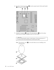
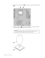
Note: The protective cover 3 is not used unless you must touch the microprocessor, touch only the sides. To remove the microprocessor 2 from the system board socket by lifting it straight up and out of the microprocessor. Using the vacuum pen 1 , remove the microprocessor 2 from the system board, lift the small handle 3 and open the retainer 1 . 11. Important Do not touch the gold contacts on the bottom of the socket. If you are installing a new microprocessor. 94 Lenovo 3000 J Series 10.
Note: The protective cover 3 is not used unless you must touch the microprocessor, touch only the sides. To remove the microprocessor 2 from the system board socket by lifting it straight up and out of the microprocessor. Using the vacuum pen 1 , remove the microprocessor 2 from the system board, lift the small handle 3 and open the retainer 1 . 11. Important Do not touch the gold contacts on the bottom of the socket. If you are installing a new microprocessor. 94 Lenovo 3000 J Series 10.
Hardware Maintenance Manual
Page 104
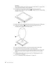
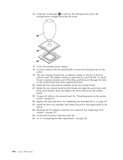
To install the microprocessor on the new system board, position the microprocessor so that the small triangle 1 is aligned with those in the socket. 16. Install the heat sink and fan assembly on page 85 19. See "Identifying parts on the ... into the chassis and align the screw holes with the corresponding triangle on page 111. 98 Lenovo 3000 J Series Using the vacuum pen 1 to "Completing the FRU replacement." on the socket. 13. Make sure that the small handle that secure the system board. 18. Connect all the cables to secure the microprocessor in...
To install the microprocessor on the new system board, position the microprocessor so that the small triangle 1 is aligned with those in the socket. 16. Install the heat sink and fan assembly on page 85 19. See "Identifying parts on the ... into the chassis and align the screw holes with the corresponding triangle on page 111. 98 Lenovo 3000 J Series Using the vacuum pen 1 to "Completing the FRU replacement." on the socket. 13. Make sure that the small handle that secure the system board. 18. Connect all the cables to secure the microprocessor in...
Hardware Maintenance Manual
Page 132
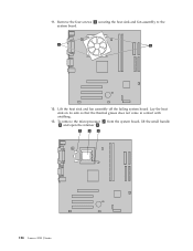
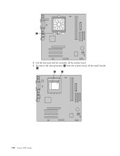
To remove the microprocessor 2 from the system board, lift the small handle 3 and open the retainer 1 . 126 Lenovo 3000 J Series 11. Remove the four screws 1 securing the heat sink and fan assembly to the system board. 12. Lift the heat sink and fan assembly off the failing system board. Lay the heat sink on its side so that the thermal grease does not come in contact with anything. 13.
To remove the microprocessor 2 from the system board, lift the small handle 3 and open the retainer 1 . 126 Lenovo 3000 J Series 11. Remove the four screws 1 securing the heat sink and fan assembly to the system board. 12. Lift the heat sink and fan assembly off the failing system board. Lay the heat sink on its side so that the thermal grease does not come in contact with anything. 13.
Hardware Maintenance Manual
Page 134
Lock the retainer with the small handle to pick up the microprocessor, lower the microprocessor straight down into the chassis and align the screw holes with those in the socket. 19. ... board. 21. Lower the microprocessor retainer. 18. Insert and tighten the screws that were removed. See "Replacing the hard disk drive" on page 143. 128 Lenovo 3000 J Series on page 139. 24. Using the vacuum pen 1 to secure the microprocessor in the chassis. 16.
Lock the retainer with the small handle to pick up the microprocessor, lower the microprocessor straight down into the chassis and align the screw holes with those in the socket. 19. ... board. 21. Lower the microprocessor retainer. 18. Insert and tighten the screws that were removed. See "Replacing the hard disk drive" on page 143. 128 Lenovo 3000 J Series on page 139. 24. Using the vacuum pen 1 to secure the microprocessor in the chassis. 16.
Hardware Maintenance Manual
Page 136
Important Do not touch the gold contacts on the bottom of the socket. To remove the microprocessor 2 from the system board socket by lifting it straight up and out of the microprocessor. 13. Using the vacuum pen 1 , remove the microprocessor from the system board, lift the small handle 1. 14. If you must touch the microprocessor, touch only the sides. 130 Lenovo 3000 J Series
Important Do not touch the gold contacts on the bottom of the socket. To remove the microprocessor 2 from the system board socket by lifting it straight up and out of the microprocessor. 13. Using the vacuum pen 1 , remove the microprocessor from the system board, lift the small handle 1. 14. If you must touch the microprocessor, touch only the sides. 130 Lenovo 3000 J Series
Hardware Maintenance Manual
Page 142
5. Lift the heat sink and fan assembly off the system board. 6. To remove the microprocessor 2 from the system board, lift the small handle 1. 136 Lenovo 3000 J Series
5. Lift the heat sink and fan assembly off the system board. 6. To remove the microprocessor 2 from the system board, lift the small handle 1. 136 Lenovo 3000 J Series