
Hardware Maintenance Manual
Page 3
... password 24 Supervisor password 24 Power management 25 Screen blank mode 25 Sleep (standby) mode 25 Lenovo Z/P Series 26 Specifications 26 Status indicators 28 Function key combinations 30 FRU replacement notices 31 Screw ... replacing an FRU 32 1010 Keyboard 33 1020 Optical drive 36 1030 Base cover 39 1040 Battery pack 44 1050 Hard disk drive 46 1060 PCI Express Mini Card for wireless LAN 48 ...panel and hinges 75 1170 Integrated camera, LCD cable and antenna assembly 80 1180 Power board (Z400 84 Locations 85 Front view and right-side view 85 Bottom and Left-side view 87 ...
... password 24 Supervisor password 24 Power management 25 Screen blank mode 25 Sleep (standby) mode 25 Lenovo Z/P Series 26 Specifications 26 Status indicators 28 Function key combinations 30 FRU replacement notices 31 Screw ... replacing an FRU 32 1010 Keyboard 33 1020 Optical drive 36 1030 Base cover 39 1040 Battery pack 44 1050 Hard disk drive 46 1060 PCI Express Mini Card for wireless LAN 48 ...panel and hinges 75 1170 Integrated camera, LCD cable and antenna assembly 80 1180 Power board (Z400 84 Locations 85 Front view and right-side view 85 Bottom and Left-side view 87 ...

Hardware Maintenance Manual
Page 9
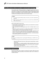
... beginning of every service task. Use good judgment as metal filings, contamination, water or other liquids, or signs of non-Lenovo features or options not covered by this inspection guide is to assist you can cause serious or fatal electrical shock) •&#... unsafe conditions, use good judgment to identify potential safety hazards according to the safety of this inspection guide. Check exterior covers for cracked or bulging batteries. 5. Begin the checks with . 5 Checklist: 1. Remove the cover. 6. Use a meter to protect users and service personnel from injury. ...
... beginning of every service task. Use good judgment as metal filings, contamination, water or other liquids, or signs of non-Lenovo features or options not covered by this inspection guide is to assist you can cause serious or fatal electrical shock) •&#... unsafe conditions, use good judgment to identify potential safety hazards according to the safety of this inspection guide. Check exterior covers for cracked or bulging batteries. 5. Begin the checks with . 5 Checklist: 1. Remove the cover. 6. Use a meter to protect users and service personnel from injury. ...
Hardware Maintenance Manual
Page 10
... use coax or connectoroutside shells on ac-operated computers. When working on your body. •• Prevent the part from touching your skin to eliminate static on a double-insulated or battery-operated system, use have been certified (ISO 9000) as those listed below, to provide protection that are sensitive to electrostatic discharge...
... use coax or connectoroutside shells on ac-operated computers. When working on your body. •• Prevent the part from touching your skin to eliminate static on a double-insulated or battery-operated system, use have been certified (ISO 9000) as those listed below, to provide protection that are sensitive to electrostatic discharge...

Hardware Maintenance Manual
Page 25
...1 Note: Output voltage for correct continuity and installation. •• If the computer does not charge during operation, use a discharged battery pack or a battery pack that the battery pack supplies power when you turn on the computer. 4. Unplug the AC adapter cable from the AC adapter does not always indicate ...the AC adapter. 3. See the following : •• Replace the system board. •• If the problem continues, go to "Lenovo Z/P Series" on page 21 Checking the AC adapter You are servicing. 3. Make sure that has less than 50% of the AC adapter...
...1 Note: Output voltage for correct continuity and installation. •• If the computer does not charge during operation, use a discharged battery pack or a battery pack that the battery pack supplies power when you turn on the computer. 4. Unplug the AC adapter cable from the AC adapter does not always indicate ...the AC adapter. 3. See the following : •• Replace the system board. •• If the problem continues, go to "Lenovo Z/P Series" on page 21 Checking the AC adapter You are servicing. 3. Make sure that has less than 50% of the AC adapter...
Hardware Maintenance Manual
Page 26
If the charge indicator still does not light on , remove the battery pack and let it return to room temperature. If the charge indicator or icon is still off, replace the battery pack. Then reinstall the battery pack. 22 Reinstall the battery pack. If the battery status indicator or icon does not light on , replace the system board. Z/P Series Hardware Maintenance Manual Perform operational charging.
If the charge indicator still does not light on , remove the battery pack and let it return to room temperature. If the charge indicator or icon is still off, replace the battery pack. Then reinstall the battery pack. 22 Reinstall the battery pack. If the battery status indicator or icon does not light on , replace the system board. Z/P Series Hardware Maintenance Manual Perform operational charging.

Hardware Maintenance Manual
Page 29
... any operation with the keyboard, the hard disk, the parallel connector, or the diskette drive within that time. •• If the battery indicator is amber, indicating that the battery power is powered off . Screen blank mode If the time set on the resume timer elapses. Also, in the operating system expires...
... any operation with the keyboard, the hard disk, the parallel connector, or the diskette drive within that time. •• If the battery indicator is amber, indicating that the battery power is powered off . Screen blank mode If the time set on the resume timer elapses. Also, in the operating system expires...

Hardware Maintenance Manual
Page 31
Specifications (continued) Feature I/O port Audio Ethernet (on the system board) PCI Express Mini Card slot Bluetooth wireless Keyboard Touch pad Integrated camera Battery AC adapter Pre-installed operating system Description • Combo audio jack × 1 • RJ45 × 1 • HDMI port × 1 • USB 2.0 port ...• 10/100M • 100/1000M(option) • 2 slot • Combo w/ Wifi, BT 4.0 option • 6 Row, ISO Full Size Keyboard • Multi-touch type • 720P HD or 0.3 Mega • 4 cell, 41.6 Wh or 48 Wh • 20 V, 65 W or 90 W • Win8 (Win8 EM, ...
Specifications (continued) Feature I/O port Audio Ethernet (on the system board) PCI Express Mini Card slot Bluetooth wireless Keyboard Touch pad Integrated camera Battery AC adapter Pre-installed operating system Description • Combo audio jack × 1 • RJ45 × 1 • HDMI port × 1 • USB 2.0 port ...• 10/100M • 100/1000M(option) • 2 slot • Combo w/ Wifi, BT 4.0 option • 6 Row, ISO Full Size Keyboard • Multi-touch type • 720P HD or 0.3 Mega • 4 cell, 41.6 Wh or 48 Wh • 20 V, 65 W or 90 W • Win8 (Win8 EM, ...
Hardware Maintenance Manual
Page 33
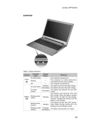
...20%, the blinking color will change to the AC power adapter. The battery has more than 20% charge. The battery has between 5% and 20% charge. The computer is powered on. The battery has more than 80% charge. The computer is in sleep mode ...charging will stop blinking. Status indicators Indicator Indicator status On (solid white) Power Blinking Off On (solid white) On (solid amber) Battery Blinking slowly (white) Blinking slowly (amber) Blinking quickly (amber) Charge Status ------Charging Discharging Discharging Charging Charging Charging/ Discharging Meaning The ...
...20%, the blinking color will change to the AC power adapter. The battery has more than 20% charge. The battery has between 5% and 20% charge. The computer is powered on. The battery has more than 80% charge. The computer is in sleep mode ...charging will stop blinking. Status indicators Indicator Indicator status On (solid white) Power Blinking Off On (solid white) On (solid amber) Battery Blinking slowly (white) Blinking slowly (amber) Blinking quickly (amber) Charge Status ------Charging Discharging Discharging Charging Charging Charging/ Discharging Meaning The ...

Hardware Maintenance Manual
Page 48
...explode. Removal steps of battery pack Detach the battery pack connector in the parts list for your computer. Z400 2 2 1 Z500/P500 2 2 1 Step Screw (quantity) 2 M2.5 × 3 mm, flat-head, nylok-coated (2) Color Torque black 3.0+/-0.3 kgf*cm 44 Z/P Series Hardware Maintenance Manual 1040 Battery pack For access, ...remove these FRUs in order: •• "1010 Keyboard" on page 33 •• "1020 Optical drive" on page 36 •• "1030 Base cover" on page 39 DANGER Only use the battery specified in the direction...
...explode. Removal steps of battery pack Detach the battery pack connector in the parts list for your computer. Z400 2 2 1 Z500/P500 2 2 1 Step Screw (quantity) 2 M2.5 × 3 mm, flat-head, nylok-coated (2) Color Torque black 3.0+/-0.3 kgf*cm 44 Z/P Series Hardware Maintenance Manual 1040 Battery pack For access, ...remove these FRUs in order: •• "1010 Keyboard" on page 33 •• "1020 Optical drive" on page 36 •• "1030 Base cover" on page 39 DANGER Only use the battery specified in the direction...

Hardware Maintenance Manual
Page 49
Z400 3 Z500/P500 3 When installing: Make sure the battery pack connector is attached firmly. 45 Lenovo Z/P Series Figure 4. Removal steps of battery pack (continued) Remove the battery pack in the direction shown by arrow 3.
Z400 3 Z500/P500 3 When installing: Make sure the battery pack connector is attached firmly. 45 Lenovo Z/P Series Figure 4. Removal steps of battery pack (continued) Remove the battery pack in the direction shown by arrow 3.

Hardware Maintenance Manual
Page 50
Improper handling can cause damages and permanent loss of hard disk drive Remove the four screws 1. Z400 1 1 1 Z500/P500 1 1 1 Step Screw (quantity) 1 M2.5 × 3 mm, flat-head, nylok-coated (4) Color Torque Black 3.0+/-0.3 kgf*cm 46 Removal steps of data. • Before removing ...;• "1010 Keyboard" on page 33 •• "1020 Optical drive" on page 36 •• "1030 Base cover" on page 39 •• "1040 Battery pack" on it . Figure 5. Z/P Series Hardware Maintenance Manual 1050 Hard disk drive For access, remove these FRUs in suspend mode.
Improper handling can cause damages and permanent loss of hard disk drive Remove the four screws 1. Z400 1 1 1 Z500/P500 1 1 1 Step Screw (quantity) 1 M2.5 × 3 mm, flat-head, nylok-coated (4) Color Torque Black 3.0+/-0.3 kgf*cm 46 Removal steps of data. • Before removing ...;• "1010 Keyboard" on page 33 •• "1020 Optical drive" on page 36 •• "1030 Base cover" on page 39 •• "1040 Battery pack" on it . Figure 5. Z/P Series Hardware Maintenance Manual 1050 Hard disk drive For access, remove these FRUs in suspend mode.

Hardware Maintenance Manual
Page 52
... Mini Card for wireless LAN For access, remove these FRUs in step 1. Step Screw (quantity) Color 2 M2 × 3 mm, flat-head, nylok-coated (1) (Z400) Black 2 M2 × 2.5 mm, flat-head, nylok-coated (1) (Z500/ Black P500) Torque 1.85+/-0.15 kgf*cm 3.62 kg-cm 48 Notes: wireless LAN...Keyboard" on page 33 •• "1020 Optical drive" on page 36 •• "1030 Base cover" on page 39 •• "1040 Battery pack" on page 44 Figure 6. Z/P Series Hardware Maintenance Manual 1060 PCI Express Mini Card for wireless LAN Disconnect the two wireless LAN cables (black, white...
... Mini Card for wireless LAN For access, remove these FRUs in step 1. Step Screw (quantity) Color 2 M2 × 3 mm, flat-head, nylok-coated (1) (Z400) Black 2 M2 × 2.5 mm, flat-head, nylok-coated (1) (Z500/ Black P500) Torque 1.85+/-0.15 kgf*cm 3.62 kg-cm 48 Notes: wireless LAN...Keyboard" on page 33 •• "1020 Optical drive" on page 36 •• "1030 Base cover" on page 39 •• "1040 Battery pack" on page 44 Figure 6. Z/P Series Hardware Maintenance Manual 1060 PCI Express Mini Card for wireless LAN Disconnect the two wireless LAN cables (black, white...

Hardware Maintenance Manual
Page 54
Z400 1 1 2 50 Removal steps of the socket at the same time in the direction shown by arrows 1, and then unplug the DIMM in the direction shown by arrow 2. Z/P Series Hardware Maintenance Manual 1070 DIMM For access, remove these FRUs in order: •• "1010 Keyboard" on page 33 •• "1020 Optical drive" on page 36 •• "1030 Base cover" on page 39 •• "1040 Battery pack" on both edges of DIMM Release the two latches on page 44 Figure 7.
Z400 1 1 2 50 Removal steps of the socket at the same time in the direction shown by arrows 1, and then unplug the DIMM in the direction shown by arrow 2. Z/P Series Hardware Maintenance Manual 1070 DIMM For access, remove these FRUs in order: •• "1010 Keyboard" on page 33 •• "1020 Optical drive" on page 36 •• "1030 Base cover" on page 39 •• "1040 Battery pack" on both edges of DIMM Release the two latches on page 44 Figure 7.

Hardware Maintenance Manual
Page 56
Z400 3 2 2 3 4 1 Step Screw (quantity) 2 M2 × 3.2, flat-head, nylok-coated (3) 3 M2 × 3, flat-head, nylok-coated (2) 4 M2.5 × 6, flat-head, nylok-coated (1) Color Torque Black 1.85+/-0....;• "1010 Keyboard" on page 33 •• "1020 Optical drive" on page 36 •• "1030 Base cover" on page 39 •• "1040 Battery pack" on page 44 Figure 8.
Z400 3 2 2 3 4 1 Step Screw (quantity) 2 M2 × 3.2, flat-head, nylok-coated (3) 3 M2 × 3, flat-head, nylok-coated (2) 4 M2.5 × 6, flat-head, nylok-coated (1) Color Torque Black 1.85+/-0....;• "1010 Keyboard" on page 33 •• "1020 Optical drive" on page 36 •• "1030 Base cover" on page 39 •• "1040 Battery pack" on page 44 Figure 8.

Hardware Maintenance Manual
Page 60
Z400 1 a b 2 56 Z/P Series Hardware Maintenance Manual 1090 CPU For access, remove these FRUs in the direction shown by arrow 2. Figure 9. When you service the CPU, avoid ...;• "1010 Keyboard" on page 33 •• "1020 Optical drive" on page 36 •• "1030 Base cover" on page 39 •• "1040 Battery pack" on page 44 •• "1050 Hard disk drive" on page 46 •• "1060 PCI Express Mini Card for wireless LAN" on page...
Z400 1 a b 2 56 Z/P Series Hardware Maintenance Manual 1090 CPU For access, remove these FRUs in the direction shown by arrow 2. Figure 9. When you service the CPU, avoid ...;• "1010 Keyboard" on page 33 •• "1020 Optical drive" on page 36 •• "1030 Base cover" on page 39 •• "1040 Battery pack" on page 44 •• "1050 Hard disk drive" on page 46 •• "1060 PCI Express Mini Card for wireless LAN" on page...

Hardware Maintenance Manual
Page 62
...;• "1010 Keyboard" on page 33 •• "1020 Optical drive" on page 36 •• "1030 Base cover" on page 39 •• "1040 Battery pack" on page 44 •• "1050 Hard disk drive" on page 46 •• "1060 PCI Express Mini Card for wireless LAN" on page...
...;• "1010 Keyboard" on page 33 •• "1020 Optical drive" on page 36 •• "1030 Base cover" on page 39 •• "1040 Battery pack" on page 44 •• "1050 Hard disk drive" on page 46 •• "1060 PCI Express Mini Card for wireless LAN" on page...

Hardware Maintenance Manual
Page 64
Remove the four screws 2. Z400 2 2 2 2 1 60 Removal steps of speakers Detach the speakers connector in order: •• "1010 Keyboard" on page 33 •• "1020 Optical drive" on page 36 •• "1030 Base cover" on page 39 •• "1040 Battery pack" on page 44 •• "1050 Hard disk drive...
Remove the four screws 2. Z400 2 2 2 2 1 60 Removal steps of speakers Detach the speakers connector in order: •• "1010 Keyboard" on page 33 •• "1020 Optical drive" on page 36 •• "1030 Base cover" on page 39 •• "1040 Battery pack" on page 44 •• "1050 Hard disk drive...

Hardware Maintenance Manual
Page 67
Z400 1 2 1 2 63 Removal steps of system board Detach the three FPC connectors in mind. • Be...33 •• "1020 Optical drive" on page 36 •• "1030 Base cover" on page 39 •• "1040 Battery pack" on page 44 •• "1050 Hard disk drive" on page 46 •• "1060 PCI Express Mini Card for... handling the system board: When handling the system board, bear the following in the direction shown by arrows 1 2. Lenovo Z/P Series 1120 System board Important notices for wireless LAN" on page 48 •• "1080 Fan assembly and Heat Sink ...
Z400 1 2 1 2 63 Removal steps of system board Detach the three FPC connectors in mind. • Be...33 •• "1020 Optical drive" on page 36 •• "1030 Base cover" on page 39 •• "1040 Battery pack" on page 44 •• "1050 Hard disk drive" on page 46 •• "1060 PCI Express Mini Card for... handling the system board: When handling the system board, bear the following in the direction shown by arrows 1 2. Lenovo Z/P Series 1120 System board Important notices for wireless LAN" on page 48 •• "1080 Fan assembly and Heat Sink ...

Hardware Maintenance Manual
Page 71
Lenovo Z/P Series 1130 Keyboard bezel For access, remove these FRUs in the direction shown by arrows 2. 2 2 67 Removal steps of keyboard bezel Z400 Remove the two screws 1. 1 Step Screw (quantity) 1 M2.5 × 3 mm, flat-head, nylok-coated (2) Color Black Torque 3.0+/-0.3 kgf*cm Remove the USB board and DC...; "1010 Keyboard" on page 33 •• "1020 Optical drive" on page 36 •• "1030 Base cover" on page 39 •• "1040 Battery pack" on page 44 •• "1050 Hard disk drive" on page 46 •• "1060 PCI Express Mini Card for wireless LAN" on page...
Lenovo Z/P Series 1130 Keyboard bezel For access, remove these FRUs in the direction shown by arrows 2. 2 2 67 Removal steps of keyboard bezel Z400 Remove the two screws 1. 1 Step Screw (quantity) 1 M2.5 × 3 mm, flat-head, nylok-coated (2) Color Black Torque 3.0+/-0.3 kgf*cm Remove the USB board and DC...; "1010 Keyboard" on page 33 •• "1020 Optical drive" on page 36 •• "1030 Base cover" on page 39 •• "1040 Battery pack" on page 44 •• "1050 Hard disk drive" on page 46 •• "1060 PCI Express Mini Card for wireless LAN" on page...

Hardware Maintenance Manual
Page 73
... LCD unit Z400 Remove a total of six screws (five 1 and one 1'). 1' 1 1 69 Lenovo Z/P Series 1140 LCD unit For access, remove these FRUs in order: •• "1010 Keyboard" on page 33 •• "1020 Optical drive" on page 36 •• "1030 Base cover" on page 39 •• "1040 Battery pack" on... •• "1110 Speakers" on page 60 •• "1120 System board" on page 63 •• "1130 Keyboard bezel" on page 67 Attention: • Z400 Touch, Z500 Touch and P400 Touch use the touchscreen module which cannot be disassembled. Figure 14.
... LCD unit Z400 Remove a total of six screws (five 1 and one 1'). 1' 1 1 69 Lenovo Z/P Series 1140 LCD unit For access, remove these FRUs in order: •• "1010 Keyboard" on page 33 •• "1020 Optical drive" on page 36 •• "1030 Base cover" on page 39 •• "1040 Battery pack" on... •• "1110 Speakers" on page 60 •• "1120 System board" on page 63 •• "1130 Keyboard bezel" on page 67 Attention: • Z400 Touch, Z500 Touch and P400 Touch use the touchscreen module which cannot be disassembled. Figure 14.


