
Hardware Maintenance Manual
Page 3
... service information 16 Strategy for replacing FRUs 16 Strategy for replacing a hard disk drive 17 Important notice for replacing a system board 17 Important information about replacing RoHS compliant FRUs 18 General checkout 19 What to do first 20 Power system checkout 21 Checking the...password 24 Supervisor password 24 Power management 25 Screen blank state 25 Sleep (standby) state 25 Shutting down the computer 26 Lenovo IdeaPad U510 27 Specifications 27 Status indicators 29 Fn key combinations 31 Hotkeys 31 FRU replacement notices 32 Screw notices 32 Removing and ...
... service information 16 Strategy for replacing FRUs 16 Strategy for replacing a hard disk drive 17 Important notice for replacing a system board 17 Important information about replacing RoHS compliant FRUs 18 General checkout 19 What to do first 20 Power system checkout 21 Checking the...password 24 Supervisor password 24 Power management 25 Screen blank state 25 Sleep (standby) state 25 Shutting down the computer 26 Lenovo IdeaPad U510 27 Specifications 27 Status indicators 29 Fn key combinations 31 Hotkeys 31 FRU replacement notices 32 Screw notices 32 Removing and ...

Hardware Maintenance Manual
Page 20
... service action. Select the BIOS/Driver/Applications and download. 4. Lenovo IdeaPad U510 Hardware Maintenance Manual Important service information This chapter presents the following important service information: • "Strategy for replacing a system board" on page 17 • "Important information about replacing RoHS ... in this manual. Follow the directions on the customer support site: http://consumersupport.lenovo.com/. "Important notice for replacing FRUs" on page 16 - After a system board is replaced, ensure that all software fixes, drivers, and BIOS downloads are posted...
... service action. Select the BIOS/Driver/Applications and download. 4. Lenovo IdeaPad U510 Hardware Maintenance Manual Important service information This chapter presents the following important service information: • "Strategy for replacing a system board" on page 17 • "Important information about replacing RoHS ... in this manual. Follow the directions on the customer support site: http://consumersupport.lenovo.com/. "Important notice for replacing FRUs" on page 16 - After a system board is replaced, ensure that all software fixes, drivers, and BIOS downloads are posted...

Hardware Maintenance Manual
Page 21
...sequence in effect. Before replacing the adapter or device, remove the FRUs one by one FRU, any kind. • Avoid bending the system board and hard pushing to replace an FRU, but the replacement does not solve the problem, reinstall the original FRU before you are very sensitive. ...Strategy for replacing a system board Some components mounted on the hard disk to it. • Avoid rough handling of any of the data before replacing a hard disk drive. ...
...sequence in effect. Before replacing the adapter or device, remove the FRUs one by one FRU, any kind. • Avoid bending the system board and hard pushing to replace an FRU, but the replacement does not solve the problem, reinstall the original FRU before you are very sensitive. ...Strategy for replacing a system board Some components mounted on the hard disk to it. • Avoid rough handling of any of the data before replacing a hard disk drive. ...

Hardware Maintenance Manual
Page 25
Remove the battery pack. 3. Make sure that power is acceptable, do the following: • Replace the system board. • If the problem persists, go to "Lenovo IdeaPad U510" on the computer. 5. Unplug the AC adapter cable from the AC adapter does not always indicate a defect. If the voltage is used. • If the ...
Remove the battery pack. 3. Make sure that power is acceptable, do the following: • Replace the system board. • If the problem persists, go to "Lenovo IdeaPad U510" on the computer. 5. Unplug the AC adapter cable from the AC adapter does not always indicate a defect. If the voltage is used. • If the ...

Hardware Maintenance Manual
Page 26
... about the battery, double-click the Power Meter icon. If the battery status indicator or icon does not light on , replace the system board. If the charge indicator or icon is still not charged, go to the next section. To check your battery, move your cursor to ...22 After it cools down, reinstall and recharge it may not be able to 100% of its capacity. If it from having a shortened life. Lenovo IdeaPad U510 Hardware Maintenance Manual Perform operational charging. under this condition the battery pack can charge to be charged. Remove it is still off, replace the battery...
... about the battery, double-click the Power Meter icon. If the battery status indicator or icon does not light on , replace the system board. If the charge indicator or icon is still not charged, go to the next section. To check your battery, move your cursor to ...22 After it cools down, reinstall and recharge it may not be able to 100% of its capacity. If it from having a shortened life. Lenovo IdeaPad U510 Hardware Maintenance Manual Perform operational charging. under this condition the battery pack can charge to be charged. Remove it is still off, replace the battery...
Hardware Maintenance Manual
Page 28
...8. Supervisor password A supervisor password (SVP) protects the system information stored in order to get access to complete the Windows setup. The system board must be entered before an operating system can be replaced for a scheduled fee. 24 When all of these passwords has been set, a...many as three passwords may be replaced for the user + Master HDP - The computer does not start until the password is displayed. Lenovo IdeaPad U510 Hardware Maintenance Manual 7. Follow the instructions on the screen to the hard disk drive even if the user has changed the user HDP ...
...8. Supervisor password A supervisor password (SVP) protects the system information stored in order to get access to complete the Windows setup. The system board must be entered before an operating system can be replaced for a scheduled fee. 24 When all of these passwords has been set, a...many as three passwords may be replaced for the user + Master HDP - The computer does not start until the password is displayed. Lenovo IdeaPad U510 Hardware Maintenance Manual 7. Follow the instructions on the screen to the hard disk drive even if the user has changed the user HDP ...
Hardware Maintenance Manual
Page 32
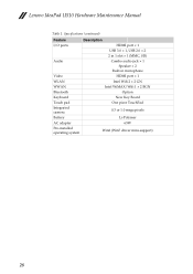
Specifications (continued) Feature I/O ports Audio Video WLAN WWAN Bluetooth Keyboard Touch pad Integrated camera Battery AC adapter Pre-installed operating system Description HDMI port × 1 USB 3.0 × 1, USB 2.0 × 2 2 in 1 slot × 1 (MMC, SD) Combo audio jack × 1 Speaker × 2 Built-in microphone HDMI port × 1 Intel Wifi 2 × 2 GN Intel WiMAX/Wifi 1 × 2 BGN Option New Key Board One piece TouchPad 0.3 or 1.0 mega pixels Li-Polymer 65W Win8 (Win7 driver mini-support) 28 Lenovo IdeaPad U510 Hardware Maintenance Manual Table 1.
Specifications (continued) Feature I/O ports Audio Video WLAN WWAN Bluetooth Keyboard Touch pad Integrated camera Battery AC adapter Pre-installed operating system Description HDMI port × 1 USB 3.0 × 1, USB 2.0 × 2 2 in 1 slot × 1 (MMC, SD) Combo audio jack × 1 Speaker × 2 Built-in microphone HDMI port × 1 Intel Wifi 2 × 2 GN Intel WiMAX/Wifi 1 × 2 BGN Option New Key Board One piece TouchPad 0.3 or 1.0 mega pixels Li-Polymer 65W Win8 (Win7 driver mini-support) 28 Lenovo IdeaPad U510 Hardware Maintenance Manual Table 1.
Hardware Maintenance Manual
Page 37
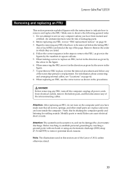
...3. Verify this by the numbers in this section are listed at the top of damaging parts. 2. Any of such FRUs are of the Lenovo U410, unless otherwise stated. 33 To put the new FRU in the figure. 6. Do not attempt to remove potential shock reasons. When...system board is sensitive to remove the FRU, as shown in the figure. 7. Note: The illustrations used in square callouts. 5. Follow the correct sequence in the steps to , and can cause electrical short circuits. DANGER Before removing any FRU, review "FRU replacement notices" on page 64. 8. Lenovo IdeaPad U510 ...
...3. Verify this by the numbers in this section are listed at the top of damaging parts. 2. Any of such FRUs are of the Lenovo U410, unless otherwise stated. 33 To put the new FRU in the figure. 6. Do not attempt to remove potential shock reasons. When...system board is sensitive to remove the FRU, as shown in the figure. 7. Note: The illustrations used in square callouts. 5. Follow the correct sequence in the steps to , and can cause electrical short circuits. DANGER Before removing any FRU, review "FRU replacement notices" on page 64. 8. Lenovo IdeaPad U510 ...

Hardware Maintenance Manual
Page 41
...the direction shown by arrows a , then remove four screws b. c b i h ed j f g When installing: Make sure that all the connectors are attached firmly. Lenovo IdeaPad U510 Figure 2. b b a a b a b a Step a Screw (quantity) M2.5 × 10 mm, flat-head, nylok-coated (4) Color Black Torque 2.5 kgfcm... speakers cable connector in the direction shown by arrow j , disconnect power board connector in the direction shown by arrows b c , system indicator board connector in the direction shown by arrows d e , USB board connector in the direction shown by arrows f g , touchpad connector in ...
...the direction shown by arrows a , then remove four screws b. c b i h ed j f g When installing: Make sure that all the connectors are attached firmly. Lenovo IdeaPad U510 Figure 2. b b a a b a b a Step a Screw (quantity) M2.5 × 10 mm, flat-head, nylok-coated (4) Color Black Torque 2.5 kgfcm... speakers cable connector in the direction shown by arrow j , disconnect power board connector in the direction shown by arrows b c , system indicator board connector in the direction shown by arrows d e , USB board connector in the direction shown by arrows f g , touchpad connector in ...

Hardware Maintenance Manual
Page 53
Remove screw b and six screws c. d When installing: Make sure that the fan connector is attached firmly to damage the connector. Lenovo IdeaPad U510 1090 Fan assembly and Heat Sink assembly For access, remove this FRU: • "1010 Keyboard" on page 34 • "1020 Battery pack" on page 36..." on page 41 • "1050 Optical drive" on page 43 • "1080 Low-frame module" on page 47 Figure 9. Be careful not to the system board. 49 cc cc b cc a Step a Screw (quantity) Color M2.5 × 4 mm, flat-head, nylok-coated (1) Black M2.0 × 3.0 mm, flat-head, nylok-coated Silver ...
Remove screw b and six screws c. d When installing: Make sure that the fan connector is attached firmly to damage the connector. Lenovo IdeaPad U510 1090 Fan assembly and Heat Sink assembly For access, remove this FRU: • "1010 Keyboard" on page 34 • "1020 Battery pack" on page 36..." on page 41 • "1050 Optical drive" on page 43 • "1080 Low-frame module" on page 47 Figure 9. Be careful not to the system board. 49 cc cc b cc a Step a Screw (quantity) Color M2.5 × 4 mm, flat-head, nylok-coated (1) Black M2.0 × 3.0 mm, flat-head, nylok-coated Silver ...
Hardware Maintenance Manual
Page 55
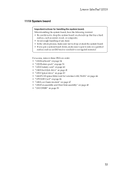
... whole process, make sure not to drop or stack the system board. • If you put a system board down, make sure to put it only on page 50 51 Lenovo IdeaPad U510 1110 System board Important notices for handling the system board: When handling the system board, bear the following in order: • "1010 Keyboard" on page 34...
... whole process, make sure not to drop or stack the system board. • If you put a system board down, make sure to put it only on page 50 51 Lenovo IdeaPad U510 1110 System board Important notices for handling the system board: When handling the system board, bear the following in order: • "1010 Keyboard" on page 34...

Hardware Maintenance Manual
Page 56
a b When installing: Make sure that all the connectors are attached firmly. 52 Removal steps of system board (continued) Disconnect the LCD connector in the direction shown by arrow a , unplug Bluetooth connector in the direction shown by arrow b . Lenovo IdeaPad U510 Hardware Maintenance Manual Figure 11.
a b When installing: Make sure that all the connectors are attached firmly. 52 Removal steps of system board (continued) Disconnect the LCD connector in the direction shown by arrow a , unplug Bluetooth connector in the direction shown by arrow b . Lenovo IdeaPad U510 Hardware Maintenance Manual Figure 11.

Hardware Maintenance Manual
Page 57
c d c b a When installing: When attaching the system board to the holes on the base cover as shown. Improper placement of the combo audio jack, USB, HDMI, RJ-45 ports as shown in the direction shown by arrow c. Removal steps of system board (continued) Remove the system board in , and make sure that they are attached to the base cover, adjust the placement of those jacks might cause a damage. 53 Lenovo IdeaPad U510 Figure 11.
c d c b a When installing: When attaching the system board to the holes on the base cover as shown. Improper placement of the combo audio jack, USB, HDMI, RJ-45 ports as shown in the direction shown by arrow c. Removal steps of system board (continued) Remove the system board in , and make sure that they are attached to the base cover, adjust the placement of those jacks might cause a damage. 53 Lenovo IdeaPad U510 Figure 11.

Hardware Maintenance Manual
Page 58
... a Screw (quantity) M2.5 × 4 mm, flat-head, nylok-coated Color Black Torque 2.5 kgfcm When installing: • Route the antenna cables along the cable guides. 54 Lenovo IdeaPad U510 Hardware Maintenance Manual 1120 LCD unit For access, remove these FRUs in order: • "1010 Keyboard" on page 34 • "1020 Battery pack" on page...-frame module" on page 47 • "1090 Fan assembly and Heat Sink assembly" on page 49 • "1100 DIMM" on page 50 • "1110 System board" on page 51 Figure 12.
... a Screw (quantity) M2.5 × 4 mm, flat-head, nylok-coated Color Black Torque 2.5 kgfcm When installing: • Route the antenna cables along the cable guides. 54 Lenovo IdeaPad U510 Hardware Maintenance Manual 1120 LCD unit For access, remove these FRUs in order: • "1010 Keyboard" on page 34 • "1020 Battery pack" on page...-frame module" on page 47 • "1090 Fan assembly and Heat Sink assembly" on page 49 • "1100 DIMM" on page 50 • "1110 System board" on page 51 Figure 12.

Hardware Maintenance Manual
Page 60
... speakers Remove screw a, and then remove the USB board in order: • "1010 Keyboard" on page 34 • "1020 Battery pack" on page 36 • "... as shown , and make sure that both of the jacks might cause a damage. 56 Lenovo IdeaPad U510 Hardware Maintenance Manual 1130 Base cover, USB board, bluetooth card, power board and speakers For access, remove these FRUs in the direction shown by arrow b. Improper placement ...) a M2.5 × 4 mm, flat-head, nylok-coated (1) Color Black Torque 2.5 kgfcm When installing: When attaching the USB board to the holes on page 54 Figure 13.
... speakers Remove screw a, and then remove the USB board in order: • "1010 Keyboard" on page 34 • "1020 Battery pack" on page 36 • "... as shown , and make sure that both of the jacks might cause a damage. 56 Lenovo IdeaPad U510 Hardware Maintenance Manual 1130 Base cover, USB board, bluetooth card, power board and speakers For access, remove these FRUs in the direction shown by arrow b. Improper placement ...) a M2.5 × 4 mm, flat-head, nylok-coated (1) Color Black Torque 2.5 kgfcm When installing: When attaching the USB board to the holes on page 54 Figure 13.

Hardware Maintenance Manual
Page 61
a b Step Screw (quantity) a M2.5 × 4 mm, flat-head, nylok-coated (1) Color Black Torque 2.5 kgfcm 57 a Remove the screw a to lift the power board in the direction shown by arrow b. Base cover, USB board, bluetooth card, power board and speakers (continued) Remove the bluetooth card in the direction shown by arrow a . Lenovo IdeaPad U510 Figure 13.
a b Step Screw (quantity) a M2.5 × 4 mm, flat-head, nylok-coated (1) Color Black Torque 2.5 kgfcm 57 a Remove the screw a to lift the power board in the direction shown by arrow b. Base cover, USB board, bluetooth card, power board and speakers (continued) Remove the bluetooth card in the direction shown by arrow a . Lenovo IdeaPad U510 Figure 13.

Hardware Maintenance Manual
Page 62
Base cover, USB board, bluetooth card, power board and speakers (continued) Remove four screws a , and then remove the speakers in the direction shown by arrows b . a a b aa b Step Screw (quantity) a M2.5 × 2.0 mm, flat-head, nylok-coated (4) Color Black Torque 2.5 kgfcm 58 Lenovo IdeaPad U510 Hardware Maintenance Manual Figure 13.
Base cover, USB board, bluetooth card, power board and speakers (continued) Remove four screws a , and then remove the speakers in the direction shown by arrows b . a a b aa b Step Screw (quantity) a M2.5 × 2.0 mm, flat-head, nylok-coated (4) Color Black Torque 2.5 kgfcm 58 Lenovo IdeaPad U510 Hardware Maintenance Manual Figure 13.

Hardware Maintenance Manual
Page 64
...; "1090 Fan assembly and Heat Sink assembly" on page 49 • "1100 DIMM" on page 50 • "1110 System board" on page 51 • "1120 LCD unit" on page 54 Figure 14. a a a a 60 Lenovo IdeaPad U510 Hardware Maintenance Manual 1140 LCD front bezel For access, remove these FRUs in the direction shown by arrows a.
...; "1090 Fan assembly and Heat Sink assembly" on page 49 • "1100 DIMM" on page 50 • "1110 System board" on page 51 • "1120 LCD unit" on page 54 Figure 14. a a a a 60 Lenovo IdeaPad U510 Hardware Maintenance Manual 1140 LCD front bezel For access, remove these FRUs in the direction shown by arrows a.

Hardware Maintenance Manual
Page 65
LCD panel, LCD cable and hinges Remove screws a. Lenovo IdeaPad U510 1150 LCD panel, LCD cable and hinges For access, remove these FRUs in order: • "1010 Keyboard" on page 34 • "1020 Battery pack" on ... and Heat Sink assembly" on page 49 • "1100 DIMM" on page 50 • "1110 System board" on page 51 • "1120 LCD unit" on page 54 • "1130 Base cover, USB board, bluetooth card, power board and speakers" on page 56 • "1140 LCD front bezel" on page 60 Figure 15. a a a a Step...
LCD panel, LCD cable and hinges Remove screws a. Lenovo IdeaPad U510 1150 LCD panel, LCD cable and hinges For access, remove these FRUs in order: • "1010 Keyboard" on page 34 • "1020 Battery pack" on ... and Heat Sink assembly" on page 49 • "1100 DIMM" on page 50 • "1110 System board" on page 51 • "1120 LCD unit" on page 54 • "1130 Base cover, USB board, bluetooth card, power board and speakers" on page 56 • "1140 LCD front bezel" on page 60 Figure 15. a a a a Step...

Hardware Maintenance Manual
Page 67
...Heat Sink assembly" on page 49 • "1100 DIMM" on page 50 • "1110 System board" on page 51 • "1120 LCD unit" on page 54 • "1130 Base cover, USB board, bluetooth card, power board and speakers" on page 56 • "1140 LCD front bezel" on page 60 • "1150... LCD panel, LCD cable and hinges" on the top center of integrated camera Note: The integrated camera is attached firmly. 63 Removal steps of the LCD cover. Lenovo IdeaPad U510 1160 Integrated...
...Heat Sink assembly" on page 49 • "1100 DIMM" on page 50 • "1110 System board" on page 51 • "1120 LCD unit" on page 54 • "1130 Base cover, USB board, bluetooth card, power board and speakers" on page 56 • "1140 LCD front bezel" on page 60 • "1150... LCD panel, LCD cable and hinges" on the top center of integrated camera Note: The integrated camera is attached firmly. 63 Removal steps of the LCD cover. Lenovo IdeaPad U510 1160 Integrated...


