
Hardware Maintenance Manual
Page 3
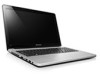
...General checkout 19 What to do first 20 Power system checkout 21 Checking the AC adapter 21 Checking operational charging 21 Checking the battery pack 22 Related service information 23 Restoring the factory contents by using Recovery Disc Set 23 Start Recovery Disc (one disc 23 ... (standby) state 25 Shutting down the computer 26 Lenovo IdeaPad U510 27 Specifications 27 Status indicators 29 Fn key combinations 31 Hotkeys 31 FRU replacement notices 32 Screw notices 32 Removing and replacing an FRU 33 1010 Keyboard 34 1020 Battery pack 36 1030 Dummy card 40 1040 Hard disk ...
...General checkout 19 What to do first 20 Power system checkout 21 Checking the AC adapter 21 Checking operational charging 21 Checking the battery pack 22 Related service information 23 Restoring the factory contents by using Recovery Disc Set 23 Start Recovery Disc (one disc 23 ... (standby) state 25 Shutting down the computer 26 Lenovo IdeaPad U510 27 Specifications 27 Status indicators 29 Fn key combinations 31 Hotkeys 31 FRU replacement notices 32 Screw notices 32 Removing and replacing an FRU 33 1010 Keyboard 34 1020 Battery pack 36 1030 Dummy card 40 1040 Hard disk ...

Hardware Maintenance Manual
Page 9
...identifying potential unsafe conditions. Check for : a. Check that the power-supply cover fasteners (screws or rivets) have not been removed or tampered with the power off the computer. Safety information Safety inspection guide The purpose of this inspection guide. As each ...frame ground. Disconnect the power cord. 3. Begin the checks with . 5 Checklist: 1. Check for any non-Lenovo alterations. 7. b. Check inside the unit for cracked or bulging batteries. 5. Check exterior covers for damage (loose, broken, or sharp edges). 2. Consider these conditions and the ...
...identifying potential unsafe conditions. Check for : a. Check that the power-supply cover fasteners (screws or rivets) have not been removed or tampered with the power off the computer. Safety information Safety inspection guide The purpose of this inspection guide. As each ...frame ground. Disconnect the power cord. 3. Begin the checks with . 5 Checklist: 1. Check for any non-Lenovo alterations. 7. b. Check inside the unit for cracked or bulging batteries. 5. Check exterior covers for damage (loose, broken, or sharp edges). 2. Consider these conditions and the ...

Hardware Maintenance Manual
Page 25
... the system board. • If the problem persists, go to "Lenovo IdeaPad U510" on , check the power cord of the AC adapter cable. Disconnect the AC adapter and install the charged battery pack. 7. Turn off the computer. 2. Note: Noise from the computer. 2. Remove the battery pack. 3. If the voltage is acceptable, do the following figure: Pin...
... the system board. • If the problem persists, go to "Lenovo IdeaPad U510" on , check the power cord of the AC adapter cable. Disconnect the AC adapter and install the charged battery pack. 7. Turn off the computer. 2. Note: Noise from the computer. 2. Remove the battery pack. 3. If the voltage is acceptable, do the following figure: Pin...

Hardware Maintenance Manual
Page 26
... charged, go to the Power Meter icon in the icon tray of battery power remaining is displayed. To get detailed information about the battery, double-click the Power Meter icon. Remove it ), and the percentage of the Windows® taskbar and wait for...battery pack from being overcharged or from the computer and leave it at room temperature for a moment (but do not click it from having a shortened life. Then reinstall the battery pack. Lenovo IdeaPad U510 Hardware Maintenance Manual Perform operational charging. If the charge indicator still does not light on , remove the battery...
... charged, go to the Power Meter icon in the icon tray of battery power remaining is displayed. To get detailed information about the battery, double-click the Power Meter icon. Remove it ), and the percentage of the Windows® taskbar and wait for...battery pack from being overcharged or from the computer and leave it at room temperature for a moment (but do not click it from having a shortened life. Then reinstall the battery pack. Lenovo IdeaPad U510 Hardware Maintenance Manual Perform operational charging. If the charge indicator still does not light on , remove the battery...
Hardware Maintenance Manual
Page 37
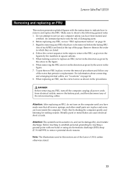
... to service any computer unless you have made sure that all power cords from electrical outlets, remove the battery pack, and then disconnect any FRU, review "FRU replacement notices" on page 64. 8. Remove them in the order in the figure. 6. When turning a screw to replace an FRU,...computer gently and listening for rattling sounds. Attention: The system board is sensitive to, and can cause electrical short circuits. Lenovo IdeaPad U510 Removing and replacing an FRU This section presents exploded figures with one hand or using an electrostatic discharge (ESD) strap (P/N 6405959) to...
... to service any computer unless you have made sure that all power cords from electrical outlets, remove the battery pack, and then disconnect any FRU, review "FRU replacement notices" on page 64. 8. Remove them in the order in the figure. 6. When turning a screw to replace an FRU,...computer gently and listening for rattling sounds. Attention: The system board is sensitive to, and can cause electrical short circuits. Lenovo IdeaPad U510 Removing and replacing an FRU This section presents exploded figures with one hand or using an electrostatic discharge (ESD) strap (P/N 6405959) to...

Hardware Maintenance Manual
Page 40
Lenovo IdeaPad U510 Hardware Maintenance Manual 1020 Battery pack For access, remove this FRU: • "1010 Keyboard" on page 34 DANGER • Only use the battery specified in the parts list for your computer. Figure 2. a a aa a 36 Removal steps of battery pack Remove five screws a . Any other battery could ignite or explode. • Make sure the battery has been disconnected already before replacing any devices.
Lenovo IdeaPad U510 Hardware Maintenance Manual 1020 Battery pack For access, remove this FRU: • "1010 Keyboard" on page 34 DANGER • Only use the battery specified in the parts list for your computer. Figure 2. a a aa a 36 Removal steps of battery pack Remove five screws a . Any other battery could ignite or explode. • Make sure the battery has been disconnected already before replacing any devices.

Hardware Maintenance Manual
Page 41
Removal steps of battery pack (continued) Unplug the speakers cable connector in the direction shown by arrow j , disconnect power board connector in the direction shown by arrows b c , system indicator ... mm, flat-head, nylok-coated (4) Color Black Torque 2.5 kgfcm 37 Open four rubber foot pads with a screw driver in the direction shown by arrows a , then remove four screws b. c b i h ed j f g When installing: Make sure that all the connectors are attached firmly. Lenovo IdeaPad U510 Figure 2.
Removal steps of battery pack (continued) Unplug the speakers cable connector in the direction shown by arrow j , disconnect power board connector in the direction shown by arrows b c , system indicator ... mm, flat-head, nylok-coated (4) Color Black Torque 2.5 kgfcm 37 Open four rubber foot pads with a screw driver in the direction shown by arrows a , then remove four screws b. c b i h ed j f g When installing: Make sure that all the connectors are attached firmly. Lenovo IdeaPad U510 Figure 2.

Hardware Maintenance Manual
Page 42
Removal steps of battery pack (continued) Open the back cover along the device frame with a flat blade in the direction shown by arrows and then lift the back cover in the direction shown by arrow c. e e d e Step c Screw (quantity) M2.5 × 6 mm, flat-head, nylokcoated (3) Color Silver Torque 2.5 kgfcm 38 c Unplug the battery connector in the direction shown by arrow d first, then remove three screws e . Lenovo IdeaPad U510 Hardware Maintenance Manual Figure 2.
Removal steps of battery pack (continued) Open the back cover along the device frame with a flat blade in the direction shown by arrows and then lift the back cover in the direction shown by arrow c. e e d e Step c Screw (quantity) M2.5 × 6 mm, flat-head, nylokcoated (3) Color Silver Torque 2.5 kgfcm 38 c Unplug the battery connector in the direction shown by arrow d first, then remove three screws e . Lenovo IdeaPad U510 Hardware Maintenance Manual Figure 2.

Hardware Maintenance Manual
Page 43
f When installing: • Separate the antenna from other cables. Put them in the direction shown by arrow f . Removal steps of battery pack (continued) Remove the battery in different tracks to improve signal reception. • Connect the battery last. 39 Lenovo IdeaPad U510 Figure 2.
f When installing: • Separate the antenna from other cables. Put them in the direction shown by arrow f . Removal steps of battery pack (continued) Remove the battery in different tracks to improve signal reception. • Connect the battery last. 39 Lenovo IdeaPad U510 Figure 2.

Hardware Maintenance Manual
Page 45
... the information on page 36 Attention: • Do not drop the hard disk drive or apply any physical shock to it if possible. • Never remove the drive while the system is operating or is sensitive to physical shock. a a a a b Step a Screw (quantity) Color M2.5 × 6 mm, ... can cause damages and permanent loss of hard disk drive Remove the frame fixing screws a . The hard disk drive is in the direction shown by arrow b. Lenovo IdeaPad U510 1040 Hard disk drive For access, remove this FRU: • "1010 Keyboard" on page 34 • "1020 Battery pack" on it . Figure 4.
... the information on page 36 Attention: • Do not drop the hard disk drive or apply any physical shock to it if possible. • Never remove the drive while the system is operating or is sensitive to physical shock. a a a a b Step a Screw (quantity) Color M2.5 × 6 mm, ... can cause damages and permanent loss of hard disk drive Remove the frame fixing screws a . The hard disk drive is in the direction shown by arrow b. Lenovo IdeaPad U510 1040 Hard disk drive For access, remove this FRU: • "1010 Keyboard" on page 34 • "1020 Battery pack" on it . Figure 4.

Hardware Maintenance Manual
Page 47
a 43 Removal steps of optical drive Pull the optical drive out in order: • "1010 Keyboard" on page 34 • "1020 Battery pack" on page 36 • "1030 Dummy card" on page 40 Figure 5. Lenovo IdeaPad U510 1050 Optical drive For access, remove these FRUs in the direction shown by arrow a.
a 43 Removal steps of optical drive Pull the optical drive out in order: • "1010 Keyboard" on page 34 • "1020 Battery pack" on page 36 • "1030 Dummy card" on page 40 Figure 5. Lenovo IdeaPad U510 1050 Optical drive For access, remove these FRUs in the direction shown by arrow a.

Hardware Maintenance Manual
Page 48
... a. wireless LAN card in some models may have 3 cables in step a. Removal steps of PCI Express Mini Card for wireless LAN/WAN For access, remove this FRU: • "1010 Keyboard" on page 34 • "1020 Battery pack" on page 36 Figure 6. Lenovo IdeaPad U510 Hardware Maintenance Manual 1060 PCI Express Mini Card for wireless LAN/WAN...
... a. wireless LAN card in some models may have 3 cables in step a. Removal steps of PCI Express Mini Card for wireless LAN/WAN For access, remove this FRU: • "1010 Keyboard" on page 34 • "1020 Battery pack" on page 36 Figure 6. Lenovo IdeaPad U510 Hardware Maintenance Manual 1060 PCI Express Mini Card for wireless LAN/WAN...

Hardware Maintenance Manual
Page 50
b Step a Screw (quantity) M2.0 × 3.0 mm, flat-head, nylok-coated (1) Color Black Torque 1.8 kgfcm 46 Lenovo IdeaPad U510 Hardware Maintenance Manual 1070 SSD Card For access, remove these FRUs in the direction shown by arrow b. Removal steps of SSD Card Remove the screw a. a Remove the card in order: • "1020 Battery pack" on page 36 Figure 7.
b Step a Screw (quantity) M2.0 × 3.0 mm, flat-head, nylok-coated (1) Color Black Torque 1.8 kgfcm 46 Lenovo IdeaPad U510 Hardware Maintenance Manual 1070 SSD Card For access, remove these FRUs in the direction shown by arrow b. Removal steps of SSD Card Remove the screw a. a Remove the card in order: • "1020 Battery pack" on page 36 Figure 7.

Hardware Maintenance Manual
Page 51
a a a a a a Step a Screw (quantity) Color M2.5 x 6.0 mm, flat-head, nylok-coated Silver (1) Torque 2.5 kgfcm Lift the power assembly in order: • "1010 Keyboard" on page 34 • "1020 Battery pack" on page 36 • "1040 Hard disk drive" on page 41 • "1050 Optical drive" on page 43 Figure 8. Lenovo IdeaPad U510 1080 Low-frame module For access, remove these FRUs in the direction shown by arrow b. Removal steps of low-frame module Remove six screws a. b 47
a a a a a a Step a Screw (quantity) Color M2.5 x 6.0 mm, flat-head, nylok-coated Silver (1) Torque 2.5 kgfcm Lift the power assembly in order: • "1010 Keyboard" on page 34 • "1020 Battery pack" on page 36 • "1040 Hard disk drive" on page 41 • "1050 Optical drive" on page 43 Figure 8. Lenovo IdeaPad U510 1080 Low-frame module For access, remove these FRUs in the direction shown by arrow b. Removal steps of low-frame module Remove six screws a. b 47

Hardware Maintenance Manual
Page 53
Be careful not to the system board. 49 Lenovo IdeaPad U510 1090 Fan assembly and Heat Sink assembly For access, remove this FRU: • "1010 Keyboard" on page 34 • "1020 Battery pack" on page 36 • "1040 Hard disk drive" on page 41 • "1050 Optical drive" on page 43 • "1080 Low...-frame module" on page 47 Figure 9. Removal steps of fan assembly and heat sink assembly Unplug the fan connector...
Be careful not to the system board. 49 Lenovo IdeaPad U510 1090 Fan assembly and Heat Sink assembly For access, remove this FRU: • "1010 Keyboard" on page 34 • "1020 Battery pack" on page 36 • "1040 Hard disk drive" on page 41 • "1050 Optical drive" on page 43 • "1080 Low...-frame module" on page 47 Figure 9. Removal steps of fan assembly and heat sink assembly Unplug the fan connector...

Hardware Maintenance Manual
Page 54
... of DIMM Release the two latches on page 47 Figure 10. Lenovo IdeaPad U510 Hardware Maintenance Manual 1100 DIMM For access, remove these FRUs in order: • "1010 Keyboard" on page 34 • "1020 Battery pack" on page 36 • "1080 Low-frame module" on both edges of the DIMM into the place. Push the...
... of DIMM Release the two latches on page 47 Figure 10. Lenovo IdeaPad U510 Hardware Maintenance Manual 1100 DIMM For access, remove these FRUs in order: • "1010 Keyboard" on page 34 • "1020 Battery pack" on page 36 • "1080 Low-frame module" on both edges of the DIMM into the place. Push the...
Hardware Maintenance Manual
Page 55
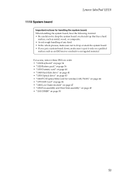
Lenovo IdeaPad U510 1110 System board Important notices for wireless LAN/WAN" on page 44 • "1070 SSD Card" on page 46 • "1080 Low-frame module" on ... page 49 • "1100 DIMM" on a padded surface such as an ESD mat or conductive corrugated material. For access, remove these FRUs in order: • "1010 Keyboard" on page 34 • "1020 Battery pack" on page 36 • "1030 Dummy card" on page 40 • "1040 Hard disk drive" on page 41...
Lenovo IdeaPad U510 1110 System board Important notices for wireless LAN/WAN" on page 44 • "1070 SSD Card" on page 46 • "1080 Low-frame module" on ... page 49 • "1100 DIMM" on a padded surface such as an ESD mat or conductive corrugated material. For access, remove these FRUs in order: • "1010 Keyboard" on page 34 • "1020 Battery pack" on page 36 • "1030 Dummy card" on page 40 • "1040 Hard disk drive" on page 41...

Hardware Maintenance Manual
Page 58
Lenovo IdeaPad U510 Hardware Maintenance Manual 1120 LCD unit For access, remove these FRUs in order: • "1010 Keyboard" on page 34 • "1020 Battery pack" on page 36 • "1030 Dummy card" on page 40 • "1040 Hard disk drive" on page 41 • "1050 Optical drive" ... antenna cables when you route the cables, make sure that they are not subjected to any tension. As you attach the LCD assembly. Removal steps of LCD unit Remove four screws a. aa aa Step a Screw (quantity) M2.5 × 4 mm, flat-head, nylok-coated Color Black Torque 2.5 kgfcm When installing: •...
Lenovo IdeaPad U510 Hardware Maintenance Manual 1120 LCD unit For access, remove these FRUs in order: • "1010 Keyboard" on page 34 • "1020 Battery pack" on page 36 • "1030 Dummy card" on page 40 • "1040 Hard disk drive" on page 41 • "1050 Optical drive" ... antenna cables when you route the cables, make sure that they are not subjected to any tension. As you attach the LCD assembly. Removal steps of LCD unit Remove four screws a. aa aa Step a Screw (quantity) M2.5 × 4 mm, flat-head, nylok-coated Color Black Torque 2.5 kgfcm When installing: •...

Hardware Maintenance Manual
Page 60
... the holes on page 54 Figure 13. Base cover, USB board, bluetooth card, power board and speakers Remove screw a, and then remove the USB board in order: • "1010 Keyboard" on page 34 • "1020 Battery pack" on page 36 • "1030 Dummy card" on page 40 • "1040 Hard disk ... • "1100 DIMM" on page 50 • "1110 System board" on page 51 • "1120 LCD unit" on the base cover as shown. Lenovo IdeaPad U510 Hardware Maintenance Manual 1130 Base cover, USB board, bluetooth card, power board and speakers For access, remove these FRUs in the direction shown by arrow b.
... the holes on page 54 Figure 13. Base cover, USB board, bluetooth card, power board and speakers Remove screw a, and then remove the USB board in order: • "1010 Keyboard" on page 34 • "1020 Battery pack" on page 36 • "1030 Dummy card" on page 40 • "1040 Hard disk ... • "1100 DIMM" on page 50 • "1110 System board" on page 51 • "1120 LCD unit" on the base cover as shown. Lenovo IdeaPad U510 Hardware Maintenance Manual 1130 Base cover, USB board, bluetooth card, power board and speakers For access, remove these FRUs in the direction shown by arrow b.

Hardware Maintenance Manual
Page 64
a a a a 60 Lenovo IdeaPad U510 Hardware Maintenance Manual 1140 LCD front bezel For access, remove these FRUs in the direction shown by arrows a. Removal steps of LCD front bezel Remove the LCD front bezel in order: • "1010 Keyboard" on page 34 • "1020 Battery pack" on page 36 • "1030 Dummy card" on page 40 • "1040 Hard...
a a a a 60 Lenovo IdeaPad U510 Hardware Maintenance Manual 1140 LCD front bezel For access, remove these FRUs in the direction shown by arrows a. Removal steps of LCD front bezel Remove the LCD front bezel in order: • "1010 Keyboard" on page 34 • "1020 Battery pack" on page 36 • "1030 Dummy card" on page 40 • "1040 Hard...


