Hardware Maintenance Manual for K220
Page 2
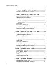
... changing the startup device sequence 26 Exiting from the Setup Utility program 21 Chapter 6. Symptom-to-FRU Index 34 Hard disk drive boot error 34 Power Supply Problems 35 Beep symptoms 36 POST error codes 37 Undetermined problems 39 Chapter 9. Replacing hardware 40 Removing the computer cover 40 Removing and replacing the...
... changing the startup device sequence 26 Exiting from the Setup Utility program 21 Chapter 6. Symptom-to-FRU Index 34 Hard disk drive boot error 34 Power Supply Problems 35 Beep symptoms 36 POST error codes 37 Undetermined problems 39 Chapter 9. Replacing hardware 40 Removing the computer cover 40 Removing and replacing the...
Hardware Maintenance Manual for K220
Page 3
... Additional Service Information (Type G33 57 Power management 57 Automatic configuration and power interface (ACPI) BIOS 57 Automatic Power-On features 57 Chapter 11. Additional Service Information (Type G43 58 Power management 58 Automatic configuration and power interface (ACPI) BIOS 58 Power Management features 58 Chapter 12. Contents Replacing the power supply 43 Replacing the heat sink assembly...
... Additional Service Information (Type G33 57 Power management 57 Automatic configuration and power interface (ACPI) BIOS 57 Automatic Power-On features 57 Chapter 11. Additional Service Information (Type G43 58 Power management 58 Automatic configuration and power interface (ACPI) BIOS 58 Power Management features 58 Chapter 12. Contents Replacing the power supply 43 Replacing the heat sink assembly...

Hardware Maintenance Manual for K220
Page 8
...the wall box in the installation and configuration procedures. Some hand tools have , near power supplies - Chapter 2. Observe the following rules when working in any safety device that supplies power to the machine and to your eyes. •• After service, reinstall all ...drilling soldering, cutting wire, attaching springs, using solvents, or working on the machine, unplug the power cord. To avoid personal injury or equipment damage, disconnect the attached power cords, telecommunication systems, networks, and modems before you when working with a soft material that has...
...the wall box in the installation and configuration procedures. Some hand tools have , near power supplies - Chapter 2. Observe the following rules when working in any safety device that supplies power to the machine and to your eyes. •• After service, reinstall all ...drilling soldering, cutting wire, attaching springs, using solvents, or working on the machine, unplug the power cord. To avoid personal injury or equipment damage, disconnect the attached power cords, telecommunication systems, networks, and modems before you when working with a soft material that has...
Hardware Maintenance Manual for K220
Page 9
...Stand on suitable rubber mats (obtained locally, if necessary) to insulate you may prevent a current from their normal operating places in a machine: - Power supply units - Blowers and fans - do not become a victim yourself. - keep the other hand in your pocket or behind your electrical hand tools for... safe operational condition. •• Do not use the approved probe leads and accessories for that another person to switch off the power, if necessary. - By observing the above rule, you from a circuit. Observe the special safety precautions when you . The surface is...
...Stand on suitable rubber mats (obtained locally, if necessary) to insulate you may prevent a current from their normal operating places in a machine: - Power supply units - Blowers and fans - do not become a victim yourself. - keep the other hand in your pocket or behind your electrical hand tools for... safe operational condition. •• Do not use the approved probe leads and accessories for that another person to switch off the power, if necessary. - By observing the above rule, you from a circuit. Observe the special safety precautions when you . The surface is...
Hardware Maintenance Manual for K220
Page 10
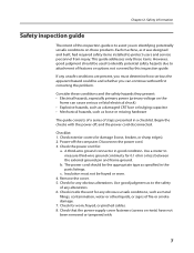
...power-supply cover fasteners (screws or rivets) have not been removed or tampered with the power off the computer. Begin the checks with . 7 Disconnect the power cord. 3. Chapter 2. Check exterior covers for worn, frayed, or pinched cables. 8. Power-off , and the power cord disconnected. Check the power...the parts listings. Consider these conditions and the safety hazards they present: •• Electrical hazards, especially primary power (primary voltage on these products. Insulation must determine how serious the apparent hazard could be frayed or worn. 4. ...
...power-supply cover fasteners (screws or rivets) have not been removed or tampered with the power off the computer. Begin the checks with . 7 Disconnect the power cord. 3. Chapter 2. Check exterior covers for worn, frayed, or pinched cables. 8. Power-off , and the power cord disconnected. Check the power...the parts listings. Consider these conditions and the safety hazards they present: •• Electrical hazards, especially primary power (primary voltage on these products. Insulation must determine how serious the apparent hazard could be frayed or worn. 4. ...
Hardware Maintenance Manual for K220
Page 14
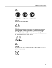
The device also might have more than one power cord. Chapter 2. CAUTION: The power control button on the device and the power switch on top of rack-mounted devices. 11 To remove all electrical current from the device, ensure that all power cords are disconnected from the power source. 2 1 CAUTION: Do not place any object weighing more than 82 kg (180 lbs.) on the power supply do not turn off the electrical current supplied to the device. Safety information CAUTION: Use safe practices when lifting.
The device also might have more than one power cord. Chapter 2. CAUTION: The power control button on the device and the power switch on top of rack-mounted devices. 11 To remove all electrical current from the device, ensure that all power cords are disconnected from the power source. 2 1 CAUTION: Do not place any object weighing more than 82 kg (180 lbs.) on the power supply do not turn off the electrical current supplied to the device. Safety information CAUTION: Use safe practices when lifting.

Hardware Maintenance Manual for K220
Page 16
...: 1. Be extremely careful during write operations such as copying, saving, or formatting. For an explanation of these messages, refer to the information supplied with that the latest level of BIOS is found by POST. • To enable beep, memory count, and checkpoint code display when a ... if a problem or conflict is installed on all display controls to help determine the cause of the system board. Power-off the computer and all cables and power cords. 3. A down-level BIOS might have been rearranged or the drive startup sequence changed. Check all external devices...
...: 1. Be extremely careful during write operations such as copying, saving, or formatting. For an explanation of these messages, refer to the information supplied with that the latest level of BIOS is found by POST. • To enable beep, memory count, and checkpoint code display when a ... if a problem or conflict is installed on all display controls to help determine the cause of the system board. Power-off the computer and all cables and power cords. 3. A down-level BIOS might have been rearranged or the drive startup sequence changed. Check all external devices...
Hardware Maintenance Manual for K220
Page 38
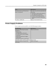
... Check the following procedures. Power Supply Problems If you suspect a power problem, use the following for proper Reseat connectors installation. •• Power Cord •• On/Off Switch connector •• On/Off Switch Power Supply connector •• System Board Power Supply connectors •• Microprocessor(s) connection Check the power cord for Power-on the failing hard disk...
... Check the following procedures. Power Supply Problems If you suspect a power problem, use the following for proper Reseat connectors installation. •• Power Cord •• On/Off Switch connector •• On/Off Switch Power Supply connector •• System Board Power Supply connectors •• Microprocessor(s) connection Check the power cord for Power-on the failing hard disk...
Hardware Maintenance Manual for K220
Page 46
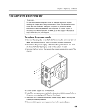
... screws that secure the power supply at http://www.lenovo.com/support. Install the new power supply into the chassis so that was included with those in the Hardware Maintenance Manual (HMM) for the computer. Reconnect the power supply connectors to lay the computer on the system board". 3. To replace the power supply: 1. Disconnect the power supply cables from the system... the Support Web site at the rear of the chassis. 5. To obtain copies of the Safety and Warranty Guide or HMM, go to secure the power supply. Note: Use only the screws provided by Lenovo. 7.
... screws that secure the power supply at http://www.lenovo.com/support. Install the new power supply into the chassis so that was included with those in the Hardware Maintenance Manual (HMM) for the computer. Reconnect the power supply connectors to lay the computer on the system board". 3. To replace the power supply: 1. Disconnect the power supply cables from the system... the Support Web site at the rear of the chassis. 5. To obtain copies of the Safety and Warranty Guide or HMM, go to secure the power supply. Note: Use only the screws provided by Lenovo. 7.

Hardware Maintenance Manual for K220
Page 47
Refer to the Support Web site at http://www.lenovo.com/support. To obtain copies of the Safety and Warranty Guide or HMM, go to the "Completing the installation". Refer to each of grease on ... to the system board. 6. Lift the failing heat sink and fan assembly off the system board. 7. Each drop of the microprocessor. Hardware Maintenance Manual 8. Reconnect a power supply connector to "Removing the computer cover". 2. Locate the heat sink. Remove the computer cover. To replace the heat sink assembly: 1. Remove the four screws securing...
Refer to the Support Web site at http://www.lenovo.com/support. To obtain copies of the Safety and Warranty Guide or HMM, go to the "Completing the installation". Refer to each of grease on ... to the system board. 6. Lift the failing heat sink and fan assembly off the system board. 7. Each drop of the microprocessor. Hardware Maintenance Manual 8. Reconnect a power supply connector to "Removing the computer cover". 2. Locate the heat sink. Remove the computer cover. To replace the heat sink assembly: 1. Remove the four screws securing...
Hardware Maintenance Manual for K220
Page 60
... of certain components of the computer and the setting for Advanced Power Management (APM) BIOS mode is detected on automatically. Automatic Power-On features The Automatic Power-On features within the Power Management menu allow you to enable and disable features that turn on automatically when a ... (ACPI) BIOS Being an ACPI BIOS system, the operating system is allowed to control the power management features of the computer such as the system power supply, processor, hard disk drives, and some monitors. Not all operating systems support ACPI BIOS mode. Additional Service Information...
... of certain components of the computer and the setting for Advanced Power Management (APM) BIOS mode is detected on automatically. Automatic Power-On features The Automatic Power-On features within the Power Management menu allow you to enable and disable features that turn on automatically when a ... (ACPI) BIOS Being an ACPI BIOS system, the operating system is allowed to control the power management features of the computer such as the system power supply, processor, hard disk drives, and some monitors. Not all operating systems support ACPI BIOS mode. Additional Service Information...
Hardware Maintenance Manual for K220
Page 61
... PCI Wake Up: This feature allows PCI cards which support this system. 58 Not all operating systems support ACPI BIOS mode. Automatic configuration and power interface (ACPI) BIOS Being an ACPI BIOS system, the operating system is detected on the internal modem. •• Wake Up On Alarm...: You can be turned on automatically when a ring is allowed to wake this cappability to control the power management features of the computer such as the system power supply, processor, hard disk drives, and some monitors. This can specify a date and time at which the computer will...
... PCI Wake Up: This feature allows PCI cards which support this system. 58 Not all operating systems support ACPI BIOS mode. Automatic configuration and power interface (ACPI) BIOS Being an ACPI BIOS system, the operating system is detected on the internal modem. •• Wake Up On Alarm...: You can be turned on automatically when a ring is allowed to wake this cappability to control the power management features of the computer such as the system power supply, processor, hard disk drives, and some monitors. This can specify a date and time at which the computer will...
Hardware Maintenance Manual for K220
Page 62
... the computer will turn on automatically when a ring is ignored. Automatic configuration and power interface (ACPI) BIOS Being an ACPI BIOS system, the operating system is allowed to control the power management features of the computer such as the system power supply, processor, hard disk drives, and some monitors. 12Chapter 8. Not all operating systems...
... the computer will turn on automatically when a ring is ignored. Automatic configuration and power interface (ACPI) BIOS Being an ACPI BIOS system, the operating system is allowed to control the power management features of the computer such as the system power supply, processor, hard disk drives, and some monitors. 12Chapter 8. Not all operating systems...
IdeaCentre K220 Hardware Replacement Guide
Page 3
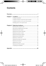
... computer 7 Identifying parts on the system board 9 Chapter 2 Replacing hardware 14 Removing the computer cover 14 Removing and replacing the front bezel 15 Replacing the power supply 17 Replacing the heat sink assembly 18 Replacing a memory module 20 Replacing PCI Express adapter 21 Replacing the hard disk drive 24 Replacing an optical... the system fan assembly 26 Replacing the keyboard 28 Replacing the mouse 29 Replacing the External speaker 30 Completing the installation 30 Appendix 32 31036127 IdeaCentre K_HRG_EN.indd 36 2008.10.20 1:59:47 PM
... computer 7 Identifying parts on the system board 9 Chapter 2 Replacing hardware 14 Removing the computer cover 14 Removing and replacing the front bezel 15 Replacing the power supply 17 Replacing the heat sink assembly 18 Replacing a memory module 20 Replacing PCI Express adapter 21 Replacing the hard disk drive 24 Replacing an optical... the system fan assembly 26 Replacing the keyboard 28 Replacing the mouse 29 Replacing the External speaker 30 Completing the installation 30 Appendix 32 31036127 IdeaCentre K_HRG_EN.indd 36 2008.10.20 1:59:47 PM
IdeaCentre K220 Hardware Replacement Guide
Page 4
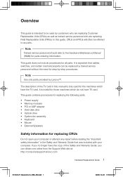
... for step-by Lenovo™. It is invalid for those machines which have the TV card. Note Trained service personnel should refer to be referred to as trained service personnel who are replacing Field Replaceable Units (FRUs). This guide contains procedures for replacing the following parts: • Power supply • Memory ...the Safety and Warranty Guide that cables, switches, and certain mechanical parts can obtain one online from the Support Web site at: http://consumersupport.lenovo.com Hardware Replacement Guide 1 31036127 IdeaCentre K_HRG_EN.indd 1 2008.10.20 1:59:20 PM
... for step-by Lenovo™. It is invalid for those machines which have the TV card. Note Trained service personnel should refer to be referred to as trained service personnel who are replacing Field Replaceable Units (FRUs). This guide contains procedures for replacing the following parts: • Power supply • Memory ...the Safety and Warranty Guide that cables, switches, and certain mechanical parts can obtain one online from the Support Web site at: http://consumersupport.lenovo.com Hardware Replacement Guide 1 31036127 IdeaCentre K_HRG_EN.indd 1 2008.10.20 1:59:20 PM
IdeaCentre K220 Hardware Replacement Guide
Page 8
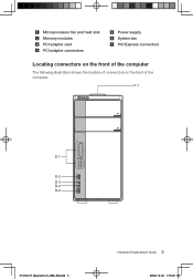
Microprocessor fan and heat sink Memory modules PCI adapter card PCI adapter connectors Power supply System fan PCI Express connectors Locating connectors on the front of the computer The following illustration shows the location of connectors on the front of the computer. F-1 xD CF/I/II/MD MS/Pro/Duo/ProDuo SD/Mini/HC/MiniHC MMC/RS/Plus/Mob D-1 D-2 D-3 D-4 D-2 31036127 IdeaCentre K_HRG_EN.indd 5 Hardware Replacement Guide 5 2008.10.20 1:59:21 PM
Microprocessor fan and heat sink Memory modules PCI adapter card PCI adapter connectors Power supply System fan PCI Express connectors Locating connectors on the front of the computer The following illustration shows the location of connectors on the front of the computer. F-1 xD CF/I/II/MD MS/Pro/Duo/ProDuo SD/Mini/HC/MiniHC MMC/RS/Plus/Mob D-1 D-2 D-3 D-4 D-2 31036127 IdeaCentre K_HRG_EN.indd 5 Hardware Replacement Guide 5 2008.10.20 1:59:21 PM

IdeaCentre K220 Hardware Replacement Guide
Page 20
... the computer on the system board". 3. Remove the four screws that secure the power supply at : http://consumersupport.lenovo.com To replace the power supply: 1. To obtain copies of the chassis. 4. Install the new power supply into the chassis so that the screw holes in the Hardware Maintenance Manual (HMM)... Safety and Warranty Guide that was included with your computer or in the Hardware Replacement Guide 17 31036127 IdeaCentre K_HRG_EN.indd 17 2008.10.20 1:59:34 PM Lift the power supply out of the chassis. 5. Note: For this procedure, it helps to "Identifying parts on its...
... the computer on the system board". 3. Remove the four screws that secure the power supply at : http://consumersupport.lenovo.com To replace the power supply: 1. To obtain copies of the chassis. 4. Install the new power supply into the chassis so that the screw holes in the Hardware Maintenance Manual (HMM)... Safety and Warranty Guide that was included with your computer or in the Hardware Replacement Guide 17 31036127 IdeaCentre K_HRG_EN.indd 17 2008.10.20 1:59:34 PM Lift the power supply out of the chassis. 5. Note: For this procedure, it helps to "Identifying parts on its...

IdeaCentre K220 Hardware Replacement Guide
Page 21
...power supply. Remove the computer cover. Refer to the "Completing the installation". Disconnect the heat sink and the fan assembly cable from the system board. 5. Note: Use only the screws provided by Lenovo. 7. Refer to "Identifying parts on its side. 3. Refer to the system board. 18 Hardware Replacement Guide 31036127 IdeaCentre...) for the computer. Locate the heat sink. Reconnect a power supply connector to each of the Safety and Warranty Guide or HMM, go to the Support Web site at: http://consumersupport.lenovo.com To replace the heat sink assembly: 1. Remove the four...
...power supply. Remove the computer cover. Refer to the "Completing the installation". Disconnect the heat sink and the fan assembly cable from the system board. 5. Note: Use only the screws provided by Lenovo. 7. Refer to "Identifying parts on its side. 3. Refer to the system board. 18 Hardware Replacement Guide 31036127 IdeaCentre...) for the computer. Locate the heat sink. Reconnect a power supply connector to each of the Safety and Warranty Guide or HMM, go to the Support Web site at: http://consumersupport.lenovo.com To replace the heat sink assembly: 1. Remove the four...
IdeaCentre K220 User Guide
Page 18
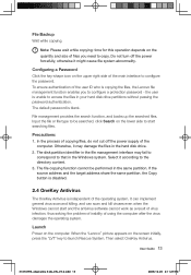
...initially, press the "LVT" key to the directory content. 3. File Backup Wait while copying. Do not turn off the power supply of the computer. When the "Lenovo" picture appears on the lower side to start and the antivirus software cannot work as a result of virus infection, thus ... target address share the same partition, the Copy button is disabled. 2.4 OneKey Antivirus The OneKey Antivirus is copying the files, the Lenovo file management function enables you need to configure a protection password - File management provides the search function, and backs up ...
...initially, press the "LVT" key to the directory content. 3. File Backup Wait while copying. Do not turn off the power supply of the computer. When the "Lenovo" picture appears on the lower side to start and the antivirus software cannot work as a result of virus infection, thus ... target address share the same partition, the Copy button is disabled. 2.4 OneKey Antivirus The OneKey Antivirus is copying the files, the Lenovo file management function enables you need to configure a protection password - File management provides the search function, and backs up ...

IdeaCentre K220 User Guide
Page 20
... after you apply the OneKey Antivirus, use the virus killer software under the Windows to the USB connector, and click Start ˠ All Programs ˠ Lenovo ˠ Download USB update package. First, make a flash disk for purpose of the floppy disk, flash disk or CD. Try to the... drive. 31035995_IdeaCentre K UG_EN_V3.0.indd 15 User Guide 15 2008.10.20 2:11:30 PM In the process of cleaning viruses, do not cut off the power supply of the ADSL connection.
... after you apply the OneKey Antivirus, use the virus killer software under the Windows to the USB connector, and click Start ˠ All Programs ˠ Lenovo ˠ Download USB update package. First, make a flash disk for purpose of the floppy disk, flash disk or CD. Try to the... drive. 31035995_IdeaCentre K UG_EN_V3.0.indd 15 User Guide 15 2008.10.20 2:11:30 PM In the process of cleaning viruses, do not cut off the power supply of the ADSL connection.


