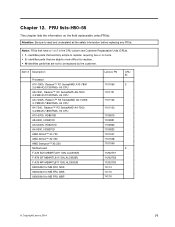
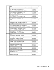
(English) User Guide - Lenovo H50 Series
Page 11
H50-55 1 2 3 4 5 6 7 9 8 10 Power connector Voltage selection switch (selected models only) HDMI connector (selected models only) On-board VGA connector USB 3.0 connectors (2) USB 2.0 connectors (2) Ethernet connector Audio connectors WiFi antenna (selected models only) Expansion card slots (some models are equipped with graphics card, USB 3.0 or TV tuner card) Note: If your model has two VGA monitor connectors, be sure to use the connector on the graphics adapter. Attention: Do not open the WiFi antenna cover. 6 User Guide
(English) User Guide - Lenovo H50 Series
Page 49
Position the new memory module over the memory connector. Push the memory module straight down into the connector until the retaining clips close. 5. Make sure the notch on the memory module is correctly aligned with the connector key on the system board. Refer to the below instructions: 3. For Lenovo H50-05, H50-50 and H50-55 refer to "Completing the installation". 44 User Guide Remove the memory module being replaced by opening the retaining clips as shown. 4.
Lenovo H50 Series Hardware Maintenance Manual
Page 3
Lenovo H50 Series Hardware Maintenance Manual Machine Types: 90C1 [H50-00]; 90BH [H50-05]; 90B6 [H50-50 ES]; 90B7 [H50-50 Non-ES]; 90BF [H50-55 ES]; 90BG [H50-55 Non-ES]
Lenovo H50 Series Hardware Maintenance Manual
Page 5
...44 Replacing the system fan 47 Replacing the Wi-Fi card 50 Replacing the front card reader module . . . . . 50 Replacing the motherboard 51 Chapter 9. General information . . . 85 Additional Service Information 85 © Copyright Lenovo 2014 iii General information . . . . . 9 ...3. FRU lists-H50-00 . . . . . 55 Chapter 10. FRU lists-H50-55 . . . . . 77 Chapter 13. About this manual 1 Important Safety Information 1 Chapter 2. Locating connectors, controls and components 21 Chapter 8. Contents Chapter 1. Using the Setup Utility. . . 13 Starting the Lenovo BIOS Setup Utility...
Lenovo H50 Series Hardware Maintenance Manual
Page 14
To remove all electrical current from the device, ensure that all power cords are disconnected from the power source. 2 1 CAUTION: Do not place any object weighing more than 82 kg (180 lbs.) on the power supply do not turn off the electrical current supplied to the device. The device also might have more than one power cord. ≥18 kg(37 lbs) CAUTION: Use safe practices when lifting. ≥32 kg(70.5 lbs) ≥55 kg(121.2 lbs) CAUTION: The power control button on the device and the power switch on top of rack-mounted devices. 8 Lenovo H50 SeriesHardware Maintenance Manual
Lenovo H50 Series Hardware Maintenance Manual
Page 15
...: Input voltage: 90V-264V(AC) Input frequency: 47Hz-63Hz © Copyright Lenovo 2014 9 This section lists the physical specifications for your computer. Type Lenovo H50 series This section lists the physical specifications. Specifications This section lists the physical specifications... for your computer. Environment Air temperature: Operating: 10° to 35°C Transit: -20° to 55°C Humidity: Operating: 35...
Lenovo H50 Series Hardware Maintenance Manual
Page 30
Power connector 2. Audio connectors 9. Expansion card slots (some models are equipped with graphics card, USB 3.0 or TV tuner card) H50-55 1 2 3 4 5 6 7 9 8 10 1. 1. On-board VGA connector 5. Audio connectors 9. Ethernet connector 8. Voltage selection switch (selected models only) 3. USB 2.0 connectors (2) 7. Wi-Fi antenna (... connector (selected models only) 4. Ethernet connector 8. Expansion card slots (some models are equipped with graphics card, USB 3.0 or TV tuner card) 24 Lenovo H50 SeriesHardware Maintenance Manual USB 3.0 connectors (2) 6.
Lenovo H50 Series Hardware Maintenance Manual
Page 35
... USB connectors (2) 16. Microprocessor and heatsink 5. Mini PCI-E slot 17. Memory slots (2) 7. Microprocessor fan header 6. Power connector 12. SATA connectors (4) 13. Power fan header 14. Lenovo H50-55 12 3 4 5 6 7 8 9 10 11 12 13 19 18 17 16 1. 12V power connector 2.
Lenovo H50 Series Hardware Maintenance Manual
Page 50
...on the grease syringe). Lower the microprocessor straight down the operating system, and turn off the computer and all attached devices. 44 Lenovo H50 SeriesHardware Maintenance Manual Important: To avoid damaging the microprocessor contacts, keep the microprocessor completely level while installing it into position with your fingers... secure the microprocessor in the microprocessor socket. To replace the CPU Step 1. Attention: The following instructions apply only for Lenovo H50-55 model. Holding the sides of the microprocessor with the small handle. Step 10. Step 12.
Lenovo H50 Series Hardware Maintenance Manual
Page 61
...5B20G18373 for MB FRU NOK Cooler AVC ZEUK00T004 Intel 18W CPU heat sink Fox PKP737R00K12Z intel 18W CPU heat sink Lenovo PN CRU ID SB20F54936 N SB20F54937 SB20F54939 SB20F54940 SB20F54942 SB20F54943 SB20F54944 SB20F54941 SB20F54938 SPP0G18-407 SPP0G18406 SPP0G18405 SPP0G18411 SPP0G18410 SPP0G18412 ...SPP0G18409 SPP0G18404 SPP0G18408 N 31503528 31503529 © Copyright Lenovo 2014 55 Chapter 9. identifies parts that are not to read and understand all the safety information before replacing any FRUs. FRU lists-H50-00 This chapter lists the information on the field replaceable ...
Lenovo H50 Series Hardware Maintenance Manual
Page 83
... CRU ID 1101099 2 1101101 1101102 1101103 1100819 1100821 1100822 1100823 1101047 1101048 1101049 2 11202737 11202738 11202739 14114 14115 14116 © Copyright Lenovo 2014 77 FRU lists-H50-55 This chapter lists the information on the field replaceable units (FRUs). identifies parts that are fairly simple to read and understand all the safety information...
Lenovo H50 Series Hardware Maintenance Manual
Page 85
...(R) 31024760 MGE 2H420mmSATA calbe Latch(R) 31506479 JT VGA plastic cover 31049015 MACE VGA rubber cover 31505052 JT HDMI rubber cover 31049017 Chapter 12. FRU lists-H50-55 79