User Guide
Page 3
...on select models 30 Chapter 3. OneKey Rescue system 33 OneKey Rescue system 33 Appendix A. Contents Chapter 1. CRU instructions 35 Replacing the battery 35 Replacing the hard disk drive 37 Replacing memory ...44 Replacing the wireless LAN card 48 Removing the optical drive 50 Trademarks 52...the Internet 31 Wired connection ...31 Wireless connection 32 Chapter 4. Learning the basics 16 First use...16 Using AC adapter and battery 18 Using the touchpad 20 Using the keyboard 21 Connecting external devices 24 Special keys and buttons 26 System status indicators 27 Securing...
...on select models 30 Chapter 3. OneKey Rescue system 33 OneKey Rescue system 33 Appendix A. Contents Chapter 1. CRU instructions 35 Replacing the battery 35 Replacing the hard disk drive 37 Replacing memory ...44 Replacing the wireless LAN card 48 Removing the optical drive 50 Trademarks 52...the Internet 31 Wired connection ...31 Wireless connection 32 Chapter 4. Learning the basics 16 First use...16 Using AC adapter and battery 18 Using the touchpad 20 Using the keyboard 21 Connecting external devices 24 Special keys and buttons 26 System status indicators 27 Securing...

User Guide
Page 12
e AC power adapter jack Connect the AC adapter here. The black ports are USB 3.0 ports. Note: For details, see "Connecting a universal serial bus (USB) device" on page 18. Note: • The blue ports are USB 2.0 ports. • For details, see "Using AC adapter and battery" on page 25. Chapter 1. Getting to know your computer d USB port (on select models) Connects to USB devices. f Combo audio jack 8
e AC power adapter jack Connect the AC adapter here. The black ports are USB 3.0 ports. Note: For details, see "Connecting a universal serial bus (USB) device" on page 18. Note: • The blue ports are USB 2.0 ports. • For details, see "Using AC adapter and battery" on page 25. Chapter 1. Getting to know your computer d USB port (on select models) Connects to USB devices. f Combo audio jack 8
User Guide
Page 19
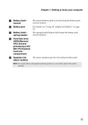
... to know your model, refer to keep the battery pack secured in place. The spring-loaded battery latch keeps the battery pack secured in place. Chapter 1. b Battery pack c Battery latch spring loaded For details, see "Using AC adapter and battery" on select models) The stereo speakers provide rich... and powerful sound. Note: For sound effects and speaker locations specific to your computer a Battery latch manual The manual battery latch is used to the actual product. 15 d Hard disk drive (HDD)/Memory/ CPU (Central processing unit)/ Mini ...
... to know your model, refer to keep the battery pack secured in place. The spring-loaded battery latch keeps the battery pack secured in place. Chapter 1. b Battery pack c Battery latch spring loaded For details, see "Using AC adapter and battery" on select models) The stereo speakers provide rich... and powerful sound. Note: For sound effects and speaker locations specific to your computer a Battery latch manual The manual battery latch is used to the actual product. 15 d Hard disk drive (HDD)/Memory/ CPU (Central processing unit)/ Mini ...
User Guide
Page 20
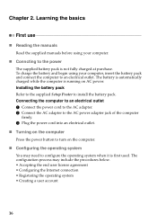
...to configure the operating system when it is first used. The configuration process may need to an electrical outlet. Chapter 2. The battery is automatically charged while the computer is not fully charged at purchase. Connecting the computer to an electrical outlet 1 Connect the ...the manuals Read the supplied manuals before using your computer. „ Conncting to install the battery pack. Installing the battery pack Refer to the supplied Setup Poster to the power The supplied battery pack is running on the computer. „ Configuring the operating system You may include ...
...to configure the operating system when it is first used. The configuration process may need to an electrical outlet. Chapter 2. The battery is automatically charged while the computer is not fully charged at purchase. Connecting the computer to an electrical outlet 1 Connect the ...the manuals Read the supplied manuals before using your computer. „ Conncting to install the battery pack. Installing the battery pack Refer to the supplied Setup Poster to the power The supplied battery pack is running on the computer. „ Configuring the operating system You may include ...

User Guide
Page 22
...are two main factors: • The amount of energy stored in the battery when you commence work. • The way you find that the battery power is not required. 18 Chapter 2. There are advised to insert the battery pack when using your computer to prevent small particles from fully charged. &#... the hard disk drive and how bright you make the computer display. „ Charging the battery When you use your computer. • To increase the life of battery power remaining by checking the battery icon in the notification area. Note: As each computer user has different habits and needs, ...
...are two main factors: • The amount of energy stored in the battery when you commence work. • The way you find that the battery power is not required. 18 Chapter 2. There are advised to insert the battery pack when using your computer to prevent small particles from fully charged. &#... the hard disk drive and how bright you make the computer display. „ Charging the battery When you use your computer. • To increase the life of battery power remaining by checking the battery icon in the notification area. Note: As each computer user has different habits and needs, ...
User Guide
Page 23
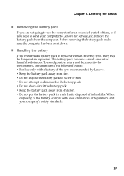
... from children. • Do not put the battery pack in trash that is replaced with a battery of the type recommended by Lenovo. • Keep the battery pack away from fire. • Do not expose the battery pack to water or rain. • Do not attempt to send your company's safety ...standards. 19 When disposing of the battery, comply with local ordinances or regulations and your computer to Lenovo for an extended period of in landfills. Before removing the battery pack, make sure the computer has been shut down. „ Handling the...
... from children. • Do not put the battery pack in trash that is replaced with a battery of the type recommended by Lenovo. • Keep the battery pack away from fire. • Do not expose the battery pack to water or rain. • Do not attempt to send your company's safety ...standards. 19 When disposing of the battery, comply with local ordinances or regulations and your computer to Lenovo for an extended period of in landfills. Before removing the battery pack, make sure the computer has been shut down. „ Handling the...

User Guide
Page 29
... the device with your computer. 25 Enabling Bluetooth communications on select models) If your computer has an integrated Bluetooth adapter card, it off to save battery power. • You need to pair the Bluetooth enabled device with your computer before you do not need to 10 meters range in open space...
... the device with your computer. 25 Enabling Bluetooth communications on select models) If your computer has an integrated Bluetooth adapter card, it off to save battery power. • You need to pair the Bluetooth enabled device with your computer before you do not need to 10 meters range in open space...

User Guide
Page 32
Chapter 2. Learning the basics a Caps lock indicator b Num lock indicator c Power status indicator d Battery status indicator e Wireless communication indicator f Hard disk drive indicator 28
Chapter 2. Learning the basics a Caps lock indicator b Num lock indicator c Power status indicator d Battery status indicator e Wireless communication indicator f Hard disk drive indicator 28

User Guide
Page 34
... the discrete GPU to set a password and enable it, a prompt appears on the screen each time you set the password, see the Help to preserve battery life; Once you power on the computer. Note: This password can be from being used unless you start high-definition movie playback or a 3D game... selected as the active GPU to the right of the screen in any combination. Chapter 2. Note: To enter BIOS setup utility, press F2 when the Lenovo logo appears on select models Optimus is performed automatically without user intervention. 30
... the discrete GPU to set a password and enable it, a prompt appears on the screen each time you set the password, see the Help to preserve battery life; Once you power on the computer. Note: This password can be from being used unless you start high-definition movie playback or a 3D game... selected as the active GPU to the right of the screen in any combination. Chapter 2. Note: To enter BIOS setup utility, press F2 when the Lenovo logo appears on select models Optimus is performed automatically without user intervention. 30

User Guide
Page 37
...Rescue system without an integrated optical drive support the creation of recovery discs may take some time, connect the AC adapter and battery pack to launch Lenovo OneKey Recovery. however an appropriate external optical drive is needed to back up the system partition on the desktop to your ...space depends on the file size of the mirror image file (based on the size of operating system and preinstalled software). „ Using Lenovo OneKey Recovery (within Windows operating system) In Windows operating system, double click the OneKey Recovery system Icon on the hard disk drive, ...
...Rescue system without an integrated optical drive support the creation of recovery discs may take some time, connect the AC adapter and battery pack to launch Lenovo OneKey Recovery. however an appropriate external optical drive is needed to back up the system partition on the desktop to your ...space depends on the file size of the mirror image file (based on the size of operating system and preinstalled software). „ Using Lenovo OneKey Recovery (within Windows operating system) In Windows operating system, double click the OneKey Recovery system Icon on the hard disk drive, ...
User Guide
Page 39
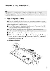
... the computer. 2 Close the computer display, and turn off the computer, or enter hibernation mode. Note: If you are the same for the Lenovo G480/G485/G580/G585/G780. Appendix A. G480/G485/G580/G585 1 3 2 35 Any other battery could ignite or explode. CRU instructions Note: • The illustrations used in the direction shown by...
... the computer. 2 Close the computer display, and turn off the computer, or enter hibernation mode. Note: If you are the same for the Lenovo G480/G485/G580/G585/G780. Appendix A. G480/G485/G580/G585 1 3 2 35 Any other battery could ignite or explode. CRU instructions Note: • The illustrations used in the direction shown by...

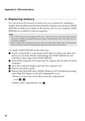
User Guide
Page 40
Connect the AC adapter and the cables to the locked position. 6 Turn the computer over again. Appendix A. CRU instructions G780 1 3 2 4 Install a fully charged battery. 5 Slide the manual battery latch to the computer again. 36
Connect the AC adapter and the cables to the locked position. 6 Turn the computer over again. Appendix A. CRU instructions G780 1 3 2 4 Install a fully charged battery. 5 Slide the manual battery latch to the computer again. 36
User Guide
Page 42
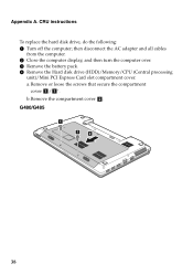
then disconnect the AC adapter and all cables from the computer. 2 Close the computer display, and then turn the computer over. 3 Remove the battery pack. 4 Remove the Hard disk drive (HDD)/Memory/CPU (Central processing unit)/Mini PCI Express Card slot compartment cover. b.Remove the compartment cover b. G480/G485 1 1 2 38 a.Remove or loose the screws that secure the compartment cover a/ a '. CRU instructions To replace the hard disk drive, do the following: 1 Turn off the computer; Appendix A.
then disconnect the AC adapter and all cables from the computer. 2 Close the computer display, and then turn the computer over. 3 Remove the battery pack. 4 Remove the Hard disk drive (HDD)/Memory/CPU (Central processing unit)/Mini PCI Express Card slot compartment cover. b.Remove the compartment cover b. G480/G485 1 1 2 38 a.Remove or loose the screws that secure the compartment cover a/ a '. CRU instructions To replace the hard disk drive, do the following: 1 Turn off the computer; Appendix A.

User Guide
Page 47
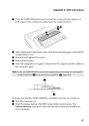
D Reinstall the battery pack. C Reinstall and tighten the screws. B After aligning the attachment clips with their matching gaps, reinstall the compartment cover. CRU instructions A Reinstall the frame fixing screws. E Turn the computer over again. Connect the AC adapter and the cables to the computer again. 43 Appendix A.
D Reinstall the battery pack. C Reinstall and tighten the screws. B After aligning the attachment clips with their matching gaps, reinstall the compartment cover. CRU instructions A Reinstall the frame fixing screws. E Turn the computer over again. Connect the AC adapter and the cables to the computer again. 43 Appendix A.
User Guide
Page 48
... option-in various capacities. Disconnect the AC adapter and all cables from the computer. 3 Close the computer display, and turn the computer over. 4 Remove the battery again. 5 Remove the Hard disk drive (HDD)/Memory/CPU (Central processing unit)/Mini PCI Express Card slot compartment cover. Refer to reduce any static elec...
... option-in various capacities. Disconnect the AC adapter and all cables from the computer. 3 Close the computer display, and turn the computer over. 4 Remove the battery again. 5 Remove the Hard disk drive (HDD)/Memory/CPU (Central processing unit)/Mini PCI Express Card slot compartment cover. Refer to reduce any static elec...
User Guide
Page 51
... the latches on both edges of memory installed in SLOT-1 ( : upper slot). Connect the AC adapter and the cables to the computer again. A Reinstall the battery. The BIOS setup utility screen opens. B Turn the computer over again. Appendix A. b a To make sure that the DDR3 SDRAM is used on . 2 Hold F2 during...
... the latches on both edges of memory installed in SLOT-1 ( : upper slot). Connect the AC adapter and the cables to the computer again. A Reinstall the battery. The BIOS setup utility screen opens. B Turn the computer over again. Appendix A. b a To make sure that the DDR3 SDRAM is used on . 2 Hold F2 during...
User Guide
Page 52
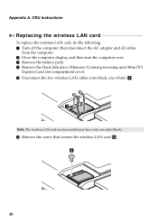
then disconnect the AC adapter and all cables from the computer. 2 Close the computer display, and then turn the computer over. 3 Remove the battery pack. 4 Remove the Hard disk drive/Memory/Central processing unit/Mini PCI Express Card slot compartment cover. 5 Disconnect the two wireless LAN cables (one black, ...
then disconnect the AC adapter and all cables from the computer. 2 Close the computer display, and then turn the computer over. 3 Remove the battery pack. 4 Remove the Hard disk drive/Memory/Central processing unit/Mini PCI Express Card slot compartment cover. 5 Disconnect the two wireless LAN cables (one black, ...

User Guide
Page 53
... AC adapter and the cables to the computer again. 49 C Turn the computer over again. A Reinstall the compartment cover and tighten the screws. B Reinstall the battery pack. Note: When installing or reinstalling the wireless card: • In models with a wireless LAN card that has two cables: Plug the black cable (MAIN...
... AC adapter and the cables to the computer again. 49 C Turn the computer over again. A Reinstall the compartment cover and tighten the screws. B Reinstall the battery pack. Note: When installing or reinstalling the wireless card: • In models with a wireless LAN card that has two cables: Plug the black cable (MAIN...
User Guide
Page 55
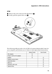
AC adapter Power cord for your computer, and informs you of where to find replacement instructions. CRU instructions G780 1 Remove the screw shown in the illustration a . 2 Gently pull the optical drive out b . 1 2 The following table provides a list of CRUs (Customer Replaceable Units) for AC adapter Battery Bottom access doors Hard disk drive Memory Wireless LAN card Optical drive Setup Poster O O O User Guide O O O O O O 51 Appendix A.
AC adapter Power cord for your computer, and informs you of where to find replacement instructions. CRU instructions G780 1 Remove the screw shown in the illustration a . 2 Gently pull the optical drive out b . 1 2 The following table provides a list of CRUs (Customer Replaceable Units) for AC adapter Battery Bottom access doors Hard disk drive Memory Wireless LAN card Optical drive Setup Poster O O O User Guide O O O O O O 51 Appendix A.

User Guide
Page 57
Index A AC adapter Using 18 B Battery Charging 18 Bluetooth Connecting 25 C Camera 4, 23 F Function key combinations ...........22 K Keyboard Using 21 M Meomory card reader 24 Microphone Built-in 4 O OneKey Rescue System button...33 P Password Using 30 S Security 29 T Touchpad 20 U USB port 6, 8, 25 V VeriFace Using 29 53
Index A AC adapter Using 18 B Battery Charging 18 Bluetooth Connecting 25 C Camera 4, 23 F Function key combinations ...........22 K Keyboard Using 21 M Meomory card reader 24 Microphone Built-in 4 O OneKey Rescue System button...33 P Password Using 30 S Security 29 T Touchpad 20 U USB port 6, 8, 25 V VeriFace Using 29 53


