
Erazer X5 Series User Guide
Page 40
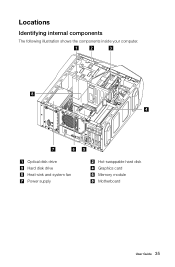
Locations Identifying internal components The following illustration shows the components inside your computer. 1 2 3 8 4 7 65 Optical disk drive Hard disk drive Heat-sink and system fan Power supply Hot-swappable hard disk Graphics card Memory module Motherboard User Guide 35
Locations Identifying internal components The following illustration shows the components inside your computer. 1 2 3 8 4 7 65 Optical disk drive Hard disk drive Heat-sink and system fan Power supply Hot-swappable hard disk Graphics card Memory module Motherboard User Guide 35

Erazer X5 Series User Guide
Page 41
The following illustration shows the locations of devices that are factory-installed or that you can install later. It provides basic computer functions and supports a variety of the different parts on the system board The system board (also known as the "mainboard" or "motherboard") is the main circuit board in your computer. Identifying parts on the system board. 1 2 3 4 56 7 8 9 10 21 20 11 12 19 18 17 16 12V power connector Microprocessor and heat sink Microprocessor fan header Memory slots (4) Overclocking LED header2 Overclocking LED header1 36 User Guide 15 14 13
The following illustration shows the locations of devices that are factory-installed or that you can install later. It provides basic computer functions and supports a variety of the different parts on the system board The system board (also known as the "mainboard" or "motherboard") is the main circuit board in your computer. Identifying parts on the system board. 1 2 3 4 56 7 8 9 10 21 20 11 12 19 18 17 16 12V power connector Microprocessor and heat sink Microprocessor fan header Memory slots (4) Overclocking LED header2 Overclocking LED header1 36 User Guide 15 14 13
Erazer X5 Series User Guide
Page 40
Locations Identifying internal components The following illustration shows the components inside your computer. 1 2 3 8 4 7 65 Optical disk drive Hard disk drive Heat-sink and system fan Power supply Hot-swappable hard disk Graphics card Memory module Motherboard User Guide 35
Locations Identifying internal components The following illustration shows the components inside your computer. 1 2 3 8 4 7 65 Optical disk drive Hard disk drive Heat-sink and system fan Power supply Hot-swappable hard disk Graphics card Memory module Motherboard User Guide 35

Erazer X5 Series User Guide
Page 41
Identifying parts on the system board. 1 2 3 4 56 7 8 9 10 21 20 11 12 19 18 17 16 12V power connector Microprocessor and heat sink Microprocessor fan header Memory slots (4) Overclocking LED header2 Overclocking LED header1 36 User Guide 15 14 13 It provides basic computer functions and supports a variety of the different parts on the system board The system board (also known as the "mainboard" or "motherboard") is the main circuit board in your computer. The following illustration shows the locations of devices that are factory-installed or that you can install later.
Identifying parts on the system board. 1 2 3 4 56 7 8 9 10 21 20 11 12 19 18 17 16 12V power connector Microprocessor and heat sink Microprocessor fan header Memory slots (4) Overclocking LED header2 Overclocking LED header1 36 User Guide 15 14 13 It provides basic computer functions and supports a variety of the different parts on the system board The system board (also known as the "mainboard" or "motherboard") is the main circuit board in your computer. The following illustration shows the locations of devices that are factory-installed or that you can install later.
Lenovo Erazer X510 Hardware Maintenance Manual
Page 5
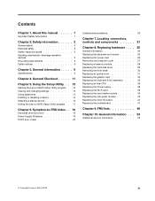
... Enabling or disabling a device 15 Selecting a startup device 16 Exiting the Lenovo BIOS Setup Utility program . . 17 Chapter 6. General information . . . 53 Additional Service Information 53 © Copyright Lenovo 2013, 2013 iii Locating connectors, controls and components 21 Chapter 8. About...the Wi-Fi card 39 Replacing the card reader module 40 Replacing the usb-audio module 42 Replacing the front I/O board 44 Replacing the motherboard 47 Chapter 9. FRU lists 49 Chapter 10. General information . . . . . 9 Specifications 9 Chapter 4. Safety information 3 General ...
... Enabling or disabling a device 15 Selecting a startup device 16 Exiting the Lenovo BIOS Setup Utility program . . 17 Chapter 6. General information . . . 53 Additional Service Information 53 © Copyright Lenovo 2013, 2013 iii Locating connectors, controls and components 21 Chapter 8. About...the Wi-Fi card 39 Replacing the card reader module 40 Replacing the usb-audio module 42 Replacing the front I/O board 44 Replacing the motherboard 47 Chapter 9. FRU lists 49 Chapter 10. General information . . . . . 9 Specifications 9 Chapter 4. Safety information 3 General ...
Lenovo Erazer X510 Hardware Maintenance Manual
Page 29
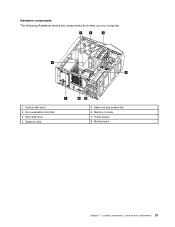
Graphics card 65 5. Memory module 7. Power supply 8. Hot-swappable hard disk 3. Hard disk drive 4. Locating connectors, controls and components 23 Optical disk drive 2. Motherboard Chapter 7. Hardware components The following illustration shows the components that make up your computer. 1 2 3 8 4 7 1. Heat-sink and system fan 6.
Graphics card 65 5. Memory module 7. Power supply 8. Hot-swappable hard disk 3. Hard disk drive 4. Locating connectors, controls and components 23 Optical disk drive 2. Motherboard Chapter 7. Hardware components The following illustration shows the components that make up your computer. 1 2 3 8 4 7 1. Heat-sink and system fan 6.

Lenovo Erazer X510 Hardware Maintenance Manual
Page 30
... connectors (2) 17. PCI express X 1 adapter slots (2) 20. System fan header 24 Lenovo Erazer X510Hardware Maintenance Manual The following illustration shows the location of connectors and components on the motherboard The motherboard (sometimes called the planar or system board) is the main circuit board in your computer....fan header 14. Mini PCI-E slot 18. Overclocking LED header2 6. Power connector 10. Identifying parts on the front of the motherboard. 1 2 3 4 56 7 8 9 10 21 20 11 12 19 18 17 1. 12V power connector 2. Serial (COM2) connector 16. Front USB...
... connectors (2) 17. PCI express X 1 adapter slots (2) 20. System fan header 24 Lenovo Erazer X510Hardware Maintenance Manual The following illustration shows the location of connectors and components on the motherboard The motherboard (sometimes called the planar or system board) is the main circuit board in your computer....fan header 14. Mini PCI-E slot 18. Overclocking LED header2 6. Power connector 10. Identifying parts on the front of the motherboard. 1 2 3 4 56 7 8 9 10 21 20 11 12 19 18 17 1. 12V power connector 2. Serial (COM2) connector 16. Front USB...

Lenovo Erazer X510 Hardware Maintenance Manual
Page 33
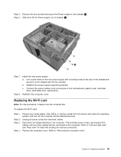
...Attention: Turn off the computer and all power cords from the connector on a soft flat surface for help with locating the various connectors. Lenovo recommends that you use a blanket, towel, or other soft cloth to protect the computer screen from scratches or other cables that are ...connected to place the computer face-down the operating system, and turn off the computer and wait 3 to 5 minutes to the connectors on the motherboard. Remove any other damage. Chapter 8. Replacing hardware 27 Install the new adapter: a. Note: It may be helpful to the computer. Step ...
...Attention: Turn off the computer and all power cords from the connector on a soft flat surface for help with locating the various connectors. Lenovo recommends that you use a blanket, towel, or other soft cloth to protect the computer screen from scratches or other cables that are ...connected to place the computer face-down the operating system, and turn off the computer and wait 3 to 5 minutes to the connectors on the motherboard. Remove any other damage. Chapter 8. Replacing hardware 27 Install the new adapter: a. Note: It may be helpful to the computer. Step ...

Lenovo Erazer X510 Hardware Maintenance Manual
Page 41
...the microprocessor. Remove the computer cover. Remove the four screws that are connected to the computer. Reconnect the microprocessor fan power cable to the motherboard and chassis. 1 Remove the heat-sink assembly as shown. 2 Step 8. Step 3. Step 6. Disconnect the microprocessor fan cable from the ... cover. Refer to place five drops of grease on the top of grease should be 0.03ml (3 tick marks on the motherboard. Line up the screws on the motherboard, then secure it helps to "Removing the computer cover". Step 2. To replace the heat-sink and fan assembly: Step ...
...the microprocessor. Remove the computer cover. Remove the four screws that are connected to the computer. Reconnect the microprocessor fan power cable to the motherboard and chassis. 1 Remove the heat-sink assembly as shown. 2 Step 8. Step 3. Step 6. Disconnect the microprocessor fan cable from the ... cover. Refer to place five drops of grease on the top of grease should be 0.03ml (3 tick marks on the motherboard. Line up the screws on the motherboard, then secure it helps to "Removing the computer cover". Step 2. To replace the heat-sink and fan assembly: Step ...

Lenovo Erazer X510 Hardware Maintenance Manual
Page 43
... the gold contacts on the grease syringe). Holding the sides of the microprocessor with your fingers, remove the protective cover 1 that the notches on the motherboard. Each drop of the microprocessor.
... the gold contacts on the grease syringe). Holding the sides of the microprocessor with your fingers, remove the protective cover 1 that the notches on the motherboard. Each drop of the microprocessor.
Lenovo Erazer X510 Hardware Maintenance Manual
Page 45
Line up the holes on the new power supply with mounting holes on the motherboard, graphic card, hard disk drive, solid state drive, optical drive. b. Unplug all attached devices. Refer to the connectors on the rear of chassis. 2 Step 7. Replacing ...
Line up the holes on the new power supply with mounting holes on the motherboard, graphic card, hard disk drive, solid state drive, optical drive. b. Unplug all attached devices. Refer to the connectors on the rear of chassis. 2 Step 7. Replacing ...

Lenovo Erazer X510 Hardware Maintenance Manual
Page 53
... card. Step 9. Refer to "Replacing the heat-sink and fan assembly". Step 8. Refer to the chassis. Install the new motherboard: a. To replace the motherboard: Step 1. Step 4. Remove the heat-sink and fan assembly. Disconnect the all attached devices. Remove the eight screws that are... to "Replacing the CPU". Step 6. Slide then lift up the holes on the new motherboard with screws. Step 5. Line up the motherboard to "Removing the computer cover". Replacing the motherboard Note: For this procedure, it . Unplug all power cords from the drives, shut down...
... card. Step 9. Refer to "Replacing the heat-sink and fan assembly". Step 8. Refer to the chassis. Install the new motherboard: a. To replace the motherboard: Step 1. Step 4. Remove the heat-sink and fan assembly. Disconnect the all attached devices. Remove the eight screws that are... to "Replacing the CPU". Step 6. Slide then lift up the holes on the new motherboard with screws. Step 5. Line up the motherboard to "Removing the computer cover". Replacing the motherboard Note: For this procedure, it . Unplug all power cords from the drives, shut down...
Lenovo Erazer X510 Hardware Maintenance Manual
Page 54
c. d. Connect the all cables to the new motherboard. Reattach the graphic card. Step 14. Reattach the Wi-Fi card, CPU, heat-sink assembly, graphic card, memory module to the new motherboard. Reattach the computer cover. 48 Lenovo Erazer X510Hardware Maintenance Manual b.
c. d. Connect the all cables to the new motherboard. Reattach the graphic card. Step 14. Reattach the Wi-Fi card, CPU, heat-sink assembly, graphic card, memory module to the new motherboard. Reattach the computer cover. 48 Lenovo Erazer X510Hardware Maintenance Manual b.

Lenovo Erazer X510 Hardware Maintenance Manual
Page 55
...Be sure to replace, requiring few or no tools. • 2- Item# 1 2 3 4 5 6 Description Motherboard MB FRU NOK MB FRU W8S MB FRU W8P CPU I I74770K 3.5/1600/8/1150 84 CPU I I54670K 3.4/1600/6/1150 84... 1100782 N 1100784 N 36200512 N 36200513 N 1100649 2 1100213 2 1100651 2 1100652 2 1100681 2 1100217 2 1100647 2 1100669 2 1100648 2 11201703 2 11201867 2 11201704 2 11201702 2 11202298 2 © Copyright Lenovo 2013, 2013 49 FRU lists This chapter lists the information on the field replaceable units (FRUs). identifies parts that are fairly simple to read and...
...Be sure to replace, requiring few or no tools. • 2- Item# 1 2 3 4 5 6 Description Motherboard MB FRU NOK MB FRU W8S MB FRU W8P CPU I I74770K 3.5/1600/8/1150 84 CPU I I54670K 3.4/1600/6/1150 84... 1100782 N 1100784 N 36200512 N 36200513 N 1100649 2 1100213 2 1100651 2 1100652 2 1100681 2 1100217 2 1100647 2 1100669 2 1100648 2 11201703 2 11201867 2 11201704 2 11201702 2 11202298 2 © Copyright Lenovo 2013, 2013 49 FRU lists This chapter lists the information on the field replaceable units (FRUs). identifies parts that are fairly simple to read and...


