(English) System Update 5.0 Deployment Guide
Page 47
.... This categorization also defines the severity level of each category, see the following registry value to YES: HKEY_LOCAL_MACHINE\SOFTWARE\Lenovo\System Update \Preferences\UserSettings\General\IgnoreLocalLicense Note: Using silent command scripts to recognize license agreements works only if you choose...Recovery® program. For a description of the package. Any BIOS or driver upgrade that may impact a small group of its battery life. • Optional packages will display search results in data loss, system malfunction, or hardware failure. A software patch to ...
.... This categorization also defines the severity level of each category, see the following registry value to YES: HKEY_LOCAL_MACHINE\SOFTWARE\Lenovo\System Update \Preferences\UserSettings\General\IgnoreLocalLicense Note: Using silent command scripts to recognize license agreements works only if you choose...Recovery® program. For a description of the package. Any BIOS or driver upgrade that may impact a small group of its battery life. • Optional packages will display search results in data loss, system malfunction, or hardware failure. A software patch to ...
Hardware Maintenance Manual - Lenovo E49
Page 3
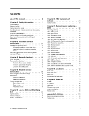
...emissions notices 92 Trademarks 92 © Copyright Lenovo 2012, 2013 i Lenovo E49 and ZhaoYang E49 37 Specifications 37 Status indicators 38 Fn key combinations 39 Chapter 6. Removing and replacing a FRU 43 General guidelines 43 1010 Battery pack 44 1020 Optical drive 44 1030 Bottom... devices that are sensitive to do first 29 Power system checkout 30 Checking the ac power adapter 30 Checking operational charging 31 Checking the battery pack 31 Chapter 4. Contents About this manual iii Chapter 1. General checkout . . . . . 29 What to electrostatic discharge 3 ...
...emissions notices 92 Trademarks 92 © Copyright Lenovo 2012, 2013 i Lenovo E49 and ZhaoYang E49 37 Specifications 37 Status indicators 38 Fn key combinations 39 Chapter 6. Removing and replacing a FRU 43 General guidelines 43 1010 Battery pack 44 1020 Optical drive 44 1030 Bottom... devices that are sensitive to do first 29 Power system checkout 30 Checking the ac power adapter 30 Checking operational charging 31 Checking the battery pack 31 Chapter 4. Contents About this manual iii Chapter 1. General checkout . . . . . 29 What to electrostatic discharge 3 ...

Hardware Maintenance Manual - Lenovo E49
Page 9
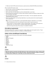
... Disconnect the power cord. 3. A third-wire ground connector in identifying potentially unsafe conditions. If any unsafe conditions are any non-Lenovo alterations. 7. Checklist: 1. Insulation must determine how serious the apparent hazard could be the type specified in charge between the external... ground pin and the frame ground. Use caution; Check for cracked or bulging batteries. 5. Safety inspection guide The purpose of any potentially unsafe conditions, use good judgment to identify potential safety hazards ...
... Disconnect the power cord. 3. A third-wire ground connector in identifying potentially unsafe conditions. If any unsafe conditions are any non-Lenovo alterations. 7. Checklist: 1. Insulation must determine how serious the apparent hazard could be the type specified in charge between the external... ground pin and the frame ground. Use caution; Check for cracked or bulging batteries. 5. Safety inspection guide The purpose of any potentially unsafe conditions, use good judgment to identify potential safety hazards ...
Hardware Maintenance Manual - Lenovo E49
Page 10
.... Make sure that meets the specific service requirement. Proper grounding of the electrical outlet can use coax or connector-outside shells on a double-insulated or battery-operated system, use of the computer is insulative and retains a charge even when you use have been certified (ISO 9000) as fully effective. When working...
.... Make sure that meets the specific service requirement. Proper grounding of the electrical outlet can use coax or connector-outside shells on a double-insulated or battery-operated system, use of the computer is insulative and retains a charge even when you use have been certified (ISO 9000) as fully effective. When working...
Hardware Maintenance Manual - Lenovo E49
Page 33
... of damaging the computer. • Before installing the latest utility, make sure that board, and then replace the other one. © Copyright Lenovo 2012, 2013 27 Chapter 2. Go to improve the computer performance, you have both a processor board and a system board. An untrained person runs... the risk of them does not correct the problem, reinstall that the battery is fully charged and an ac power adapter is replaced, ensure that all machine types supported by product category 3. To download software fixes,...
... of damaging the computer. • Before installing the latest utility, make sure that board, and then replace the other one. © Copyright Lenovo 2012, 2013 27 Chapter 2. Go to improve the computer performance, you have both a processor board and a system board. An untrained person runs... the risk of them does not correct the problem, reinstall that the battery is fully charged and an ac power adapter is replaced, ensure that all machine types supported by product category 3. To download software fixes,...
Hardware Maintenance Manual - Lenovo E49
Page 36
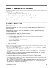
... computer password (making the computer unusable) • Sticky keys caused by spilling a liquid onto the keyboard • Use of an incorrect ac power adapter on laptop products The following : 1. Power system checkout To verify a symptom, do the following figure: Pin Voltage (V dc) 1 +20 2 0 2 1 Note: Output ...on page 30 • "Checking operational charging" on page 31 • "Checking the battery pack" on page 31 Checking the ac power adapter You are servicing. 3. Check that the battery pack supplies power when you are here because the computer fails only when the ac power ...
... computer password (making the computer unusable) • Sticky keys caused by spilling a liquid onto the keyboard • Use of an incorrect ac power adapter on laptop products The following : 1. Power system checkout To verify a symptom, do the following figure: Pin Voltage (V dc) 1 +20 2 0 2 1 Note: Output ...on page 30 • "Checking operational charging" on page 31 • "Checking the battery pack" on page 31 Checking the ac power adapter You are servicing. 3. Check that the battery pack supplies power when you are here because the computer fails only when the ac power ...
Hardware Maintenance Manual - Lenovo E49
Page 37
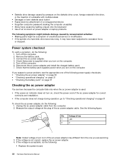
... not charged, go to Chapter 5 "Lenovo E49 and ZhaoYang E49" on , replace the system board. Note: Noise from the ac power adapter does not always indicate a defect. Press the recovery button to 30 K Ω. To check the battery pack, do the following : 1. Remove the battery pack and measure the voltage between battery terminals 5 and 7. Perform operational...
... not charged, go to Chapter 5 "Lenovo E49 and ZhaoYang E49" on , replace the system board. Note: Noise from the ac power adapter does not always indicate a defect. Press the recovery button to 30 K Ω. To check the battery pack, do the following : 1. Remove the battery pack and measure the voltage between battery terminals 5 and 7. Perform operational...
Hardware Maintenance Manual - Lenovo E49
Page 40
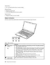
... any operation with the keyboard, the hard disk drive, the parallel connector, or the diskette drive within that time. • If the battery indicator blinks orange, indicating that the battery power is low. The computer does not start until the password is no service procedure to the BIOS and change the system...
... any operation with the keyboard, the hard disk drive, the parallel connector, or the diskette drive within that time. • If the battery indicator blinks orange, indicating that the battery power is low. The computer does not start until the password is no service procedure to the BIOS and change the system...
Hardware Maintenance Manual - Lenovo E49
Page 44
...drive is continuing. When the battery charge level reaches 20%, the blinking color changes to blue. • Amber: The battery discharge level is between 5% and 20%, and charging is powered off. When the battery charge level reaches 80%, the battery status indicator stops blinking, but... the charging might continue until the battery is 100% charged. • Slow blinking amber: The battery charge level is between 5% and 20%. • Fast blinking amber: The battery charge or discharge level...
...drive is continuing. When the battery charge level reaches 20%, the blinking color changes to blue. • Amber: The battery discharge level is between 5% and 20%, and charging is powered off. When the battery charge level reaches 80%, the battery status indicator stops blinking, but... the charging might continue until the battery is 100% charged. • Slow blinking amber: The battery charge level is between 5% and 20%. • Fast blinking amber: The battery charge or discharge level...
Hardware Maintenance Manual - Lenovo E49
Page 49
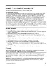
...the CRU yourself or you have made sure that have been trained and certified. Follow the on page 41. 3. See your Lenovo Limited Warranty documentation for your product. Before replacing any notes that a Service Provider install the CRU according to replacement. Remove them ...be found at http://www.lenovo.com/UserManuals. CRU information and replacement instructions are shipped with the replacement CRU; An electronic version of each FRU replacement procedure. When return is your product and are available from electrical outlets, remove the battery pack, and then disconnect...
...the CRU yourself or you have made sure that have been trained and certified. Follow the on page 41. 3. See your Lenovo Limited Warranty documentation for your product. Before replacing any notes that a Service Provider install the CRU according to replacement. Remove them ...be found at http://www.lenovo.com/UserManuals. CRU information and replacement instructions are shipped with the replacement CRU; An electronic version of each FRU replacement procedure. When return is your product and are available from electrical outlets, remove the battery pack, and then disconnect...
Hardware Maintenance Manual - Lenovo E49
Page 50
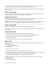
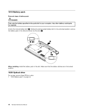
Holding the spring-loaded battery latch in the unlocked position, remove the battery pack in the direction shown by the arrow 2 . 1 2 2 When installing: Install the battery pack in the parts list for your computer. Unlock the manual battery latch 1 . 1010 Battery pack Removal steps of battery pack DANGER Use only the battery specified in the slot. Make sure that the battery latches are in the locked position. 1020 Optical drive For access, remove these FRUs in order: • "1010 Battery pack" on page 44 44 Hardware Maintenance Manual Any other battery could ignite or explode.
Holding the spring-loaded battery latch in the unlocked position, remove the battery pack in the direction shown by the arrow 2 . 1 2 2 When installing: Install the battery pack in the parts list for your computer. Unlock the manual battery latch 1 . 1010 Battery pack Removal steps of battery pack DANGER Use only the battery specified in the slot. Make sure that the battery latches are in the locked position. 1020 Optical drive For access, remove these FRUs in order: • "1010 Battery pack" on page 44 44 Hardware Maintenance Manual Any other battery could ignite or explode.
Hardware Maintenance Manual - Lenovo E49
Page 52
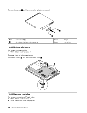
Step 1 Screw (quantity) M2 × 3 mm, flat-head, nylon-coated (2) 1030 Bottom slot cover For access, remove this FRU: • "1010 Battery pack" on page 44 Removal steps of bottom slot cover Loosen the screws 1 , and then remove the cover 2 . 2 1 2 1 Color Black Torque 1.85 kgf-cm 1 1040 Memory modules For access, remove these FRUs in order: • "1010 Battery pack" on page 44 • "1030 Bottom slot cover" on page 46 46 Hardware Maintenance Manual Remove the screws 1 and then remove the optical drive bracket.
Step 1 Screw (quantity) M2 × 3 mm, flat-head, nylon-coated (2) 1030 Bottom slot cover For access, remove this FRU: • "1010 Battery pack" on page 44 Removal steps of bottom slot cover Loosen the screws 1 , and then remove the cover 2 . 2 1 2 1 Color Black Torque 1.85 kgf-cm 1 1040 Memory modules For access, remove these FRUs in order: • "1010 Battery pack" on page 44 • "1030 Bottom slot cover" on page 46 46 Hardware Maintenance Manual Remove the screws 1 and then remove the optical drive bracket.
Hardware Maintenance Manual - Lenovo E49
Page 53
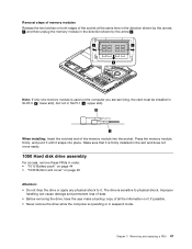
... is firmly installed in the slot and does not move easily. 1050 Hard disk drive assembly For access, remove these FRUs in order: • "1010 Battery pack" on page 44 • "1030 Bottom slot cover" on page 46 Attention: • Do not drop the drive or apply any physical shock to...
... is firmly installed in the slot and does not move easily. 1050 Hard disk drive assembly For access, remove these FRUs in order: • "1010 Battery pack" on page 44 • "1030 Bottom slot cover" on page 46 Attention: • Do not drop the drive or apply any physical shock to...
Hardware Maintenance Manual - Lenovo E49
Page 55
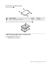
Removing and replacing a FRU 49 Removal steps of hard disk drive bracket Remove the screws 1 . 1 1 1 1 Step 1 Screw (quantity) M3 × 3 mm, flat-head, nylon-coated (4) Color Black Remove the hard disk drive bracket in the direction shown by the arrow 2 . 2 Torque 4.0 kgf-cm 1060 PCI Express Mini Card for wireless LAN For access, remove these FRUs in order: • "1010 Battery pack" on page 44 • "1030 Bottom slot cover" on page 46 Chapter 7.
Removing and replacing a FRU 49 Removal steps of hard disk drive bracket Remove the screws 1 . 1 1 1 1 Step 1 Screw (quantity) M3 × 3 mm, flat-head, nylon-coated (4) Color Black Remove the hard disk drive bracket in the direction shown by the arrow 2 . 2 Torque 4.0 kgf-cm 1060 PCI Express Mini Card for wireless LAN For access, remove these FRUs in order: • "1010 Battery pack" on page 44 • "1030 Bottom slot cover" on page 46 Chapter 7.
Hardware Maintenance Manual - Lenovo E49
Page 57
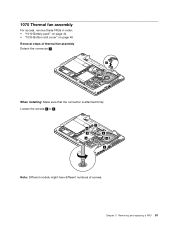
Removing and replacing a FRU 51 Chapter 7. Loosen the screws 2 to 8 . 7 8 2 6 5 4 3 Note: Different models might have different numbers of thermal fan assembly Detach the connector 1 . 1 When installing: Make sure that the connector is attached firmly. 1070 Thermal fan assembly For access, remove these FRUs in order: • "1010 Battery pack" on page 44 • "1030 Bottom slot cover" on page 46 Removal steps of screws.
Removing and replacing a FRU 51 Chapter 7. Loosen the screws 2 to 8 . 7 8 2 6 5 4 3 Note: Different models might have different numbers of thermal fan assembly Detach the connector 1 . 1 When installing: Make sure that the connector is attached firmly. 1070 Thermal fan assembly For access, remove these FRUs in order: • "1010 Battery pack" on page 44 • "1030 Bottom slot cover" on page 46 Removal steps of screws.
Hardware Maintenance Manual - Lenovo E49
Page 59
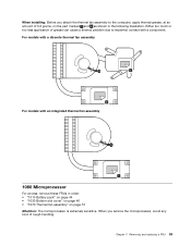
... attach the thermal fan assembly to imperfect contact with an integrated thermal fan assembly a 1080 Microprocessor For access, remove these FRUs in order: • "1010 Battery pack" on page 44 • "1030 Bottom slot cover" on page 46 • "1070 Thermal fan assembly" on the part marked a and b as shown in...
... attach the thermal fan assembly to imperfect contact with an integrated thermal fan assembly a 1080 Microprocessor For access, remove these FRUs in order: • "1010 Battery pack" on page 44 • "1030 Bottom slot cover" on page 46 • "1070 Thermal fan assembly" on the part marked a and b as shown in...
Hardware Maintenance Manual - Lenovo E49
Page 60
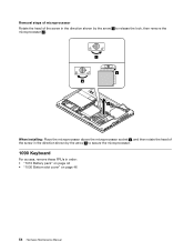
Removal steps of microprocessor Rotate the head of the screw in the direction shown by the arrow 1 to release the lock, then remove the microprocessor 2 . 1 a b 2 When installing: Place the microprocessor above the microprocessor socket a , and then rotate the head of the screw in the direction shown by the arrow b to secure the microprocessor. 1090 Keyboard For access, remove these FRUs in order: • "1010 Battery pack" on page 44 • "1030 Bottom slot cover" on page 46 54 Hardware Maintenance Manual
Removal steps of microprocessor Rotate the head of the screw in the direction shown by the arrow 1 to release the lock, then remove the microprocessor 2 . 1 a b 2 When installing: Place the microprocessor above the microprocessor socket a , and then rotate the head of the screw in the direction shown by the arrow b to secure the microprocessor. 1090 Keyboard For access, remove these FRUs in order: • "1010 Battery pack" on page 44 • "1030 Bottom slot cover" on page 46 54 Hardware Maintenance Manual
Hardware Maintenance Manual - Lenovo E49
Page 63
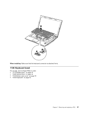
5 7 6 When installing: Make sure that the keyboard connector is attached firmly. 1100 Keyboard bezel For access, remove these FRUs in order: • "1010 Battery pack" on page 44 • "1020 Optical drive" on page 44 • "1030 Bottom slot cover" on page 46 • "1090 Keyboard" on page 54 Chapter 7. Removing and replacing a FRU 57
5 7 6 When installing: Make sure that the keyboard connector is attached firmly. 1100 Keyboard bezel For access, remove these FRUs in order: • "1010 Battery pack" on page 44 • "1020 Optical drive" on page 44 • "1030 Bottom slot cover" on page 46 • "1090 Keyboard" on page 54 Chapter 7. Removing and replacing a FRU 57
Hardware Maintenance Manual - Lenovo E49
Page 65
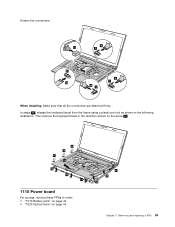
Detach the connectors. 6 13 5 11 8 7 12 10 9 When installing: Make sure that all the connectors are attached firmly. In steps 14 , release the keyboard bezel from the frame using a plastic pry tool as shown in order: • "1010 Battery pack" on page 44 • "1020 Optical drive" on page 44 14 14 14 Chapter 7. Removing and replacing a FRU 59 Then remove the keyboard bezel in the direction shown by the arrow 15 . 14 14 14 15 14 14 14 1110 Power board For access, remove these FRUs in the following illustration.
Detach the connectors. 6 13 5 11 8 7 12 10 9 When installing: Make sure that all the connectors are attached firmly. In steps 14 , release the keyboard bezel from the frame using a plastic pry tool as shown in order: • "1010 Battery pack" on page 44 • "1020 Optical drive" on page 44 14 14 14 Chapter 7. Removing and replacing a FRU 59 Then remove the keyboard bezel in the direction shown by the arrow 15 . 14 14 14 15 14 14 14 1110 Power board For access, remove these FRUs in the following illustration.
Hardware Maintenance Manual - Lenovo E49
Page 66
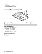
... 1 and then remove the power board 2 . 2 1 2 Step 1 Screw (quantity) M2 × 3 mm, flat-head, nylon-coated (1) 1120 Backup battery For access, remove these FRUs in order: • "1010 Battery pack" on page 44 • "1020 Optical drive" on page 44 • "1030 Bottom slot cover" on page 46 • "1090... Keyboard" on page 54 • "1100 Keyboard bezel" on page 57 Removal steps of backup battery DANGER Color Black Torque 1.85 kgf-cm...
... 1 and then remove the power board 2 . 2 1 2 Step 1 Screw (quantity) M2 × 3 mm, flat-head, nylon-coated (1) 1120 Backup battery For access, remove these FRUs in order: • "1010 Battery pack" on page 44 • "1020 Optical drive" on page 44 • "1030 Bottom slot cover" on page 46 • "1090... Keyboard" on page 54 • "1100 Keyboard bezel" on page 57 Removal steps of backup battery DANGER Color Black Torque 1.85 kgf-cm...


