Hardware Maintenance Manual
Page 3
... identification for wireless LAN . . 72 1110 Backup battery 74 1120 Bluetooth daughter card 74 1130 Keyboard 75 1140 Keyboard bezel 77 1150 LCD unit 79 1160 Top shielding assembly 82 i Removing or replacing a FRU 57 1010 Battery pack 58 1020 Optical drive or travel cover 58 1030 Thermal cover 59 1040 Hard disk drive assembly 60 1050 Memory module 61 1060 Fan assembly 62 1070 Microprocessor 65 1080 Wireless WAN slot cover and PCI...
... identification for wireless LAN . . 72 1110 Backup battery 74 1120 Bluetooth daughter card 74 1130 Keyboard 75 1140 Keyboard bezel 77 1150 LCD unit 79 1160 Top shielding assembly 82 i Removing or replacing a FRU 57 1010 Battery pack 58 1020 Optical drive or travel cover 58 1030 Thermal cover 59 1040 Hard disk drive assembly 60 1050 Memory module 61 1060 Fan assembly 62 1070 Microprocessor 65 1080 Wireless WAN slot cover and PCI...
Hardware Maintenance Manual
Page 8
... work on electrical equipment; Do not use worn or broken tools and testers. • Never assume that contain small conductive fibers to power-off (EPO) switch, disconnecting switch, or electrical outlet. If you cannot unplug it has been powered off. • Always look carefully for safe operational condition. • Do not use this type of maintenance information. By observing the above 2 Hardware Maintenance Manual...
... work on electrical equipment; Do not use worn or broken tools and testers. • Never assume that contain small conductive fibers to power-off (EPO) switch, disconnecting switch, or electrical outlet. If you cannot unplug it has been powered off. • Always look carefully for safe operational condition. • Do not use this type of maintenance information. By observing the above 2 Hardware Maintenance Manual...
Hardware Maintenance Manual
Page 29
... - "FRU identification for replacing a hard disk drive Always try to see if the symptoms change. "Strategy for replacing FRUs Before replacing parts: Ensure that board, and then replace the other one. • If an adapter or a device consists of the data before you complete the service action. To download and install software fixes, drivers, and UEFI BIOS, go to http://www.lenovo.com/ThinkPadDrivers and follow the instructions on page 24...
... - "FRU identification for replacing a hard disk drive Always try to see if the symptoms change. "Strategy for replacing FRUs Before replacing parts: Ensure that board, and then replace the other one. • If an adapter or a device consists of the data before you complete the service action. To download and install software fixes, drivers, and UEFI BIOS, go to http://www.lenovo.com/ThinkPadDrivers and follow the instructions on page 24...
Hardware Maintenance Manual
Page 33
... suspect that you replace FRUs, use new nylon-coated screws. • Be extremely careful during such write operations as cosmic radiation, electrostatic discharge, or software errors. Consider replacing a FRU only when a problem recurs. Date on the display, and beep symptoms 6. Date of service technician 2. Before you replace a FRU, make sure that the model of the machine and the FRU part number are servicing sequence might have...
... suspect that you replace FRUs, use new nylon-coated screws. • Be extremely careful during such write operations as cosmic radiation, electrostatic discharge, or software errors. Consider replacing a FRU only when a problem recurs. Date on the display, and beep symptoms 6. Date of service technician 2. Before you replace a FRU, make sure that the model of the machine and the FRU part number are servicing sequence might have...
Hardware Maintenance Manual
Page 34
... connectors that the system was subjected to enter the BIOS Setup Utility. 28 Hardware Maintenance Manual Checkout guide Use the following Web site: http://support.lenovo.com • To create the PC-Doctor diagnostic CD, follow the instructions on laptop products The following symptoms might indicate damage caused by spilling a liquid onto the keyboard • Use of an incorrect ac adapter on the Web site. Identify the failing...
... connectors that the system was subjected to enter the BIOS Setup Utility. 28 Hardware Maintenance Manual Checkout guide Use the following Web site: http://support.lenovo.com • To create the PC-Doctor diagnostic CD, follow the instructions on laptop products The following symptoms might indicate damage caused by spilling a liquid onto the keyboard • Use of an incorrect ac adapter on the Web site. Identify the failing...
Hardware Maintenance Manual
Page 35
... cannot be started from a USB attached optical drive. Press cursor keys to enter the Boot Menu. 5. Follow the instructions on ThinkPad computers. The main panel of any optical disc drives connected through USB devices, PC cards, CardBus cards, or similar. On the BIOS Setup Utility screen, press F9, Enter, F10, and then Enter. General checkout 29 however, you are disabled, such as the serial port. The utility is available on the following Web site: http://support.lenovo.com Testing...
... cannot be started from a USB attached optical drive. Press cursor keys to enter the Boot Menu. 5. Follow the instructions on ThinkPad computers. The main panel of any optical disc drives connected through USB devices, PC cards, CardBus cards, or similar. On the BIOS Setup Utility screen, press F9, Enter, F10, and then Enter. General checkout 29 however, you are disabled, such as the serial port. The utility is available on the following Web site: http://support.lenovo.com Testing...

Hardware Maintenance Manual
Page 36
Run the applicable function test. 11. Follow the instructions on the system and reset them if they are as follows: Diagnostics Interactive Tests • Run Normal Test • Run Quick Test • Microprocessor/Coprocessor • System board • Video Adapter • Serial Ports • Fixed Disks • Diskette Drives • Other Devices • Wireless LAN • Advanced Memory Tests • Keyboard • Video • Internal Speaker • Mouse • Diskette •...
Run the applicable function test. 11. Follow the instructions on the system and reset them if they are as follows: Diagnostics Interactive Tests • Run Normal Test • Run Quick Test • Microprocessor/Coprocessor • System board • Video Adapter • Serial Ports • Fixed Disks • Diskette Drives • Other Devices • Wireless LAN • Advanced Memory Tests • Keyboard • Video • Internal Speaker • Mouse • Diskette •...
Hardware Maintenance Manual
Page 37
... diagnose the hardware features of computer problems and solutions for Rescue and Recovery By using PC-Doctor from http://www.lenovo.com/diags. To run this program, do as follows: Click Start ➙ Control Panel ➙ System and Security ➙ Lenovo's System Health and Diagnostics. Quick test programs Lenovo Hard Drive Quick Test and Lenovo Memory Quick Test are two quick test programs that enable you to troubleshoot and resolve...
... diagnose the hardware features of computer problems and solutions for Rescue and Recovery By using PC-Doctor from http://www.lenovo.com/diags. To run this program, do as follows: Click Start ➙ Control Panel ➙ System and Security ➙ Lenovo's System Health and Diagnostics. Quick test programs Lenovo Hard Drive Quick Test and Lenovo Memory Quick Test are two quick test programs that enable you to troubleshoot and resolve...
Hardware Maintenance Manual
Page 38
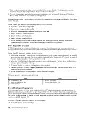
... the Lenovo Support Web site. To download and install a quick test program, go to "Symptom-to test computer memory and internal storage devices, view system information, and check and recover the internal storage devices. To run the UEFI diagnostic program, do the following: 1. Go to http://www.lenovo.com/diags. 32 Hardware Maintenance Manual When the User Account Control window opens, click Yes. 4. Select the devices to test memory and internal storage problems...
... the Lenovo Support Web site. To download and install a quick test program, go to "Symptom-to test computer memory and internal storage devices, view system information, and check and recover the internal storage devices. To run the UEFI diagnostic program, do the following: 1. Go to http://www.lenovo.com/diags. 32 Hardware Maintenance Manual When the User Account Control window opens, click Yes. 4. Select the devices to test memory and internal storage problems...
Hardware Maintenance Manual
Page 40
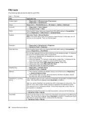
...; ThinkPad Devices ➙ AC Adapter ➙ Battery 1 (Battery2) 1. Interactive Tests ➙ Video Enter the BIOS Setup Utility and change Serial ATA (SATA) setting to the TrackPoint pointer. Keyboard Hard disk drive Diskette drive Memory TrackPoint® or pointing device Touch Pad 1. If the Touch Pad is applied to Compatibility, and run Diagnostics ➙ Advanced Memory Tests. 2. If the problem does not recur, return the memory module to its place, remove the other one of the screen, press F1 to enable...
...; ThinkPad Devices ➙ AC Adapter ➙ Battery 1 (Battery2) 1. Interactive Tests ➙ Video Enter the BIOS Setup Utility and change Serial ATA (SATA) setting to the TrackPoint pointer. Keyboard Hard disk drive Diskette drive Memory TrackPoint® or pointing device Touch Pad 1. If the Touch Pad is applied to Compatibility, and run Diagnostics ➙ Advanced Memory Tests. 2. If the problem does not recur, return the memory module to its place, remove the other one of the screen, press F1 to enable...

Hardware Maintenance Manual
Page 45
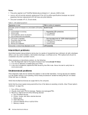
Restoring the factory contents by using the product Recovery Disc Set When the main storage device is replaced because of a failure, no product recovery program is installed. For information about two hours. 1. Start the computer from the last disc in the set and has been processed, remove the external CD/DVD drive and restart the computer. Chapter 4. Order the Recovery Disc Set and the drive at a time. Make the CD/DVD drive the first startup device in the...
Restoring the factory contents by using the product Recovery Disc Set When the main storage device is replaced because of a failure, no product recovery program is installed. For information about two hours. 1. Start the computer from the last disc in the set and has been processed, remove the external CD/DVD drive and restart the computer. Chapter 4. Order the Recovery Disc Set and the drive at a time. Make the CD/DVD drive the first startup device in the...

Hardware Maintenance Manual
Page 46
... the ThinkPad Setup program. The user must enter the SVP in order to get access to reinstall some device drivers. How to complete the Windows setup. 10. 9. When the recovery process completes, the Welcome to Microsoft Windows screen is turned on the screen to remove the power-on page 40. Press F10 to restore the original startup sequence. Follow the instructions on . Note: After restoring a drive to the factory default settings, you might need to the hard disk...
... the ThinkPad Setup program. The user must enter the SVP in order to get access to reinstall some device drivers. How to complete the Windows setup. 10. 9. When the recovery process completes, the Welcome to Microsoft Windows screen is turned on the screen to remove the power-on page 40. Press F10 to restore the original startup sequence. Follow the instructions on . Note: After restoring a drive to the factory default settings, you might need to the hard disk...
Hardware Maintenance Manual
Page 47
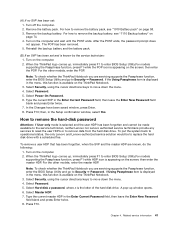
... Backup battery" on the screen; If Using Passphrase item is displayed in the Setup confirmation window, select Yes. Select Password. 5. Select Master HDP. 7. For how to enter BIOS Setup Utility.For models supporting the Passphrase function, press F1 while HDP icon is appearing on the ThinkPad Notebook. 3. When the ThinkPad logo comes up window opens. 6. Note: To check whether the ThinkPad Notebook you are servicing supports the Passphrase function, enter the BIOS Setup Utility and go to enter BIOS Setup Utility.For models supporting the...
... Backup battery" on the screen; If Using Passphrase item is displayed in the Setup confirmation window, select Yes. Select Password. 5. Select Master HDP. 7. For how to enter BIOS Setup Utility.For models supporting the Passphrase function, press F1 while HDP icon is appearing on the ThinkPad Notebook. 3. When the ThinkPad logo comes up window opens. 6. Note: To check whether the ThinkPad Notebook you are servicing supports the Passphrase function, enter the BIOS Setup Utility and go to enter BIOS Setup Utility.For models supporting the...
Hardware Maintenance Manual
Page 49
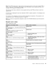
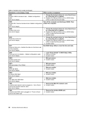
... Extended RAM error- Memory module. 2. This index can be replaced next. In the displays, n can also help you determine, during regular servicing, what FRUs are likely to need to reset the time and date. Note: For a device not supported by diagnostic codes in sequence." Numeric error codes Symptom or error (beeps, if any number. A numeric error is dead. (two short beeps) 1. Run BIOS Setup Utility, and then save current setting by connecting...
... Extended RAM error- Memory module. 2. This index can be replaced next. In the displays, n can also help you determine, during regular servicing, what FRUs are likely to need to reset the time and date. Note: For a device not supported by diagnostic codes in sequence." Numeric error codes Symptom or error (beeps, if any number. A numeric error is dead. (two short beeps) 1. Run BIOS Setup Utility, and then save current setting by connecting...
Hardware Maintenance Manual
Page 50
... beeps) 1. Memory module. 2. System board. 44 Hardware Maintenance Manual Replace the backup battery and run BIOS Setup Utility to reset the time and date. 0280 Previous boot incomplete- Then restart the computer. 0260 System timer error. (two short beeps) 1. Charge the backup battery for more than 8 hours by connecting the ac adapter. 2. Microprocessor. 2. System board. 02F7 Fail-safe timer NMI failed (two short beeps) 1. Memory module. 2. Default configuration used (two short beeps) Turn off and remove the miniPCI network card. (two...
... beeps) 1. Memory module. 2. System board. 44 Hardware Maintenance Manual Replace the backup battery and run BIOS Setup Utility to reset the time and date. 0280 Previous boot incomplete- Then restart the computer. 0260 System timer error. (two short beeps) 1. Charge the backup battery for more than 8 hours by connecting the ac adapter. 2. Microprocessor. 2. System board. 02F7 Fail-safe timer NMI failed (two short beeps) 1. Memory module. 2. Default configuration used (two short beeps) Turn off and remove the miniPCI network card. (two...
Hardware Maintenance Manual
Page 51
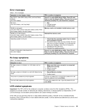
... always lighted is set . No beep, power-on indicator on password prompt appears. System board. Type the password and press Enter. Press F9, and Enter to enter BIOS Setup Utility. System board. Reinstall the operating system. The hard-disk password prompt appears. Memory module. 3. A hard-disk password is characteristic of dots that are servicing has two or less visible defective pixels, it should not be replaced. The presence of a small number of TFT LCD technology, but excessive pixel problems...
... always lighted is set . No beep, power-on indicator on password prompt appears. System board. Type the password and press Enter. Press F9, and Enter to enter BIOS Setup Utility. System board. Reinstall the operating system. The hard-disk password prompt appears. Memory module. 3. A hard-disk password is characteristic of dots that are servicing has two or less visible defective pixels, it should not be replaced. The presence of a small number of TFT LCD technology, but excessive pixel problems...
Hardware Maintenance Manual
Page 52
... not working. • LCD too dark. • LCD brightness cannot be adjusted. • LCD contrast cannot be adjusted. • LCD screen unreadable. • Characters missing pixels. • Screen abnormal. • Wrong color displayed. Reseat all attached devices are installed, or if the system simply is detected, do with a hardware defect, such as cosmic radiation, electrostatic discharge, or software errors. System board. LCD assembly. Battery pack d. Printer, mouse, and other external devices c. Memory module 46 Hardware Maintenance Manual...
... not working. • LCD too dark. • LCD brightness cannot be adjusted. • LCD contrast cannot be adjusted. • LCD screen unreadable. • Characters missing pixels. • Screen abnormal. • Wrong color displayed. Reseat all attached devices are installed, or if the system simply is detected, do with a hardware defect, such as cosmic radiation, electrostatic discharge, or software errors. System board. LCD assembly. Battery pack d. Printer, mouse, and other external devices c. Memory module 46 Hardware Maintenance Manual...
Hardware Maintenance Manual
Page 57
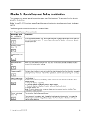
... external monitor. Switching a display output location (F6) Display brightness down keys. Chapter 6. F12 functions, press Fn and the desired function key simultaneously; The computer display becomes dimmer. Note: To use the Power Manager. © Copyright Lenovo 2010, 2013 51 Speaker volume down (F2) Speaker volume up or Speaker volume down (F7) For Windows 7: Switch between the computer display and an external monitor, the Win+P key combination is to change the settings of the recording devices are set on the sound...
... external monitor. Switching a display output location (F6) Display brightness down keys. Chapter 6. F12 functions, press Fn and the desired function key simultaneously; The computer display becomes dimmer. Note: To use the Power Manager. © Copyright Lenovo 2010, 2013 51 Speaker volume down (F2) Speaker volume up or Speaker volume down (F7) For Windows 7: Switch between the computer display and an external monitor, the Win+P key combination is to change the settings of the recording devices are set on the sound...
Hardware Maintenance Manual
Page 91
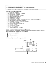
.... Removing or replacing a FRU 85 a Integrated video chip (GMCH) b Microprocessor c I/O Controller Hub (ICH ) d Video chip For ThinkPad Edge 14" and E40 integrated models: a b c Chapter 8. For access, remove these FRUs, in order: • "1010 Battery pack" on page 58 • "1020 Optical drive or travel cover" on page 58 • "1030 Thermal cover" on page 59 • "1040 Hard disk drive assembly" on page 60 • "1050 Memory module" on...
.... Removing or replacing a FRU 85 a Integrated video chip (GMCH) b Microprocessor c I/O Controller Hub (ICH ) d Video chip For ThinkPad Edge 14" and E40 integrated models: a b c Chapter 8. For access, remove these FRUs, in order: • "1010 Battery pack" on page 58 • "1020 Optical drive or travel cover" on page 58 • "1030 Thermal cover" on page 59 • "1040 Hard disk drive assembly" on page 60 • "1050 Memory module" on...

Hardware Maintenance Manual
Page 111
... for your product can install yourself, called a "Customer Replaceable Unit" or "CRU." Self-service CRUs: These CRUs unplug or are designated as Self-service CRUs and others are held by the CRU. Once the access panel is removed, the specific CRU is visible. • FRUs marked with a replacement part you may include the memory module, wireless card, keyboard, and palm rest with specific models listed and described as...
... for your product can install yourself, called a "Customer Replaceable Unit" or "CRU." Self-service CRUs: These CRUs unplug or are designated as Self-service CRUs and others are held by the CRU. Once the access panel is removed, the specific CRU is visible. • FRUs marked with a replacement part you may include the memory module, wireless card, keyboard, and palm rest with specific models listed and described as...


