Hardware Maintenance Manual
Page 3
... Mini Card for Rescue and Recovery . . . . 31 Lenovo Solution Center 31 FRU tests 34 Power system checkout 35 Checking the ac adapter 35 Checking operational charging 35 Checking the battery pack 36 Checking the backup battery 36 Chapter 4. Special keys and Fn key combination 51 Chapter ...service information 39 Restoring the factory contents by using PC-Doctor for DOS. . . . 28 Lenovo ThinkVantage Toolbox (Lenovo System Toolbox 31 PC-Doctor for wireless LAN . . 72 1110 Backup battery 74 1120 Bluetooth daughter card 74 1130 Keyboard 75 1140 Keyboard bezel 77 1150 LCD unit 79 ...
... Mini Card for Rescue and Recovery . . . . 31 Lenovo Solution Center 31 FRU tests 34 Power system checkout 35 Checking the ac adapter 35 Checking operational charging 35 Checking the battery pack 36 Checking the backup battery 36 Chapter 4. Special keys and Fn key combination 51 Chapter ...service information 39 Restoring the factory contents by using PC-Doctor for DOS. . . . 28 Lenovo ThinkVantage Toolbox (Lenovo System Toolbox 31 PC-Doctor for wireless LAN . . 72 1110 Backup battery 74 1120 Bluetooth daughter card 74 1130 Keyboard 75 1140 Keyboard bezel 77 1150 LCD unit 79 ...
Hardware Maintenance Manual
Page 9
... the unit for any obvious unsafe conditions, such as to measure third-wire ground continuity for any non-ThinkPad alterations. 7. Check for cracked or bulging batteries. 5. Chapter 1. Use a meter to the safety of fire or smoke damage. 8. c. Check that are present, you must not be and whether you in identifying potentially...
... the unit for any obvious unsafe conditions, such as to measure third-wire ground continuity for any non-ThinkPad alterations. 7. Check for cracked or bulging batteries. 5. Chapter 1. Use a meter to the safety of fire or smoke damage. 8. c. Check that are present, you must not be and whether you in identifying potentially...
Hardware Maintenance Manual
Page 10
... section are provided in protective packages until they exceed the requirements noted here. 2. Attach the ESD ground clip to eliminate static on a double-insulated or battery-operated system, use have been certified (ISO 9000) as those listed below, to provide protection that the ESD protective devices you are inserted into the...
... section are provided in protective packages until they exceed the requirements noted here. 2. Attach the ESD ground clip to eliminate static on a double-insulated or battery-operated system, use have been certified (ISO 9000) as those listed below, to provide protection that the ESD protective devices you are inserted into the...

Hardware Maintenance Manual
Page 36
... Info • Hardware Events Log • Run External Tests • Surface Scan Hard Disk • Benchmark System • DOS Shell • Tech Support Form • Battery Rundown • View Test Log • Print Log • Save Log • Full Erase Hard Drive • Quick Erase Hard Drive 30 Hardware Maintenance Manual...
... Info • Hardware Events Log • Run External Tests • Surface Scan Hard Disk • Benchmark System • DOS Shell • Tech Support Form • Battery Rundown • View Test Log • Print Log • Save Log • Full Erase Hard Drive • Quick Erase Hard Drive 30 Hardware Maintenance Manual...
Hardware Maintenance Manual
Page 40
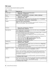
... up the operating system. This symptom is applied to enter the BIOS Setup Utility. 4. Diagnostics ➙ Systemboard Diagnostics ➙ ThinkPad Devices ➙ AC Adapter ➙ Battery 1 (Battery2) 1. Interactive Tests ➙ Diskette 1. FRU tests FRU System board Power LCD unit Audio Speaker Applicable test 1. Interactive Tests ➙ Video Enter the BIOS Setup...
... up the operating system. This symptom is applied to enter the BIOS Setup Utility. 4. Diagnostics ➙ Systemboard Diagnostics ➙ ThinkPad Devices ➙ AC Adapter ➙ Battery 1 (Battery2) 1. Interactive Tests ➙ Diskette 1. FRU tests FRU System board Power LCD unit Audio Speaker Applicable test 1. Interactive Tests ➙ Video Enter the BIOS Setup...
Hardware Maintenance Manual
Page 41
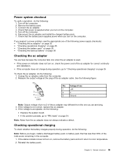
... to "Checking operational charging" on page 35 To check the ac adapter, do the following: Note: Before you begin, install a discharged battery pack or battery pack that has less than 50% of the ac adapter may different from the one you suspect a power problem, see the appropriate one of...to "FRU tests" on page 34. If the status indicator does not turn on the computer. 5. Disconnect the ac adapter and install the charged battery pack. 7. Check that power is acceptable, do the following : 1. If the voltage is supplied when you turn on the computer. General checkout 35...
... to "Checking operational charging" on page 35 To check the ac adapter, do the following: Note: Before you begin, install a discharged battery pack or battery pack that has less than 50% of the ac adapter may different from the one you suspect a power problem, see the appropriate one of...to "FRU tests" on page 34. If the status indicator does not turn on the computer. 5. Disconnect the ac adapter and install the charged battery pack. 7. Check that power is acceptable, do the following : 1. If the voltage is supplied when you turn on the computer. General checkout 35...
Hardware Maintenance Manual
Page 42
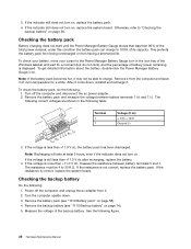
...for a moment (but do the following figure. 36 Hardware Maintenance Manual The resistance must be able to "Checking the backup battery" on , replace the battery pack. 4. Remove the backup battery (see "1010 Battery pack" on . See the following : 1. If the indicator still does not turn on page 74). 5. under this...the ac power adapter. 2. If the resistance is correct, replace the system board. If the resistance is not correct, replace the battery pack. To check your battery, move your cursor to 30 K Ω. Remove it from the computer and leave it may not be 4 to the Power ...
...for a moment (but do the following figure. 36 Hardware Maintenance Manual The resistance must be able to "Checking the backup battery" on , replace the battery pack. 4. Remove the backup battery (see "1010 Battery pack" on . See the following : 1. If the indicator still does not turn on page 74). 5. under this...the ac power adapter. 2. If the resistance is correct, replace the system board. If the resistance is not correct, replace the battery pack. To check your battery, move your cursor to 30 K Ω. Remove it from the computer and leave it may not be 4 to the Power ...
Hardware Maintenance Manual
Page 43
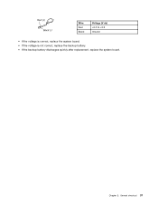
General checkout 37 Wire Red Black Voltage (V dc) +2.5 to +3.2 Ground • If the voltage is correct, replace the system board. • If the voltage is not correct, replace the backup battery. • If the backup battery discharges quickly after replacement, replace the system board. Chapter 3.
General checkout 37 Wire Red Black Voltage (V dc) +2.5 to +3.2 Ground • If the voltage is correct, replace the system board. • If the voltage is not correct, replace the backup battery. • If the backup battery discharges quickly after replacement, replace the system board. Chapter 3.
Hardware Maintenance Manual
Page 47
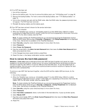
... put the system back to operational status, the only Lenovo and Lenovo-authorized service solution would be made available to the service technician, neither Lenovo nor Lenovo authorized service technicians provide any services to reset the user HDPs or to remove the backup battery, see "1010 Battery pack" on the screen; Type the current master HDP...
... put the system back to operational status, the only Lenovo and Lenovo-authorized service solution would be made available to the service technician, neither Lenovo nor Lenovo authorized service technicians provide any services to reset the user HDPs or to remove the backup battery, see "1010 Battery pack" on the screen; Type the current master HDP...
Hardware Maintenance Manual
Page 48
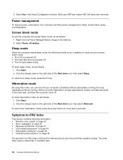
... right side of the Shut down icon; To return from hibernation mode, press the power button for more than 4 seconds. Right-click the Power Manager Battery Gauge in boldface type. 42 Hardware Maintenance Manual To enter sleep mode, do as follows: 1. Click Start. 2. To enter hibernation mode, do as follows: 1. To...
... right side of the Shut down icon; To return from hibernation mode, press the power button for more than 4 seconds. Right-click the Power Manager Battery Gauge in boldface type. 42 Hardware Maintenance Manual To enter sleep mode, do as follows: 1. Click Start. 2. To enter hibernation mode, do as follows: 1. To...
Hardware Maintenance Manual
Page 49
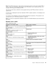
...Change requested. 1. System board. 0232 Extended RAM error- Numeric error codes Symptom or error (beeps, if any number. Charge the battery pack. 2. Charge the backup battery for more than 8 hours by pressing F10. 2. Chapter 4. Related service information 43 A numeric error is displayed for each error... RAM fails at offset nnnn. (two short beeps) 1. Extended RAM fails at offset nnnn. (two short beeps) 1. Replace the backup battery and run BIOS Setup Utility to EEPROM is failed. (two short beeps) 0189 Invalid RFID configuration information area-The EEPROM checksum is dead....
...Change requested. 1. System board. 0232 Extended RAM error- Numeric error codes Symptom or error (beeps, if any number. Charge the battery pack. 2. Charge the backup battery for more than 8 hours by pressing F10. 2. Chapter 4. Related service information 43 A numeric error is displayed for each error... RAM fails at offset nnnn. (two short beeps) 1. Extended RAM fails at offset nnnn. (two short beeps) 1. Replace the backup battery and run BIOS Setup Utility to EEPROM is failed. (two short beeps) 0189 Invalid RFID configuration information area-The EEPROM checksum is dead....
Hardware Maintenance Manual
Page 50
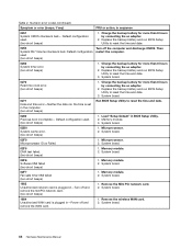
.... 2. System board. 02F0 Microprocessor ID:xx Failed. 1. System board. 02F6 Software NMI failed (two short beeps) 1. Replace the backup battery and run BIOS Setup Utility to reset the time and date. 0280 Previous boot incomplete- System board. 02F5 DMA test failed. (two short.... (two short beeps) 1. Microprocessor. 2. Microprocessor. 2. Memory module. 2. Memory module. 2. Remove the wireless WAN card. 2. Replace the backup battery and run BIOS Setup Utility to reset the time and date. 3. System board. 0271 Date and time error-Neither the date nor the time is...
.... 2. System board. 02F0 Microprocessor ID:xx Failed. 1. System board. 02F6 Software NMI failed (two short beeps) 1. Replace the backup battery and run BIOS Setup Utility to reset the time and date. 0280 Previous boot incomplete- System board. 02F5 DMA test failed. (two short.... (two short beeps) 1. Microprocessor. 2. Microprocessor. 2. Memory module. 2. Memory module. 2. Remove the wireless WAN card. 2. Replace the backup battery and run BIOS Setup Utility to reset the time and date. 3. System board. 0271 Date and time error-Neither the date nor the time is...
Hardware Maintenance Manual
Page 52
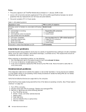
...System board. 1. Replace any replacement LCD will not provide warranty replacement if the LCD is detected, replace the FRU shown by the computer. Battery pack d. Table 5. FRU replacement should be adjusted. • LCD screen unreadable. • Characters missing pixels. • Screen abnormal....drive f. System board. 1. Notes: • This policy applies to all ThinkPad Notebooks purchased on 1 January, 2008 or later. • Lenovo will have zero pixel defects. • One pixel consists of the failure is detected, do not replace any FRUs. 3. LCD-related symptoms...
...System board. 1. Replace any replacement LCD will not provide warranty replacement if the LCD is detected, replace the FRU shown by the computer. Battery pack d. Table 5. FRU replacement should be adjusted. • LCD screen unreadable. • Characters missing pixels. • Screen abnormal....drive f. System board. 1. Notes: • This policy applies to all ThinkPad Notebooks purchased on 1 January, 2008 or later. • Lenovo will have zero pixel defects. • One pixel consists of the failure is detected, do not replace any FRUs. 3. LCD-related symptoms...
Hardware Maintenance Manual
Page 55
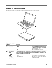
If a battery is installed on the computer, it shows whether the computer is on . The ac adapter is connected. Red: Fast blinking red: The computer is in ... and on the palm rest works as a system-status indicator: it is charged when this indicator is entering sleep (standby) or hibernation mode. © Copyright Lenovo 2010, 2013 49 The computer is on (in sleep (standby), hibernation, or normal model.
If a battery is installed on the computer, it shows whether the computer is on . The ac adapter is connected. Red: Fast blinking red: The computer is in ... and on the palm rest works as a system-status indicator: it is charged when this indicator is entering sleep (standby) or hibernation mode. © Copyright Lenovo 2010, 2013 49 The computer is on (in sleep (standby), hibernation, or normal model.
Hardware Maintenance Manual
Page 63
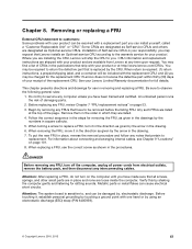
Where you are available from electrical outlets, remove the battery pack, and then disconnect any FRU, review Chapter 7 "FRU replacement notices" on page 101. 8. You may request that Lenovo installs an Optional-service CRU according to you may find a list of CRUs in the ...until you can cause electrical short circuits. When return is replaced by using an electrostatic discharge (ESD) strap (P/N 6405959). © Copyright Lenovo 2010, 2013 57 Some CRUs are designated as Optional-service CRUs. When removing the FRU, move it , establish personal grounding by touching ...
Where you are available from electrical outlets, remove the battery pack, and then disconnect any FRU, review Chapter 7 "FRU replacement notices" on page 101. 8. You may request that Lenovo installs an Optional-service CRU according to you may find a list of CRUs in the ...until you can cause electrical short circuits. When return is replaced by using an electrostatic discharge (ESD) strap (P/N 6405959). © Copyright Lenovo 2010, 2013 57 Some CRUs are designated as Optional-service CRUs. When removing the FRU, move it , establish personal grounding by touching ...
Hardware Maintenance Manual
Page 64
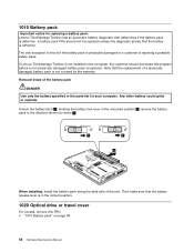
... unless this diagnostic shows that the replacement of the battery pack DANGER Use only the battery specified in the parts list for replacing a battery pack: Lenovo ThinkVantage Toolbox has an automatic battery diagnostic that the battery release lever is not covered by arrow 3 . 1 2 3 When installing: Install the battery pack along the slide rails of the slot. Removal...
... unless this diagnostic shows that the replacement of the battery pack DANGER Use only the battery specified in the parts list for replacing a battery pack: Lenovo ThinkVantage Toolbox has an automatic battery diagnostic that the battery release lever is not covered by arrow 3 . 1 2 3 When installing: Install the battery pack along the slide rails of the slot. Removal...
Hardware Maintenance Manual
Page 65
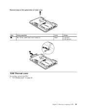
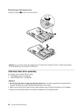
Removal steps of the optical drive or travel cover 1 Step 1 Screw (quantity) M2 × 8 mm, wafer-head, nylon-coated (1) 2 3 Color Black Torque 0.181 Nm (1.85 kgf-cm) 1030 Thermal cover For access, remove this FRU: • "1010 Battery pack" on page 58 Chapter 8. Removing or replacing a FRU 59
Removal steps of the optical drive or travel cover 1 Step 1 Screw (quantity) M2 × 8 mm, wafer-head, nylon-coated (1) 2 3 Color Black Torque 0.181 Nm (1.85 kgf-cm) 1030 Thermal cover For access, remove this FRU: • "1010 Battery pack" on page 58 Chapter 8. Removing or replacing a FRU 59
Hardware Maintenance Manual
Page 66
... mulfunction. 1040 Hard disk drive assembly For access, remove these FRUs in suspend mode. 60 Hardware Maintenance Manual The drive is in order: • "1010 Battery pack" on page 58 • "1030 Thermal cover" on it if possible. • Never remove the drive while the computer is operating or is sensitive...
... mulfunction. 1040 Hard disk drive assembly For access, remove these FRUs in suspend mode. 60 Hardware Maintenance Manual The drive is in order: • "1010 Battery pack" on page 58 • "1030 Thermal cover" on it if possible. • Never remove the drive while the computer is operating or is sensitive...
Hardware Maintenance Manual
Page 67
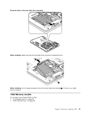
Removing or replacing a FRU 61 To do so, you might bend or break it. 1050 Memory module For access, remove these FRUs in order: • "1010 Battery pack" on page 58 • "1030 Thermal cover" on page 59 Chapter 8. Removal steps of the hard disk drive assembly 1 When installing: Make sure that the hard disk drive connector is attached firmly. 2 a When installing: Do not apply excessive force to the hard disk drive bracket a .
Removing or replacing a FRU 61 To do so, you might bend or break it. 1050 Memory module For access, remove these FRUs in order: • "1010 Battery pack" on page 58 • "1030 Thermal cover" on page 59 Chapter 8. Removal steps of the hard disk drive assembly 1 When installing: Make sure that the hard disk drive connector is attached firmly. 2 a When installing: Do not apply excessive force to the hard disk drive bracket a .
Hardware Maintenance Manual
Page 68
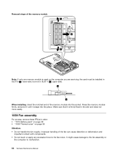
... until it is used on the computer you are servicing, the card must be installed in SLOT-0 ( a : lower slot), but not in order: • "1010 Battery pack" on page 58 • "1030 Thermal cover" on page 59 Attention: • Do not handle the fan roughly. It might cause damage to the...
... until it is used on the computer you are servicing, the card must be installed in SLOT-0 ( a : lower slot), but not in order: • "1010 Battery pack" on page 58 • "1030 Thermal cover" on page 59 Attention: • Do not handle the fan roughly. It might cause damage to the...


