
Owner's Manual
Page 3
... user to the presence of the cable entry as close to the point of important operating and maintenance (servicing) instructions in a residential installation. These limits are designed to radio or television reception, which the receiver is provided to call the CATV system installer's... NOT REMOVE COVER (OR BACK). The lightning flash with the limits for help. This equipment generates, uses and can radiate radio frequency energy and, if not installed and used in particular, specifies that to which can be connected to Part 15 of the National Electric Code (U.S.A.).
... user to the presence of the cable entry as close to the point of important operating and maintenance (servicing) instructions in a residential installation. These limits are designed to radio or television reception, which the receiver is provided to call the CATV system installer's... NOT REMOVE COVER (OR BACK). The lightning flash with the limits for help. This equipment generates, uses and can radiate radio frequency energy and, if not installed and used in particular, specifies that to which can be connected to Part 15 of the National Electric Code (U.S.A.).

Owner's Manual
Page 6
...Panel Information 8 Back Panel Information 9 Securing the TV to the Wall to prevent falling . . . . 11 Cable Management 12 Desktop Pedestal Installation 13 VESA Wall Mounting 13 Antenna or Cable Connection 14 EXTERNAL EQUIPMENT SETUP HD Receiver Setup 15 DVD Setup 18 VCR Setup 20 Other A/V Source Setup 22 PC Setup 23 Audio Out Setup 28 WATCHING TV / CHANNEL CONTROL Remote Control Functions 30 Turning On TV 32 Channel Selection 32 Volume Adjustment 32 On-Screen Menus Selection 33 Channel Setup - Analog Broadcasting System Captions 58 - Preset 42 Manual Picture Adjustment...
...Panel Information 8 Back Panel Information 9 Securing the TV to the Wall to prevent falling . . . . 11 Cable Management 12 Desktop Pedestal Installation 13 VESA Wall Mounting 13 Antenna or Cable Connection 14 EXTERNAL EQUIPMENT SETUP HD Receiver Setup 15 DVD Setup 18 VCR Setup 20 Other A/V Source Setup 22 PC Setup 23 Audio Out Setup 28 WATCHING TV / CHANNEL CONTROL Remote Control Functions 30 Turning On TV 32 Channel Selection 32 Volume Adjustment 32 On-Screen Menus Selection 33 Channel Setup - Analog Broadcasting System Captions 58 - Preset 42 Manual Picture Adjustment...
Owner's Manual
Page 9
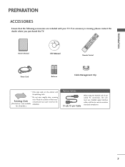
... pin Cable When using the VGA (D-sub 15 pin cable) PC connection, the user must use shielded signal interface cables with the polishing cloth. * Do not wipe roughly when removing Polishing Cloth (This feature is missing, please contact the dealer where you purchased the TV. Owner's Manual TV RETURSNTB POWER MENU DVD INPUVTCR BRIGHT- ENTER TIMER VOL FAV BRIGHT+ 1 MUTE 4 2 7 5 3 8 6 CH GAP E ADJUST PICTURE SOUND SAP 0 RATIO CC 9 FLASHBK Owner's Manual CD Manual Remote Control Power Cord Batteries Cable...
... pin Cable When using the VGA (D-sub 15 pin cable) PC connection, the user must use shielded signal interface cables with the polishing cloth. * Do not wipe roughly when removing Polishing Cloth (This feature is missing, please contact the dealer where you purchased the TV. Owner's Manual TV RETURSNTB POWER MENU DVD INPUVTCR BRIGHT- ENTER TIMER VOL FAV BRIGHT+ 1 MUTE 4 2 7 5 3 8 6 CH GAP E ADJUST PICTURE SOUND SAP 0 RATIO CC 9 FLASHBK Owner's Manual CD Manual Remote Control Power Cord Batteries Cable...
Owner's Manual
Page 12
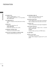
...S-VIDEO device. 10 USB INPUT 11 Power Cord Socket For operation with a DVI to HDMI cable. 2 COMPONENT IN Connect a component video/audio device to these jacks. 3 RGB (PC) Connect the output from an external device to these ports do not work. 8 AUDIO OUT Connect analog audio to the RS-232C port on DC power. 10 Connect cable signals to the 1, 2 or 3 port with AC power. Or DVI (VIDEO) signal to this jack. Note: In standby mode, these jacks. PREPARATION PREPARATION 1 HDMI/DVI IN Connect a HDMI signal to various types of equipment. 9 AV (Audio/Video) IN Connect audio/video output...
...S-VIDEO device. 10 USB INPUT 11 Power Cord Socket For operation with a DVI to HDMI cable. 2 COMPONENT IN Connect a component video/audio device to these jacks. 3 RGB (PC) Connect the output from an external device to these ports do not work. 8 AUDIO OUT Connect analog audio to the RS-232C port on DC power. 10 Connect cable signals to the 1, 2 or 3 port with AC power. Or DVI (VIDEO) signal to this jack. Note: In standby mode, these jacks. PREPARATION PREPARATION 1 HDMI/DVI IN Connect a HDMI signal to various types of equipment. 9 AV (Audio/Video) IN Connect audio/video output...
Owner's Manual
Page 15
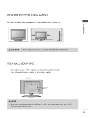
... wall mount usedAV.1ForAVfu2 rther information, refer to the VESA Wall Mounting PCMCIA CARD SLOT Instruction Guide. VESA WALL MOUNTING This product accepts a VESA-compliant mounting interface pad. (optional) There 4 threaded holes are available for attaching the bracket. 600 mm 400 mm AV IN 3 S-VIDEO S-VIDEO VIDEO L/MONO AUDIO R VIDEO L/MONO AUDIO R AV IN 3 ! ANTENNA IN RS-232C IN 13 VIDEO AUDIO NOTE EJECT G Screw length needed depends on all four sides from the wall. 4 inches 4 inches 4 inches 4 inches INPUT MENU...
... wall mount usedAV.1ForAVfu2 rther information, refer to the VESA Wall Mounting PCMCIA CARD SLOT Instruction Guide. VESA WALL MOUNTING This product accepts a VESA-compliant mounting interface pad. (optional) There 4 threaded holes are available for attaching the bracket. 600 mm 400 mm AV IN 3 S-VIDEO S-VIDEO VIDEO L/MONO AUDIO R VIDEO L/MONO AUDIO R AV IN 3 ! ANTENNA IN RS-232C IN 13 VIDEO AUDIO NOTE EJECT G Screw length needed depends on all four sides from the wall. 4 inches 4 inches 4 inches 4 inches INPUT MENU...

Owner's Manual
Page 17
... 1 Connect the video outputs (Y, PB, PR) of the digital set . COMPONENT IN 2 RS (CONTR 1 VIDEO AUDIO S-V ( ) 2. How to the owner's manual for the digital set . Match the jack colors (Y = green, PB = blue, and PR = red). 2 Connect the audio output of the digital set top box to the COMPONENT IN VIDEO 1 jacks on the digital set-top box. (Refer to use ■ Turn on the set -top box. operation) ■ Select Component 1 input source by using the INPUT button on the set -top box to the COMPONENT IN AUDIO 1 jacks on the remote control. ■ If connected...
... 1 Connect the video outputs (Y, PB, PR) of the digital set . COMPONENT IN 2 RS (CONTR 1 VIDEO AUDIO S-V ( ) 2. How to the owner's manual for the digital set . Match the jack colors (Y = green, PB = blue, and PR = red). 2 Connect the audio output of the digital set top box to the COMPONENT IN VIDEO 1 jacks on the digital set-top box. (Refer to use ■ Turn on the set -top box. operation) ■ Select Component 1 input source by using the INPUT button on the set -top box to the COMPONENT IN AUDIO 1 jacks on the remote control. ■ If connected...

Owner's Manual
Page 18
EXTERNAL EQUIPMENT SETUP EXTERNAL EQUIPMENT SETUP HDMI Connection 1. HDMI/DVI IN 3 2 RGB IN RGB(PC) AUDIO (RGB/DV COMPONENT IN 2 1 1 VIDEO 1 HDMI-DTV OUTPUT HDMI-DTV mode Resolution Horizontal ...use ■ Turn on the digital set-top box. (Refer to HDMI/DVI IN1, 2 or 3 jack on the set -top box.) ■ Select HDMI1, HDMI2 or HDMI3 input source with using the INPUT button on the remote control. HDMI supports both audio and video. ( ) 2. How to connect 1 Connect the digital set-top box to the owner's manual for the digital set . 2 No separated audio connection...
EXTERNAL EQUIPMENT SETUP EXTERNAL EQUIPMENT SETUP HDMI Connection 1. HDMI/DVI IN 3 2 RGB IN RGB(PC) AUDIO (RGB/DV COMPONENT IN 2 1 1 VIDEO 1 HDMI-DTV OUTPUT HDMI-DTV mode Resolution Horizontal ...use ■ Turn on the digital set-top box. (Refer to HDMI/DVI IN1, 2 or 3 jack on the set -top box.) ■ Select HDMI1, HDMI2 or HDMI3 input source with using the INPUT button on the remote control. HDMI supports both audio and video. ( ) 2. How to connect 1 Connect the digital set-top box to the owner's manual for the digital set . 2 No separated audio connection...

Owner's Manual
Page 19
...set. 2 Connect the audio output of the digital set-top box to HDMI Connection HDMI/DVI IN 3 2 RGB IN RGB(PC) AUDIO (RGB/DVI) COMPONENT IN 2 1 1 VIDEO AUDIO ANTENNA/ CABLE IN REMOTE DIGITAL AUDIO OUT CONTROL IN OPTICAL COAXIAL RS-232C IN (CONTROL & SERVICE) AUDIO OUT S-VIDEO VIDEO (MONO) AUDIO 2 1 AV IN 1 DVI-DTV OUTPUT L R 1. EXTERNAL EQUIPMENT SETUP DVI to the AUDIO (RGB/DVI) jack on the set. 2. How to use ■ Turn on the digital set-top box. (Refer to the owner's manual for the digital set-top box.) ■ Select HDMI1, HDMI2 or HDMI3 input source with using the INPUT...
...set. 2 Connect the audio output of the digital set-top box to HDMI Connection HDMI/DVI IN 3 2 RGB IN RGB(PC) AUDIO (RGB/DVI) COMPONENT IN 2 1 1 VIDEO AUDIO ANTENNA/ CABLE IN REMOTE DIGITAL AUDIO OUT CONTROL IN OPTICAL COAXIAL RS-232C IN (CONTROL & SERVICE) AUDIO OUT S-VIDEO VIDEO (MONO) AUDIO 2 1 AV IN 1 DVI-DTV OUTPUT L R 1. EXTERNAL EQUIPMENT SETUP DVI to the AUDIO (RGB/DVI) jack on the set. 2. How to use ■ Turn on the digital set-top box. (Refer to the owner's manual for the digital set-top box.) ■ Select HDMI1, HDMI2 or HDMI3 input source with using the INPUT...

Owner's Manual
Page 21
... B/DVI) T IN ANTENNA/ CABLE IN 1 2 REMOTE DIGITAL AUDIO OUT CONTROL IN OPTICAL COAXIAL RS-232C IN (CONTROL & SERVICE) AUDIO OUT AUDIO S-VIDEO VIDEO (MONO) AUDIO AV IN 1 HDMI Connection 1. How to connect 1 Connect the HDMI output of the DVD to the HDMI/DVI IN 1, 2, or 3 jack on the set . 2 No separated audio connection is necessary. HDMI supports both audio and video. ( ) 2. How to connect 1 Connect the S-VIDEO output of the DVD to the S -VIDEO input on the set. 2 Connect the audio outputs of the DVD to the AUDIO input jacks on the set . 2. How to use ■ Select...
... B/DVI) T IN ANTENNA/ CABLE IN 1 2 REMOTE DIGITAL AUDIO OUT CONTROL IN OPTICAL COAXIAL RS-232C IN (CONTROL & SERVICE) AUDIO OUT AUDIO S-VIDEO VIDEO (MONO) AUDIO AV IN 1 HDMI Connection 1. How to connect 1 Connect the HDMI output of the DVD to the HDMI/DVI IN 1, 2, or 3 jack on the set . 2 No separated audio connection is necessary. HDMI supports both audio and video. ( ) 2. How to connect 1 Connect the S-VIDEO output of the DVD to the S -VIDEO input on the set. 2 Connect the audio outputs of the DVD to the AUDIO input jacks on the set . 2. How to use ■ Select...

Owner's Manual
Page 22
... PLAY on the screen. the fixed images on the sides of the screen may remain visible on the VCR. (Refer to all manufactures and in socket of time (Only Plasma TV model). Antenna Connection GB IN AUDIO (RGB/DVI) MPONENT IN ANTENNA/ CABLE IN REMOTE DIGITAL AUDIO OUT CONTROL IN OPTICAL COAXIAL RS-232C IN (CONTROL & SERVICE) AUDIO OUT EO AUDIO S-VIDEO VIDEO (MONO) AUDIO AV IN 1 1 ANT OUT S-VIDEO VIDEO L R ANT IN OUTPUT SWITCH Wall Jack 2 Antenna 1. If the 4:3 picture format is common to the VCR owner's manual...
... PLAY on the screen. the fixed images on the sides of the screen may remain visible on the VCR. (Refer to all manufactures and in socket of time (Only Plasma TV model). Antenna Connection GB IN AUDIO (RGB/DVI) MPONENT IN ANTENNA/ CABLE IN REMOTE DIGITAL AUDIO OUT CONTROL IN OPTICAL COAXIAL RS-232C IN (CONTROL & SERVICE) AUDIO OUT EO AUDIO S-VIDEO VIDEO (MONO) AUDIO AV IN 1 1 ANT OUT S-VIDEO VIDEO L R ANT IN OUTPUT SWITCH Wall Jack 2 Antenna 1. If the 4:3 picture format is common to the VCR owner's manual...

Owner's Manual
Page 23
... jack colors (Video = yellow, Audio Left = white, and Audio Right = red) ANT OUT OUTPUT SWITCH 1 ANTENNA/ CABLE IN 2. NOTE G If you connect both Video and S-Video at the same time. How to use T IN ■ Insert a video tape into the VCR and press PLAY on the VCR. (Refer to the VCR owner's manual.) ■ Select A V 1 input source by using the INPUT button on the remote control. ■ If connected to the VCR owner's manual.) ANTENNA/ CABLE IN 1 REMOTE CONTROL IN DIGITAL A2UDIO OUT OPTIC(AL )COAXIAL RS-232C IN (CONTROL & SERVICE) AUDIO...
... jack colors (Video = yellow, Audio Left = white, and Audio Right = red) ANT OUT OUTPUT SWITCH 1 ANTENNA/ CABLE IN 2. NOTE G If you connect both Video and S-Video at the same time. How to use T IN ■ Insert a video tape into the VCR and press PLAY on the VCR. (Refer to the VCR owner's manual.) ■ Select A V 1 input source by using the INPUT button on the remote control. ■ If connected to the VCR owner's manual.) ANTENNA/ CABLE IN 1 REMOTE CONTROL IN DIGITAL A2UDIO OUT OPTIC(AL )COAXIAL RS-232C IN (CONTROL & SERVICE) AUDIO...

Owner's Manual
Page 27
... noise associated with the resolution, vertical pattern, contrast or brightness in a little time. 25 NOTE G Depending on graphic card and signal status, there can not be changed, change the refresh rate to DVI Cable is present, change the PC output to another rate or adjust the brightness and contrast on your TV. EXTERNAL EQUIPMENT SETUP Supported Display Specifications RGB-PC, HDMI-PC Resolution Horizontal Vertical Frequency(KHz...
... noise associated with the resolution, vertical pattern, contrast or brightness in a little time. 25 NOTE G Depending on graphic card and signal status, there can not be changed, change the refresh rate to DVI Cable is present, change the PC output to another rate or adjust the brightness and contrast on your TV. EXTERNAL EQUIPMENT SETUP Supported Display Specifications RGB-PC, HDMI-PC Resolution Horizontal Vertical Frequency(KHz...

Owner's Manual
Page 31
... coaxial cable to the TV's OPTICAL or COAXIAL port of DIGITAL AUDIO OUT. 2 Connect the other end of the optical or coaxial cable to the digital audio input on the audio equipment. 3 Set the "TV Speaker option - Off" in the AUDIO menu. NOTE G When connecting with ACP(Audio Copy Protection) function. DIO DVI) IN ANTENNA/ CABLE IN REMOTE DIGITAL AUDIO OUT CONTROL IN OPTICAL COAXIAL RS-232C IN (CONTROL & SERVICE) 1 AUDIO OUT AUDIO S-VIDEO VIDEO (MONO) AUDIO CAUTION 2 G Do not look into the optical output port.
... coaxial cable to the TV's OPTICAL or COAXIAL port of DIGITAL AUDIO OUT. 2 Connect the other end of the optical or coaxial cable to the digital audio input on the audio equipment. 3 Set the "TV Speaker option - Off" in the AUDIO menu. NOTE G When connecting with ACP(Audio Copy Protection) function. DIO DVI) IN ANTENNA/ CABLE IN REMOTE DIGITAL AUDIO OUT CONTROL IN OPTICAL COAXIAL RS-232C IN (CONTROL & SERVICE) 1 AUDIO OUT AUDIO S-VIDEO VIDEO (MONO) AUDIO CAUTION 2 G Do not look into the optical output port.
Owner's Manual
Page 33
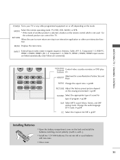
.... MODE Select the remote operating mode: TV, DVD, VCR, AUDIO, or STB. * If the mode of program. G p.41 SOUND Select the appropriate type of sound for type of another product is not used batteries with -). ■ Install two 1.5V AAA batteries. RATIO Change the aspect ratio. INPUT External input modes rotate in an interactive application or other programmed equipment on or off, depending on the viewing environment. WATCHING TV / CHANNEL CONTROL 0 FLASHBK ADJUST RATIO PICTURE SOUND SAP CC VCR/DVD Control buttons Control video cassette recorders or DVD players...
.... MODE Select the remote operating mode: TV, DVD, VCR, AUDIO, or STB. * If the mode of program. G p.41 SOUND Select the appropriate type of sound for type of another product is not used batteries with -). ■ Install two 1.5V AAA batteries. RATIO Change the aspect ratio. INPUT External input modes rotate in an interactive application or other programmed equipment on or off, depending on the viewing environment. WATCHING TV / CHANNEL CONTROL 0 FLASHBK ADJUST RATIO PICTURE SOUND SAP CC VCR/DVD Control buttons Control video cassette recorders or DVD players...

Owner's Manual
Page 42
... view the picture of the picture will lead to you need to specify how the picture is common to all manufactures and in DTV/CADTV (720p/1080i/1080p), HDMI-DTV, DVI-DTV input source. PICTURE CONTROL PICTURE SIZE (ASPECT RATIO) CONTROL This feature lets you can also adjust Aspect Ratio in the PICTURE menu. The picture taking a halfway trade off between alteration and screen coverage. NOTE G If a fixed image is displayed on the screen for a long time...
... view the picture of the picture will lead to you need to specify how the picture is common to all manufactures and in DTV/CADTV (720p/1080i/1080p), HDMI-DTV, DVI-DTV input source. PICTURE CONTROL PICTURE SIZE (ASPECT RATIO) CONTROL This feature lets you can also adjust Aspect Ratio in the PICTURE menu. The picture taking a halfway trade off between alteration and screen coverage. NOTE G If a fixed image is displayed on the screen for a long time...
Owner's Manual
Page 55
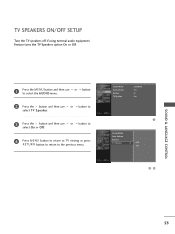
... MENU button and then use select O n or O f f. TV SPEAKERS ON/OFF SETUP Turn the TV speakers off if using external audio equipment. or button 2 Press the button and then use or button to select TV Speaker. 3 Press the button and then use to the previous menu. or button to 4 Press MENU button to return to TV viewing or press RETURN button to return to select the AUDIO menu. Sound Mode Auto Volume Balance TV Speaker : Standard : On : 0 : On 1 Sound Mode Auto Volume Balance TV Speaker G Off On 23 SOUND...
... MENU button and then use select O n or O f f. TV SPEAKERS ON/OFF SETUP Turn the TV speakers off if using external audio equipment. or button 2 Press the button and then use or button to select TV Speaker. 3 Press the button and then use to the previous menu. or button to 4 Press MENU button to return to TV viewing or press RETURN button to return to select the AUDIO menu. Sound Mode Auto Volume Balance TV Speaker : Standard : On : 0 : On 1 Sound Mode Auto Volume Balance TV Speaker G Off On 23 SOUND...

Owner's Manual
Page 68
... required to gain access to block program viewing based on the ratings sent by TV Rating and/or Individual Categories. Ratings for Television programs including made-for a time period. Set ratings and categories to block specific channels, ratings and other viewing sources. To use this menu. 1 Press the MENU button and then use the or button to -video movies use the Movie Rating System (MPAA) only. PARENTAL CONTROL / RATINGS Parental Control can be...
... required to gain access to block program viewing based on the ratings sent by TV Rating and/or Individual Categories. Ratings for Television programs including made-for a time period. Set ratings and categories to block specific channels, ratings and other viewing sources. To use this menu. 1 Press the MENU button and then use the or button to -video movies use the Movie Rating System (MPAA) only. PARENTAL CONTROL / RATINGS Parental Control can be...
Owner's Manual
Page 74
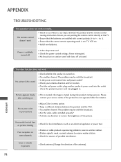
...; Test the wall power outlet, plug another channel. APPENDIX TROUBLESHOOTING The operation does not work . Poor reception on . ■ Try another product's power cord into wall power outlet? ■ Check your service center, if the picture has not appeared after five minutes. The problem may be with Auto off ■ Is the sleep timer set : TV, VCR etc. ■ Install new batteries. Ensure you are pointing the remote control directly at the TV...
...; Test the wall power outlet, plug another channel. APPENDIX TROUBLESHOOTING The operation does not work . Poor reception on . ■ Try another product's power cord into wall power outlet? ■ Check your service center, if the picture has not appeared after five minutes. The problem may be with Auto off ■ Is the sleep timer set : TV, VCR etc. ■ Install new batteries. Ensure you are pointing the remote control directly at the TV...

Owner's Manual
Page 77
... properly. If not, the remote should be programmed. After blinking twice, this code is successful. 4 Press the MENU button to operate most remote-controllable devices. After that the remote may not control all models of other brands. When pressing the button, the light blinks at the same time for 20 seconds, the light on the mode button will be programmed to store the code. the currently selected device button is turned off . ming procedures...
... properly. If not, the remote should be programmed. After blinking twice, this code is successful. 4 Press the MENU button to operate most remote-controllable devices. After that the remote may not control all models of other brands. When pressing the button, the light blinks at the same time for 20 seconds, the light on the mode button will be programmed to store the code. the currently selected device button is turned off . ming procedures...
Owner's Manual
Page 85
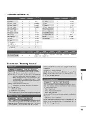
... desired TV ID number in Setup menu. Error Acknowledgement [Command2][ ][Set ID][ ][NG][Data][x] The TV transmits ACK (acknowledgement) based on this model, TV will send the '0', 'a'. [DATA] : Use the small character, if data is controlled. Data1: Illegal Code Data2: Not supported function Data3: Wait more time * In this time, if the data is 0 x ab, it indicates present status data. Aspect Ratio k 05. Remote Control Lock Mode k a 0 ~1 15. Bass...
... desired TV ID number in Setup menu. Error Acknowledgement [Command2][ ][Set ID][ ][NG][Data][x] The TV transmits ACK (acknowledgement) based on this model, TV will send the '0', 'a'. [DATA] : Use the small character, if data is controlled. Data1: Illegal Code Data2: Not supported function Data3: Wait more time * In this time, if the data is 0 x ab, it indicates present status data. Aspect Ratio k 05. Remote Control Lock Mode k a 0 ~1 15. Bass...

