

Service Manual
Page 3
... ...18 8. DIAGNOSIS AND SOLUTION FOR ABNORMAL OPERATION 20 8-2. DISASSEMBLY INSTRUCTIONS 32 10. TROUBLESHOOTING...17 7-1. DRUM & TUB ASSEMBLY 42 10-3. FEATURES & TECHNICAL EXPLANATION 4 3. INSTALLATION & TEST ...8 5. DISPENSER ASSEMBLY 43 2 QC TEST MODE...17 7-3. EXPLODED VIEW ...41 10-1. SPECIFICATIONS ...3 2. BEFORE PERFORMING SERVICE 17 7-2. ERROR DIAGNOSIS AND CHECK LIST 20 8-1. CABINET & CONTROL PANEL ASSEMBLY 41 10-2. PARTS...
... ...18 8. DIAGNOSIS AND SOLUTION FOR ABNORMAL OPERATION 20 8-2. DISASSEMBLY INSTRUCTIONS 32 10. TROUBLESHOOTING...17 7-1. DRUM & TUB ASSEMBLY 42 10-3. FEATURES & TECHNICAL EXPLANATION 4 3. INSTALLATION & TEST ...8 5. DISPENSER ASSEMBLY 43 2 QC TEST MODE...17 7-3. EXPLODED VIEW ...41 10-1. SPECIFICATIONS ...3 2. BEFORE PERFORMING SERVICE 17 7-2. ERROR DIAGNOSIS AND CHECK LIST 20 8-1. CABINET & CONTROL PANEL ASSEMBLY 41 10-2. PARTS...
Service Manual
Page 18
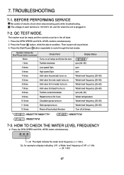
... V AC and DC when the unit is pressed None Check Point Turns on all lamps. 1) : WM2277H*/WM2177H* : WM2077CW : WM2677H*M 7-3. QC TEST MODE. Number of times the Start/Pause button is plugged in the off all lamps and locks the door. 1 time Tumble clockwise. 2 times Low speed ...display indicating 241: a Water level frequency of 241 x.1 kHz = 24.1 kHz 17 Press the Start/Pause button repeatedly to cycle through the test modes. The voltage of electric shock when disconnecting parts while troubleshooting. HOW TO CHECK THE WATER LEVEL FREQUENCY Press the SPIN SPEED and SOIL LEVEL ...
... V AC and DC when the unit is pressed None Check Point Turns on all lamps. 1) : WM2277H*/WM2177H* : WM2077CW : WM2677H*M 7-3. QC TEST MODE. Number of times the Start/Pause button is plugged in the off all lamps and locks the door. 1 time Tumble clockwise. 2 times Low speed ...display indicating 241: a Water level frequency of 241 x.1 kHz = 24.1 kHz 17 Press the Start/Pause button repeatedly to cycle through the test modes. The voltage of electric shock when disconnecting parts while troubleshooting. HOW TO CHECK THE WATER LEVEL FREQUENCY Press the SPIN SPEED and SOIL LEVEL ...
Service Manual
Page 20
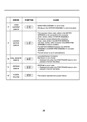
Displayed only when the START/PAUSE button is out of order. Displayed only when the START/PAUSE button is first pressed in the QC Test Mode. • EEPROM is first pressed in the MAIN PWB ASSEMBLY is bad or unstable. • The MOTOR HARNESS between the STATOR ASSEMBLY and MAIN PWB ...) of STATOR ASSEMBLY. • The electric contact between the connectors (3-pin, male, white) in the MOTOR HARNESS and 4-pin, female, white connector in the QC Test Mode. 12 POWER FAILURE • The washer experienced a power failure. 19
Displayed only when the START/PAUSE button is out of order. Displayed only when the START/PAUSE button is first pressed in the QC Test Mode. • EEPROM is first pressed in the MAIN PWB ASSEMBLY is bad or unstable. • The MOTOR HARNESS between the STATOR ASSEMBLY and MAIN PWB ...) of STATOR ASSEMBLY. • The electric contact between the connectors (3-pin, male, white) in the MOTOR HARNESS and 4-pin, female, white connector in the QC Test Mode. 12 POWER FAILURE • The washer experienced a power failure. 19
Service Manual
Page 25
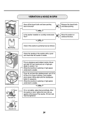
... spinning in high spin (Refer to section 7-2). Is the washer installed on a solidly constructed floor? Once loaded, press power, Rinse+Spin and the start QC test mode and run in high speed, verify that the washer is stable. YES If it is level, tighten the lock nuts up against of the base...
... spinning in high spin (Refer to section 7-2). Is the washer installed on a solidly constructed floor? Once loaded, press power, Rinse+Spin and the start QC test mode and run in high speed, verify that the washer is stable. YES If it is level, tighten the lock nuts up against of the base...
Service Manual
Page 26
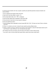
In case of the drum. 2) Start the QC test mode (Refer to section 7-2). 3) Press Delay Wash button, then ' ' is displayed. 4) Press the Spin Speed button repeatedly to select Extra High. 5) Press the Quick Cycle button, ...
In case of the drum. 2) Start the QC test mode (Refer to section 7-2). 3) Press Delay Wash button, then ' ' is displayed. 4) Press the Spin Speed button repeatedly to select Extra High. 5) Press the Quick Cycle button, ...
Service Manual
Page 27
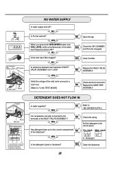
... the inlet valve connector is the water YES level frequency below 246? YES NO Refer to NO WATER SUPPLY Are receptacles correctly connected to 7-2 QC TEST MODE) Check electrical connection. Is the detergent caked or hardened? NO WATER SUPPLY Is water supply shut-off? YES Has detergent been put in the correct...
... the inlet valve connector is the water YES level frequency below 246? YES NO Refer to NO WATER SUPPLY Are receptacles correctly connected to 7-2 QC TEST MODE) Check electrical connection. Is the detergent caked or hardened? NO WATER SUPPLY Is water supply shut-off? YES Has detergent been put in the correct...
Service Manual
Page 32
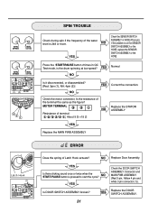
... the ASSEMBLY Connector and MAIN PWB ASSEMBLY START/PAUSE button is the drum spinning at low speed? Press the START/PAUSE button 2 times in QC Test mode, is pressed to start the cycle? (Red 3 pin, Yellow 4 pin and (1) white 3 pin connector (1)). Replace Door Assembly. If the problem is 248 or more...
... the ASSEMBLY Connector and MAIN PWB ASSEMBLY START/PAUSE button is the drum spinning at low speed? Press the START/PAUSE button 2 times in QC Test mode, is pressed to start the cycle? (Red 3 pin, Yellow 4 pin and (1) white 3 pin connector (1)). Replace Door Assembly. If the problem is 248 or more...


