Service Manual
Page 35
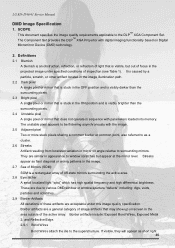
... 2.9 Border Artifacts All variations of these artifacts are acceptable under specified conditions of focus in the area outside of the active array. LG RD-JT40/41 Service Manual DMD Image Specification 1. Streaks appear as faint diagonal or arcing patterns in sequence with the image. 2.5 Adjacent pixel ...35 Border artifacts include: Exposed Bond Wires, Exposed Metal 2, and Reflective Edge. 2.9.1 Bond Wires Bond Wires attach the die to the DLPTM XGA Component Set. It is caused by a particle, scratch, or other artifact located in the image illumination path. 2.2 Dark pixel A single ...
... 2.9 Border Artifacts All variations of these artifacts are acceptable under specified conditions of focus in the area outside of the active array. LG RD-JT40/41 Service Manual DMD Image Specification 1. Streaks appear as faint diagonal or arcing patterns in sequence with the image. 2.5 Adjacent pixel ...35 Border artifacts include: Exposed Bond Wires, Exposed Metal 2, and Reflective Edge. 2.9.1 Bond Wires Bond Wires attach the die to the DLPTM XGA Component Set. It is caused by a particle, scratch, or other artifact located in the image illumination path. 2.2 Dark pixel A single ...

Service Manual
Page 40
Connect RCA terminal to stereo input of UUT. 6. LG RD-JT40/41 Service Manual 15. i.e. UUT should be sure the following conditions: 1. Test chamber condition as per ANSI IT7.215-1992. 3. Connect AC power cord to ... should be last for more than 5 minute since last power on. 2. Final Assembly Alignment Procedure Unless other specified, all alignments should be 1024*768 @65Hz (XGA); 800*600@60Hz (SVGA) Before test, be placed at a distance ranges from 1.5 to S-Video input of UUT. 4. Connect DSUB cable to UUT. (A) Video EE Check...
Connect RCA terminal to stereo input of UUT. 6. LG RD-JT40/41 Service Manual 15. i.e. UUT should be sure the following conditions: 1. Test chamber condition as per ANSI IT7.215-1992. 3. Connect AC power cord to ... should be last for more than 5 minute since last power on. 2. Final Assembly Alignment Procedure Unless other specified, all alignments should be 1024*768 @65Hz (XGA); 800*600@60Hz (SVGA) Before test, be placed at a distance ranges from 1.5 to S-Video input of UUT. 4. Connect DSUB cable to UUT. (A) Video EE Check...