
Service Manual
Page 2
... Secure the Drain Pipe ...8 How to Install...9 Operation ...12 Function of Controls ...12 Disassembly ...13 Mechanical Parts...13 Air handling Parts...14 Electrical Parts ...15 Refrigerating Cycle...17 Schematic Diagram...20 Electronic Control Device...20 Wiring Diagram...21 Components Location ...22 Troubleshooting Guide ...23 Pipeing System ...23 Troubleshooting Guide ...24 Electrical...
... Secure the Drain Pipe ...8 How to Install...9 Operation ...12 Function of Controls ...12 Disassembly ...13 Mechanical Parts...13 Air handling Parts...14 Electrical Parts ...15 Refrigerating Cycle...17 Schematic Diagram...20 Electronic Control Device...20 Wiring Diagram...21 Components Location ...22 Troubleshooting Guide ...23 Pipeing System ...23 Troubleshooting Guide ...24 Electrical...
Service Manual
Page 7
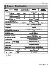
... ITEMS MODELS HBLG8004R(A4/B4) L8004R(Y4)/M8004R(Y4) CL8000ER HBLG1004R L1004R/M1004R POWER SUPPLY 1ø, 115V, 60Hz CAPACITY (BTU/h) 8,000 8,000 10,000 INPUT (W) 820 COOLING RUNNING CURRENT (A) 7.3 740 1,020 7.0 9.4 E.E.R (BTU/W.h) 9.8 10.8 9.8 OPERATING INDOOR ( C) 26.7(DB)* 19.4(WB)** CONDITION OUTDOOR ( C) 35(DB)* 23.9(WB)** REFRIGERANT (R-22) CHARGE 420g(14.8 oz) 410g...
... ITEMS MODELS HBLG8004R(A4/B4) L8004R(Y4)/M8004R(Y4) CL8000ER HBLG1004R L1004R/M1004R POWER SUPPLY 1ø, 115V, 60Hz CAPACITY (BTU/h) 8,000 8,000 10,000 INPUT (W) 820 COOLING RUNNING CURRENT (A) 7.3 740 1,020 7.0 9.4 E.E.R (BTU/W.h) 9.8 10.8 9.8 OPERATING INDOOR ( C) 26.7(DB)* 19.4(WB)** CONDITION OUTDOOR ( C) 35(DB)* 23.9(WB)** REFRIGERANT (R-22) CHARGE 420g(14.8 oz) 410g...
Service Manual
Page 15
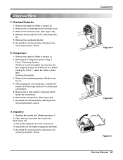
.... (See Figure 19) 4. If there is no valve to section 2) 2. Re-install the components by referring to the removal procedure, above . 8. Overload Protector 1. Discharge the refrigerant system using a FreonTM Recovery System. tor. 5. Re-install the components by referring to section 3) 2. Disconnect all the leads from the overload protec- Leave the valve...
.... (See Figure 19) 4. If there is no valve to section 2) 2. Re-install the components by referring to the removal procedure, above . 8. Overload Protector 1. Discharge the refrigerant system using a FreonTM Recovery System. tor. 5. Re-install the components by referring to section 3) 2. Disconnect all the leads from the overload protec- Leave the valve...
Service Manual
Page 17
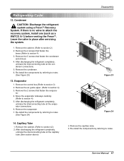
... cabinet. (Refer to section 4) 5. Service Manual 17 If there is no valve to section 3) 2. Capillary Tube 1. After discharging the refrigerant completely, unbraze the interconnecting tube at the evaporator connections. 6. Remove the 4 screws that fasten the condenser and shroud. 4. Remove the condenser...one (such as a WATCO A-1) before venting the FreonTM. Re-install the components by referring to notes. Condenser CAUTION: Discharge the refrigerant system using a FreonTM Recovery System. Remove the cabinet. (Refer to section 4) 3. Remove the air guide upper. (Refer to ...
... cabinet. (Refer to section 4) 5. Service Manual 17 If there is no valve to section 3) 2. Capillary Tube 1. After discharging the refrigerant completely, unbraze the interconnecting tube at the evaporator connections. 6. Remove the 4 screws that fasten the condenser and shroud. 4. Remove the condenser...one (such as a WATCO A-1) before venting the FreonTM. Re-install the components by referring to notes. Condenser CAUTION: Discharge the refrigerant system using a FreonTM Recovery System. Remove the cabinet. (Refer to section 4) 3. Remove the air guide upper. (Refer to ...

Service Manual
Page 18
... is now pulling through the access valve which you installed as the system was opened. 2) Connect the charging cylinder as follows : 1) Refrigeration cycle systems are charged from foaming and being drawn into the pinch-off tool. b. Disassembly NOTICE - Leave the valve in the system.... the hose at the manifold connection. 5) The system is operating correctly, use the pinch-off tube. Do not add the liquid refrigerant to Discharge the refrigerant system using a FreonTM recovery System. d. Replacement of the manifold and entire system. Solder the pinch-off tubes. 3. and c....
... is now pulling through the access valve which you installed as the system was opened. 2) Connect the charging cylinder as follows : 1) Refrigeration cycle systems are charged from foaming and being drawn into the pinch-off tool. b. Disassembly NOTICE - Leave the valve in the system.... the hose at the manifold connection. 5) The system is operating correctly, use the pinch-off tube. Do not add the liquid refrigerant to Discharge the refrigerant system using a FreonTM recovery System. d. Replacement of the manifold and entire system. Solder the pinch-off tubes. 3. and c....

Service Manual
Page 23
...a brief description of the important components and their function in the cooling cycle. ROOM AIR CONITIONER CYCLE OF REFRIGERATION EVAPORATOR COILS COOLED AIR COMPLETE LIQUID BOIL OFF POINT SUCTION LINE COOL LOW PRESSURE VAPOR ROOM AIR HEAT LOAD ...COILS VAPOR INLET HOT DISCHARGED AIR LIQUID PRESSURE DROP MOTOR OUTSIDE COOLING AIR FOR REFRIGERANT PASS THROUGH COMPRESSOR OIL (LIQUID REFRIGERANT) CAPILLARY TUBE Figure 26 LIQUID OUTLET HIGH PRESSURE VAPOR LIQUID REFRIGERANT LOW PRESSURE VAPOR Service Manual 23 Troubleshooting Guide Piping System Troubleshooting Guide CONDENSER ...
...a brief description of the important components and their function in the cooling cycle. ROOM AIR CONITIONER CYCLE OF REFRIGERATION EVAPORATOR COILS COOLED AIR COMPLETE LIQUID BOIL OFF POINT SUCTION LINE COOL LOW PRESSURE VAPOR ROOM AIR HEAT LOAD ...COILS VAPOR INLET HOT DISCHARGED AIR LIQUID PRESSURE DROP MOTOR OUTSIDE COOLING AIR FOR REFRIGERANT PASS THROUGH COMPRESSOR OIL (LIQUID REFRIGERANT) CAPILLARY TUBE Figure 26 LIQUID OUTLET HIGH PRESSURE VAPOR LIQUID REFRIGERANT LOW PRESSURE VAPOR Service Manual 23 Troubleshooting Guide Piping System Troubleshooting Guide CONDENSER ...
Service Manual
Page 24
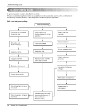
...repair. Adjusting of compressor. Troubleshooting Guide Troubleshooting Guide In general, possible trouble is classified in refrigeration circuit. Check inside gas pressure. Repair clogging in the refrigeration circuit and improper application. Check gas leakage. Clean condenser. Malfunction of compressor. Check heat ... from an electrical defect, and the other is ineffective Air Conditioning caused by a defect in refrigeration circuit. 24 Room Air Conditioner Satisfactory operation with temperature difference of inlet & outlet air ; 44~50°F(7~10°...
...repair. Adjusting of compressor. Troubleshooting Guide Troubleshooting Guide In general, possible trouble is classified in refrigeration circuit. Check inside gas pressure. Repair clogging in the refrigeration circuit and improper application. Check gas leakage. Clean condenser. Malfunction of compressor. Check heat ... from an electrical defect, and the other is ineffective Air Conditioning caused by a defect in refrigeration circuit. 24 Room Air Conditioner Satisfactory operation with temperature difference of inlet & outlet air ; 44~50°F(7~10°...

Service Manual
Page 35
... the thermistor if the circuit is properly sized for the area to be cooled. Remove the cabinet. Test capacitor. Insufficient cooling or heating Capacitor Wiring Refrigerating system Air filter Exhaust damper door Unit undersized Excessive noise Turbo or fan Copper tubing Check the TEMP control. Check the continuity of replace. Replace...
... the thermistor if the circuit is properly sized for the area to be cooled. Remove the cabinet. Test capacitor. Insufficient cooling or heating Capacitor Wiring Refrigerating system Air filter Exhaust damper door Unit undersized Excessive noise Turbo or fan Copper tubing Check the TEMP control. Check the continuity of replace. Replace...
