
Service Manual
Page 2
Air Conditioner Service Manual TABLE OF CONTENTS Safety Precautions...3 Dimensions ...6 Outside Dimensions ...6 Product Specifications ...7 Installation ...8 Select the Best Location ...8 Installation Check ...8 How to Secure the Drain Pipe ...8 How to Install...9 Operation ...12 Function of Controls ...12 Disassembly ...13 Mechanical Parts...13 Air handling Parts...14 Electrical Parts ...15 Refrigerating Cycle...17 Schematic Diagram...20 Electronic Control Device...20 Wiring Diagram...21 Components Location ...22 Troubleshooting Guide ...23 Pipeing System ...23 Troubleshooting Guide ...24 ...
Air Conditioner Service Manual TABLE OF CONTENTS Safety Precautions...3 Dimensions ...6 Outside Dimensions ...6 Product Specifications ...7 Installation ...8 Select the Best Location ...8 Installation Check ...8 How to Secure the Drain Pipe ...8 How to Install...9 Operation ...12 Function of Controls ...12 Disassembly ...13 Mechanical Parts...13 Air handling Parts...14 Electrical Parts ...15 Refrigerating Cycle...17 Schematic Diagram...20 Electronic Control Device...20 Wiring Diagram...21 Components Location ...22 Troubleshooting Guide ...23 Pipeing System ...23 Troubleshooting Guide ...24 ...

Service Manual
Page 5
... after taking the power-plug out from the socket. • It will cause electric shock or failure of the unit when removing the filter. • They are sharp and may cause injury. CAUTION Never touch the metal parts of machine. Leaving it must be repaired or replaced immediately. Safety Precautions If water enters the product, turn off the the power switch of the main...
... after taking the power-plug out from the socket. • It will cause electric shock or failure of the unit when removing the filter. • They are sharp and may cause injury. CAUTION Never touch the metal parts of machine. Leaving it must be repaired or replaced immediately. Safety Precautions If water enters the product, turn off the the power switch of the main...
Service Manual
Page 6
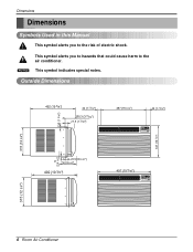
... air conditioner. NOTICE This symbol indicates special notes. Dimensions Dimensions Symbols Used in this Manual This symbol alerts you to hazards that could cause harm to the risk of electric shock. Outside Dimensions 30 (1 3/16") 492 (19 3/8") 42 (1 21/32") 100.3 (3 15/16") 27.5 (1 3/32") 497 (19 9/16") 42 (1 21/32") Cool Energy Saver F1 LOW 'F F2 MED F3 HIGH Fan Dry Timer TEMP MODE TIMER FAN SPEED POWER...
... air conditioner. NOTICE This symbol indicates special notes. Dimensions Dimensions Symbols Used in this Manual This symbol alerts you to hazards that could cause harm to the risk of electric shock. Outside Dimensions 30 (1 3/16") 492 (19 3/8") 42 (1 21/32") 100.3 (3 15/16") 27.5 (1 3/32") 497 (19 9/16") 42 (1 21/32") Cool Energy Saver F1 LOW 'F F2 MED F3 HIGH Fan Dry Timer TEMP MODE TIMER FAN SPEED POWER...
Service Manual
Page 7
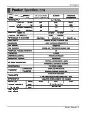
... CHASSIS PROTECTOR COMPRESSOR FAN MOTOR OVERLOAD PROTECTOR INTERNAL THERMAL PROTECTOR POWER CORD 3 WIRE WITH GROUDING ATTACHMENT PLUG (CORD-CONNECTED TYPE) DRAIN SYSTEM DRAIN PIPE OR SPLASHED BY FAN SLINGER NET WEIGHT (lbs/kg) 62/28 62/28 71/32 OUTSIDE DIMENSION (W x H x D) (inch) (mm) 19 9/16 x 12 3/8 x 19 3/8 497 x 315 x 492 * DB : dry bulb ** WB : wet bulb Service Manual 7 Product Specifications Specfications ITEMS MODELS HBLG8004R(A4/B4) L8004R(Y4)/M8004R(Y4) CL8000ER...
... CHASSIS PROTECTOR COMPRESSOR FAN MOTOR OVERLOAD PROTECTOR INTERNAL THERMAL PROTECTOR POWER CORD 3 WIRE WITH GROUDING ATTACHMENT PLUG (CORD-CONNECTED TYPE) DRAIN SYSTEM DRAIN PIPE OR SPLASHED BY FAN SLINGER NET WEIGHT (lbs/kg) 62/28 62/28 71/32 OUTSIDE DIMENSION (W x H x D) (inch) (mm) 19 9/16 x 12 3/8 x 19 3/8 497 x 315 x 492 * DB : dry bulb ** WB : wet bulb Service Manual 7 Product Specifications Specfications ITEMS MODELS HBLG8004R(A4/B4) L8004R(Y4)/M8004R(Y4) CL8000ER...

Service Manual
Page 8
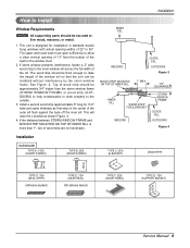
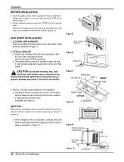
... slightly so the back is installed securely. 4 Avoid placing furniture or draperies in the power cord. ABOUT / 1 4 " Over 20" Figure 1 Installation Check The setting conditions must extend outward for Electric Heater Model) 3. Install the unit where the sun does not shine directly on the outdside of the Base Pan. (Figure. 2) 8 Room Air Conditioner Drain Pipe Drain Cap Figure 2 Restriction of outside of the air conditioner. ciency of the cabinet must...
... slightly so the back is installed securely. 4 Avoid placing furniture or draperies in the power cord. ABOUT / 1 4 " Over 20" Figure 1 Installation Check The setting conditions must extend outward for Electric Heater Model) 3. Install the unit where the sun does not shine directly on the outdside of the Base Pan. (Figure. 2) 8 Room Air Conditioner Drain Pipe Drain Cap Figure 2 Restriction of outside of the air conditioner. ciency of the cabinet must...
Service Manual
Page 9
... 1" MAX. 3/4" CLEARANCE INNER SILL WOOD STRIP FOR L BRACKET INDOORS STORM WINDOW FRAME OUTER SILL OUTDOORS Figure 4 Installation HARDWARE TYPE A: 11EA (SHORT SCREW) TYPE B: 5EA (WOOD SCREW) TYPE C: 3EA (L BACKET) DRAIN PIPE 10mm 16mm TYPE D: 1EA (SEAL STRIP) (Adhesive backed) TYPE E: 1EA (SASH SEAL) (Not adhesive backed) TYPE F: 2EA (GUIDE PANEL) TYPE G: 1EA (SUPPORT BACKET) Service Manual 9 See Figure. 4. Installation How to Install Window Requirements NOTICE All supporting parts should be approximately 3/4" higher than 1", two of...
... 1" MAX. 3/4" CLEARANCE INNER SILL WOOD STRIP FOR L BRACKET INDOORS STORM WINDOW FRAME OUTER SILL OUTDOORS Figure 4 Installation HARDWARE TYPE A: 11EA (SHORT SCREW) TYPE B: 5EA (WOOD SCREW) TYPE C: 3EA (L BACKET) DRAIN PIPE 10mm 16mm TYPE D: 1EA (SEAL STRIP) (Adhesive backed) TYPE E: 1EA (SASH SEAL) (Not adhesive backed) TYPE F: 2EA (GUIDE PANEL) TYPE G: 1EA (SUPPORT BACKET) Service Manual 9 See Figure. 4. Installation How to Install Window Requirements NOTICE All supporting parts should be approximately 3/4" higher than 1", two of...
Service Manual
Page 10
... the open window. Insert the guide panels into the notches of the bottom window. (Figure. 6) NOW START INSTALLATION 1. CAUTION: During the following step, hold unit securely in Figure. 10. 8" SHORT SIDE 8" OUTSIDE Figure 8 L BRACKET C ool E nergy S aver F F1 LOW F2 ME D F3 HIGH Fan Dry T imer TE MP Figure 9 WINDOW FRAME UPPER GUIDE C enter Line SEAL BOTTOM GUIDE ABOUT 1/4" 10 Room Air Conditioner Figure 10 L BRACKET Type A Figure 5 SEAL STRIP (TYPE D) Type...
... the open window. Insert the guide panels into the notches of the bottom window. (Figure. 6) NOW START INSTALLATION 1. CAUTION: During the following step, hold unit securely in Figure. 10. 8" SHORT SIDE 8" OUTSIDE Figure 8 L BRACKET C ool E nergy S aver F F1 LOW F2 ME D F3 HIGH Fan Dry T imer TE MP Figure 9 WINDOW FRAME UPPER GUIDE C enter Line SEAL BOTTOM GUIDE ABOUT 1/4" 10 Room Air Conditioner Figure 10 L BRACKET Type A Figure 5 SEAL STRIP (TYPE D) Type...

Service Manual
Page 11
... seal between the windows. Fasten the L bracket using 4 screws (TYPE B) to electrical outlet. 4. Window installation of the guide panels, and save for attaching power cord to secure them, as shown in Figure. 11. Close the guide panels. L Bracket Type A Type B Figure 11 Installation Sash Seal (Type F) Service Manual 11 INSTALL THE SASH SEAL AND SASH LOCK a. Lift the air conditioner from the window ad remove the sash seal from getting into the room, as shown in...
... seal between the windows. Fasten the L bracket using 4 screws (TYPE B) to electrical outlet. 4. Window installation of the guide panels, and save for attaching power cord to secure them, as shown in Figure. 11. Close the guide panels. L Bracket Type A Type B Figure 11 Installation Sash Seal (Type F) Service Manual 11 INSTALL THE SASH SEAL AND SASH LOCK a. Lift the air conditioner from the window ad remove the sash seal from getting into the room, as shown in...
Service Manual
Page 12
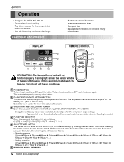
... temperature of the room. FAN SPEED SELECTOR Every time you push this button, it is selected, the fan stops when the compressor stops cooling.a Approximately every 3 minutes the fan will turn off state, this button, it will be set the time when the unit will turn on or turn on and check the room air to 30°C by pressing the timer button. DISPLAY Cool Energy Saver F1 LOW F2 MED F3 HIGH 'F 6 Fan Dry Timer TEMP 2 MODE TIMER FAN SPEED POWER 3 5 4 1 REMOTE CONTROL Power 1 Temp 2 Fan...
... temperature of the room. FAN SPEED SELECTOR Every time you push this button, it is selected, the fan stops when the compressor stops cooling.a Approximately every 3 minutes the fan will turn off state, this button, it will be set the time when the unit will turn on or turn on and check the room air to 30°C by pressing the timer button. DISPLAY Cool Energy Saver F1 LOW F2 MED F3 HIGH 'F 6 Fan Dry Timer TEMP 2 MODE TIMER FAN SPEED POWER 3 5 4 1 REMOTE CONTROL Power 1 Temp 2 Fan...

Service Manual
Page 16
Open the top cover from the control box. (See Figure 22) 4. Disconnect the front panel from the control box. (Refer to section 9) 3. Motor 1. Remove the cabinet. (Refer to section 5) 4. Disconnect two leads from the air guide. (See Figure 23) 5. Remove the fan. (Refer to section 2) 2. Power Cord 1. Remove the motor. 6. Re-install the component by referring to the above removal procedure, above .(See Figure 23) 16 Room Air Conditioner Figure 22...
Open the top cover from the control box. (See Figure 22) 4. Disconnect the front panel from the control box. (Refer to section 9) 3. Motor 1. Remove the cabinet. (Refer to section 5) 4. Disconnect two leads from the air guide. (See Figure 23) 5. Remove the fan. (Refer to section 2) 2. Power Cord 1. Remove the motor. 6. Re-install the component by referring to the above removal procedure, above .(See Figure 23) 16 Room Air Conditioner Figure 22...

Service Manual
Page 18
... which you installed as the system was opened. 2) Connect the charging cylinder as illustrated figure 25A. 2) Start the vacuum pump, slowly open manifold valves A and B with two full turns counterclockwise and leave the valves open . 4. A rise in pressure would indicate a possible leak or moisture remaining in place after servicing the system. 2. With valves A and B closed, stop the vacuum pump. 4) Remove the hose from...
... which you installed as the system was opened. 2) Connect the charging cylinder as illustrated figure 25A. 2) Start the vacuum pump, slowly open manifold valves A and B with two full turns counterclockwise and leave the valves open . 4. A rise in pressure would indicate a possible leak or moisture remaining in place after servicing the system. 2. With valves A and B closed, stop the vacuum pump. 4) Remove the hose from...

Service Manual
Page 20
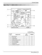
Schematic Diagram Schematic Diagram Electronic Control Device 20 Room Air Conditioner CN-TELE SMW200-03 (RD) 33 22 11 5V C01T 0.1 50V PIPE-TH CN-TH2 SMW250-02 11 22 C02T 0.001 D01T 1N4148 Q04T A104M Q01T C104M 5V Q03T C104M 5V Q02T A104M R01T 1K Rx C03T 0.001 25V Tx J7 11 2 12 1 ROOM... Model Auto Restart Non Auto Restart EEPROM CAT93C46 1 A0 Vcc 8 2 A1 WP 7 3 A2 SCL 6 4 GND SDA 5 EEPROM R04P O X X O R04P 5V R02P R03P 20K 20K Option2 Option1 Pipe TH Room TH VAref VSS Osc out Osc in /Reset TEST HVB SW2 SW1 S/V4WAY FAN MOTOR CAPACITOR FAN C HERM MAIN POWER COMP...
Schematic Diagram Schematic Diagram Electronic Control Device 20 Room Air Conditioner CN-TELE SMW200-03 (RD) 33 22 11 5V C01T 0.1 50V PIPE-TH CN-TH2 SMW250-02 11 22 C02T 0.001 D01T 1N4148 Q04T A104M Q01T C104M 5V Q03T C104M 5V Q02T A104M R01T 1K Rx C03T 0.001 25V Tx J7 11 2 12 1 ROOM... Model Auto Restart Non Auto Restart EEPROM CAT93C46 1 A0 Vcc 8 2 A1 WP 7 3 A2 SCL 6 4 GND SDA 5 EEPROM R04P O X X O R04P 5V R02P R03P 20K 20K Option2 Option1 Pipe TH Room TH VAref VSS Osc out Osc in /Reset TEST HVB SW2 SW1 S/V4WAY FAN MOTOR CAPACITOR FAN C HERM MAIN POWER COMP...
Service Manual
Page 21
... 8 4 OLP WIRING DIAGRAM AIR FILTER ASSEMBLY LOCATION NO. DESCRIPTION 1 MOTOR ASSY 2 CAPACITOR 3 COMPRESSOR 4 OVERLOAD PROTECTOR 5 DC PCB ASSEMBLY 6 AC PCB ASSEMBLY 7 THERMISTOR 8 PLASMA FILTER ASSY S: Service Parts N: Non Service Parts Q'TY PER SET REMARKS 1 S 1 S 1 S 1 S 1 S 1 S 1 S 1 S Service Manual 21 ASSEMBLY BK RD 3 COMP. Wiring Diagram Schematic Diagram 1 BK CN-MOTOR CN-AC/DC CN-AC/DC GN/YL BL 5 (GN) MOTOR RD YL DC PCB OR ASSEMBLY RY-LOW RY-MED RY-HI CAPACITOR CN-TH1 YL 2 F POWER...
... 8 4 OLP WIRING DIAGRAM AIR FILTER ASSEMBLY LOCATION NO. DESCRIPTION 1 MOTOR ASSY 2 CAPACITOR 3 COMPRESSOR 4 OVERLOAD PROTECTOR 5 DC PCB ASSEMBLY 6 AC PCB ASSEMBLY 7 THERMISTOR 8 PLASMA FILTER ASSY S: Service Parts N: Non Service Parts Q'TY PER SET REMARKS 1 S 1 S 1 S 1 S 1 S 1 S 1 S 1 S Service Manual 21 ASSEMBLY BK RD 3 COMP. Wiring Diagram Schematic Diagram 1 BK CN-MOTOR CN-AC/DC CN-AC/DC GN/YL BL 5 (GN) MOTOR RD YL DC PCB OR ASSEMBLY RY-LOW RY-MED RY-HI CAPACITOR CN-TH1 YL 2 F POWER...
Service Manual
Page 24
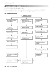
... Cooling Check cold air circulation for smooth flow. Check inside gas pressure. Malfunction of air filter. Troubleshooting Guide Troubleshooting Guide In general, possible trouble is classified in the refrigeration circuit and improper application. Unit runs but poor cooling. Dirty indoor coil (Heat exchanger) Malfunction of fan Clogged of compressor. Check heat load increase. Obstruction at air outlet Correct above trouble Check outdoor coil (heat exchanger) & the fan operation. Check clogging in refrigeration circuit. 24 Room Air Conditioner Satisfactory...
... Cooling Check cold air circulation for smooth flow. Check inside gas pressure. Malfunction of air filter. Troubleshooting Guide Troubleshooting Guide In general, possible trouble is classified in the refrigeration circuit and improper application. Unit runs but poor cooling. Dirty indoor coil (Heat exchanger) Malfunction of fan Clogged of compressor. Check heat load increase. Obstruction at air outlet Correct above trouble Check outdoor coil (heat exchanger) & the fan operation. Check clogging in refrigeration circuit. 24 Room Air Conditioner Satisfactory...

Service Manual
Page 25
...power source. Irregular motor insulation ( ). Irregular motor resistance ( ) Irregular motor insulation ( ) Replacement of compressor (Motor damaged) Regular but fails to start . Improper wiring. Improper wiring. Fails to Start Troubleshooting Guide Check of fan motor capacitor. Gas leakage of feeler bulb of thermostat Check of rotor, metal). Fan only fails to start. Replacement of compressor (locking of control switch. Replacement Improper thermostat setting. Check circuit breaker and fuse. Service Manual 25 Capacitor check. Replacement of compressor capacitor. Compressor...
...power source. Irregular motor insulation ( ). Irregular motor resistance ( ) Irregular motor insulation ( ) Replacement of compressor (Motor damaged) Regular but fails to start . Improper wiring. Improper wiring. Fails to Start Troubleshooting Guide Check of fan motor capacitor. Gas leakage of feeler bulb of thermostat Check of rotor, metal). Fan only fails to start. Replacement of compressor (locking of control switch. Replacement Improper thermostat setting. Check circuit breaker and fuse. Service Manual 25 Capacitor check. Replacement of compressor capacitor. Compressor...

Service Manual
Page 27
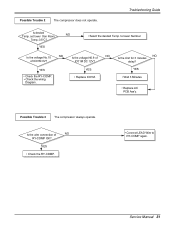
... RY-COMP OK? YES • Replace IC01M. YES • Wait 3 Minutes. • Replace MAIN PCB Ass'y. Service Manual 27 Troubleshooting Guide Is setting Temp. set lower than Room NO Temp.-0.5°C? Possible Trouble 3 The compressor always operate. YES • Select the setting Temp. NO Does the Unit delay for 3 minutes? Is the wire connection of NO IC01M DC 12V? Possible Trouble 2 The compressor does not operate. to RY-COMP again. Is...
... RY-COMP OK? YES • Replace IC01M. YES • Wait 3 Minutes. • Replace MAIN PCB Ass'y. Service Manual 27 Troubleshooting Guide Is setting Temp. set lower than Room NO Temp.-0.5°C? Possible Trouble 3 The compressor always operate. YES • Select the setting Temp. NO Does the Unit delay for 3 minutes? Is the wire connection of NO IC01M DC 12V? Possible Trouble 2 The compressor does not operate. to RY-COMP again. Is...

Service Manual
Page 28
... CN-AC/DC of Energy Saver does not operate. Is the voltage NO.1 or 2 or 4 NO of AC & DC PCB. 28 Room Air Conditioner YES • Reference to OWNER'S MANUAL. • Set the mode key to Energy Saver mode. • Check the Energy Saver mode key. • Check the pattern of IC01M DC 12V? Is the mode NO key pushed once more from cool mode? YES Is the voltage...
... CN-AC/DC of Energy Saver does not operate. Is the voltage NO.1 or 2 or 4 NO of AC & DC PCB. 28 Room Air Conditioner YES • Reference to OWNER'S MANUAL. • Set the mode key to Energy Saver mode. • Check the Energy Saver mode key. • Check the pattern of IC01M DC 12V? Is the mode NO key pushed once more from cool mode? YES Is the voltage...
Service Manual
Page 31
.... • Connect LEAD Wire to lower Number. to RY-COMP again. Possible Trouble 3 The compressor always operate. Possible Trouble 2 The compressor does not operate. YES • Select the desired Temp. NO NO Is the Unit for 3 minutes delay? YES • Check the RY-COMP. • Check the wiring Diagram. YES • Replace IC01M. Troubleshooting Guide Is desired Temp. Service Manual 31 set lower than Room NO Temp.-0.5°C? Is the voltage...
.... • Connect LEAD Wire to lower Number. to RY-COMP again. Possible Trouble 3 The compressor always operate. Possible Trouble 2 The compressor does not operate. YES • Select the desired Temp. NO NO Is the Unit for 3 minutes delay? YES • Check the RY-COMP. • Check the wiring Diagram. YES • Replace IC01M. Troubleshooting Guide Is desired Temp. Service Manual 31 set lower than Room NO Temp.-0.5°C? Is the voltage...

Service Manual
Page 32
... RY-Hi or RY-Med or RY-Lo. • Check the wiring diagram. YES • Replace Receiver Ass'y. • Replace IC01M. • Replace IC01M. • Replace the battery. ••CChheecckk tthheePPCCBBpaptatettrenr.n. • Connect connector to CN-AC/DC exactly. 32 Room Air Conditioner Possible Trouble 5 Remote controller does not operate. YES Is the voltage NO.16 or 15 or 13 NO of...
... RY-Hi or RY-Med or RY-Lo. • Check the wiring diagram. YES • Replace Receiver Ass'y. • Replace IC01M. • Replace IC01M. • Replace the battery. ••CChheecckk tthheePPCCBBpaptatettrenr.n. • Connect connector to CN-AC/DC exactly. 32 Room Air Conditioner Possible Trouble 5 Remote controller does not operate. YES Is the voltage NO.16 or 15 or 13 NO of...

Service Manual
Page 35
... manufacturers rating. Straighten the fins or replace the coil. Thermistor Capacitor (Discharge capacitor before reassembling. Check the compressor overload, if externally mounted. Clean the interior base before servicing.) Compressor Overload Compressor cycles on the coil surface, head pressures will not run, but fan motor runs. Close if open . Insufficient cooling or heating Capacitor Wiring Refrigerating system Air filter Exhaust damper door Unit undersized Excessive noise Turbo or fan Copper tubing Check the TEMP control. If not at the lowest number, set...
... manufacturers rating. Straighten the fins or replace the coil. Thermistor Capacitor (Discharge capacitor before reassembling. Check the compressor overload, if externally mounted. Clean the interior base before servicing.) Compressor Overload Compressor cycles on the coil surface, head pressures will not run, but fan motor runs. Close if open . Insufficient cooling or heating Capacitor Wiring Refrigerating system Air filter Exhaust damper door Unit undersized Excessive noise Turbo or fan Copper tubing Check the TEMP control. If not at the lowest number, set...


