Owner's Manual
Page 1
LED LCD MONITOR TV MODELS M2080D M2380DF M2280D M2780DF M2380D M2780D www.lg.com ENGLISH OWNER'S MANUAL LED LCD MONITOR TV Please read this manual carefully before operating your set and retain it for future reference.
LED LCD MONITOR TV MODELS M2080D M2380DF M2280D M2780DF M2380D M2780D www.lg.com ENGLISH OWNER'S MANUAL LED LCD MONITOR TV Please read this manual carefully before operating your set and retain it for future reference.

Owner's Manual
Page 4
Note: You can adjust the power indicator in the OPTION menu. 4 The image shown may be somewhat different from your Monitor set is a simplified representation of the front panel. M2080D / M2280D M2380D / M2780D M2380DF / M2780DF PREPARATION 1 1 2 3 45 6 7 89 1 IR RECEIVER (remote control signal receiver) 2 SPEAKER (WOOFER) 3 INPUT BUTTON 4 MENU BUTTON 5 ENTER BUTTON 6 VOLUME BUTTON 7 CHANNEL BUTTON 8 POWER BUTTON 9 POWER INDICATOR Illuminates blue when the set . PREPARATION FRONT PANEL INFORMATION ■■ This is switched on.
Note: You can adjust the power indicator in the OPTION menu. 4 The image shown may be somewhat different from your Monitor set is a simplified representation of the front panel. M2080D / M2280D M2380D / M2780D M2380DF / M2780DF PREPARATION 1 1 2 3 45 6 7 89 1 IR RECEIVER (remote control signal receiver) 2 SPEAKER (WOOFER) 3 INPUT BUTTON 4 MENU BUTTON 5 ENTER BUTTON 6 VOLUME BUTTON 7 CHANNEL BUTTON 8 POWER BUTTON 9 POWER INDICATOR Illuminates blue when the set . PREPARATION FRONT PANEL INFORMATION ■■ This is switched on.

Owner's Manual
Page 5
... a PC. 5 HEADPHONE SOCKET Plug headphones into the headphone socket. 6 RS-232C IN (CONTROL & SERVICE) PORT Connect to the RS-232C port on a PC. M2080D / M2280D M2380D / M2780D M2380DF / M2780DF 1 2 3 45 6 78 9 10 11 1 DC ADAPTER PORT Connect to the power jack. 2 HDMI INPUT Connect an HDMI signal to... HDMI IN or a DVI (VIDEO) signal to HDMI IN with an optical audio cable. 4 RGB/DVI AUDIO INPUT Connect the audio from your Monitor set. PREPARATION BACK PANEL INFORMATION ■■ This is used for Service or Hotel mode. 7 RGB INPUT (PC) Connect the output from a PC. ...
... a PC. 5 HEADPHONE SOCKET Plug headphones into the headphone socket. 6 RS-232C IN (CONTROL & SERVICE) PORT Connect to the RS-232C port on a PC. M2080D / M2280D M2380D / M2780D M2380DF / M2780DF 1 2 3 45 6 78 9 10 11 1 DC ADAPTER PORT Connect to the power jack. 2 HDMI INPUT Connect an HDMI signal to... HDMI IN or a DVI (VIDEO) signal to HDMI IN with an optical audio cable. 4 RGB/DVI AUDIO INPUT Connect the audio from your Monitor set. PREPARATION BACK PANEL INFORMATION ■■ This is used for Service or Hotel mode. 7 RGB INPUT (PC) Connect the output from a PC. ...

Owner's Manual
Page 6
Coin 6 Stand Base 3 Use a Coin on a cushioned surface that will protect the Monitor set and its screen from your Monitor set. 1 Carefully place the product screen side down on the bottom of the stand base and turn the screw clockwise to tighten. PREPARATION PREPARATION STAND INSTALLATION M2080D/M2280D/M2380D/M2780D ■■ The image shown may be somewhat different from damage. 2 Insert the Stand Base into the product.
Coin 6 Stand Base 3 Use a Coin on a cushioned surface that will protect the Monitor set and its screen from your Monitor set. 1 Carefully place the product screen side down on the bottom of the stand base and turn the screw clockwise to tighten. PREPARATION PREPARATION STAND INSTALLATION M2080D/M2280D/M2380D/M2780D ■■ The image shown may be somewhat different from damage. 2 Insert the Stand Base into the product.

Owner's Manual
Page 7
PREPARATION STAND INSTALLATION ■■ The image shown may be somewhat different from your Monitor set and its screen from damage. 2 Insert the Stand Base into the product. M2380DF/M2780DF 1 Carefully place the product screen side down on the bottom of the stand base and turn the screw clockwise to tighten. Coin 7 Stand Base 3 Use a Coin on a cushioned surface that will protect the Monitor set .
PREPARATION STAND INSTALLATION ■■ The image shown may be somewhat different from your Monitor set and its screen from damage. 2 Insert the Stand Base into the product. M2380DF/M2780DF 1 Carefully place the product screen side down on the bottom of the stand base and turn the screw clockwise to tighten. Coin 7 Stand Base 3 Use a Coin on a cushioned surface that will protect the Monitor set .

Owner's Manual
Page 8
PREPARATION PREPARATION M2080D/M2280D/M2380D/M2780D DETACHING THE STAND ■■ The image shown may be somewhat different from your Monitor set. 1 Place the Monitor set screen side down on a cushion or soft cloth. 2 Detach the Stand Base from the set by turning the screw to the left with a Coin. Coin 3 Pull the stand base. Stand Base 8
PREPARATION PREPARATION M2080D/M2280D/M2380D/M2780D DETACHING THE STAND ■■ The image shown may be somewhat different from your Monitor set. 1 Place the Monitor set screen side down on a cushion or soft cloth. 2 Detach the Stand Base from the set by turning the screw to the left with a Coin. Coin 3 Pull the stand base. Stand Base 8

Owner's Manual
Page 9
PREPARATION DETACHING THE STAND ■■ The image shown may be somewhat different from the set . Coin 3 Pull the stand base. Stand Base 9 M2380DF/M2780DF 1 Place the Monitor set screen side down on a cushion or soft cloth. 2 Detach the Stand Base from your Monitor set by turning the screw to the left with a Coin.
PREPARATION DETACHING THE STAND ■■ The image shown may be somewhat different from the set . Coin 3 Pull the stand base. Stand Base 9 M2380DF/M2780DF 1 Place the Monitor set screen side down on a cushion or soft cloth. 2 Detach the Stand Base from your Monitor set by turning the screw to the left with a Coin.

Owner's Manual
Page 10
Assemble the screw 2 points. Remove the screw 2 points. 2. Pull the stand body. 3. Screw 10 PREPARATION PREPARATION DETACHING THE STAND BODY (Only M2080D/ M2280D/M2380D/M2780D) ■ When using a VESA mount on the monitor set, you may wish to remove the stand body. ■ The image shown may be somewhat different from your Monitor set. 1.
Assemble the screw 2 points. Remove the screw 2 points. 2. Pull the stand body. 3. Screw 10 PREPARATION PREPARATION DETACHING THE STAND BODY (Only M2080D/ M2280D/M2380D/M2780D) ■ When using a VESA mount on the monitor set, you may wish to remove the stand body. ■ The image shown may be somewhat different from your Monitor set. 1.

Owner's Manual
Page 11
... (optional), attach it carefully so it coming away from failure to the screw mounting interface dimensions and mounting screw specifications. 5. LG is not responsible for any damage resulting from the wall. See the optional Tilt Wall Mounting Bracket Installation and Setup Guide. 10... Be sure to the back of 10 cm on each side and from your Monitor set to a wall, attach the wall mounting interface (optional) to use a VESA standard wall mount pad and screws. < Screw Mounting Interface Dimensions > r M2080D / M2280D / M2380D / M2380DF : 75 mm x 75 mm hole spacing r M2780D /...
... (optional), attach it carefully so it coming away from failure to the screw mounting interface dimensions and mounting screw specifications. 5. LG is not responsible for any damage resulting from the wall. See the optional Tilt Wall Mounting Bracket Installation and Setup Guide. 10... Be sure to the back of 10 cm on each side and from your Monitor set to a wall, attach the wall mounting interface (optional) to use a VESA standard wall mount pad and screws. < Screw Mounting Interface Dimensions > r M2080D / M2280D / M2380D / M2380DF : 75 mm x 75 mm hole spacing r M2780D /...

Owner's Manual
Page 12
... somewhat different from your viewing position. M2780D M2780DF PREPARATION DESKTOP PEDESTAL INSTALLATION ■■ The image shown may be somewhat different from the wall. M2080D / M2280D M2380D / M2780D 10 cm 10 cm 10 cm 10 cm M2380DF / M2780DF 12 10 cm 10 cm 10 cm 10 cm After installing the set..., you can adjust the set manually to the left or right direction by 179 degrees to suit your Monitor set . For proper ventilation, allow a clearance of 10 cm on each side and from your...
... somewhat different from your viewing position. M2780D M2780DF PREPARATION DESKTOP PEDESTAL INSTALLATION ■■ The image shown may be somewhat different from the wall. M2080D / M2280D M2380D / M2780D 10 cm 10 cm 10 cm 10 cm M2380DF / M2780DF 12 10 cm 10 cm 10 cm 10 cm After installing the set..., you can adjust the set manually to the left or right direction by 179 degrees to suit your Monitor set . For proper ventilation, allow a clearance of 10 cm on each side and from your...

Owner's Manual
Page 13
... put your set . Adjust the position of the panel in various ways for maximum comfort. * Tilt Range -5° 10° -5° 10° PREPARATION M2080D / M2280D / M2380D / M2780D M2380DF / M2780DF LOCATION Position your finger(s) in a position to any unnecessary vibration, moisture, dust or heat. WARNING ■ When adjusting the angle of...
... put your set . Adjust the position of the panel in various ways for maximum comfort. * Tilt Range -5° 10° -5° 10° PREPARATION M2080D / M2280D / M2380D / M2780D M2380DF / M2780DF LOCATION Position your finger(s) in a position to any unnecessary vibration, moisture, dust or heat. WARNING ■ When adjusting the angle of...

Owner's Manual
Page 14
... on the screen, appearing as tiny red, green, or blue spots. This is normal, there is an optional accessory. The product is turned on the monitor's performance. If the product feels cold to the user's guide provided with the Kensington Security System. - For detailed installation and use of time. Some minute..., they have no adverse effect on . PREPARATION PREPARATION KENSINGTON SECURITY SYSTEM - Connect the Kensington Security System cable as notebook PCs and LCD projectors. NOTES a. b. c. M2080D / M2280D M2380D / M2780D M2380DF / M2780DF 14
... on the screen, appearing as tiny red, green, or blue spots. This is normal, there is an optional accessory. The product is turned on the monitor's performance. If the product feels cold to the user's guide provided with the Kensington Security System. - For detailed installation and use of time. Some minute..., they have no adverse effect on . PREPARATION PREPARATION KENSINGTON SECURITY SYSTEM - Connect the Kensington Security System cable as notebook PCs and LCD projectors. NOTES a. b. c. M2080D / M2280D M2380D / M2780D M2380DF / M2780DF 14

Owner's Manual
Page 15
... set . ANTENNA CONNECTION ■■ For optimum picture quality, adjust the antenna's direction. ■■ An antenna cable and converter are not included with the Monitor set to be split for outdoor antenna) Antenna UHF VHF Signal Amplifier ■■ To get better picture quality in poor signal areas, install a signal...
... set . ANTENNA CONNECTION ■■ For optimum picture quality, adjust the antenna's direction. ■■ An antenna cable and converter are not included with the Monitor set to be split for outdoor antenna) Antenna UHF VHF Signal Amplifier ■■ To get better picture quality in poor signal areas, install a signal...
Owner's Manual
Page 16
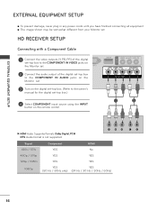
.... 2 Connect the audio output of the digital set-top box to the COMPONENT IN AUDIO jacks on the Monitor set. 3 Turn on the remote control. 1 2 ►►HDMI Audio Supported formats: Dolby Digital, PCM DTS Audio format is not supported. EXTERNAL EQUIPMENT SETUP EXTERNAL ... damage, never plug in any power cords until you have finished connecting all equipment. ■■ The image shown may be somewhat different from your Monitor set -top box.) 4 Select COMPONENT input source using the INPUT button on the digital set-top box. (Refer to the owner's manual for the digital...
.... 2 Connect the audio output of the digital set-top box to the COMPONENT IN AUDIO jacks on the Monitor set. 3 Turn on the remote control. 1 2 ►►HDMI Audio Supported formats: Dolby Digital, PCM DTS Audio format is not supported. EXTERNAL EQUIPMENT SETUP EXTERNAL ... damage, never plug in any power cords until you have finished connecting all equipment. ■■ The image shown may be somewhat different from your Monitor set -top box.) 4 Select COMPONENT input source using the INPUT button on the digital set-top box. (Refer to the owner's manual for the digital...
Owner's Manual
Page 17
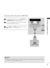
NOTE ►►Check that your HDMI cable is a high speed HDMI cable. If the HDMI cables are not high speed, flickering or no screen display can result. 17 EXTERNAL EQUIPMENT SETUP Connecting a Set-top Box with an HDMI Cable 1 Connect the digital set-top box to the HDMI/DVI IN 1 or HDMI/DVI IN 2 jack on the Monitor set. 2 Turn on the digital set-top box. (Refer to the owner's manual for the digital set-top box.) 3 Select HDMI 1 or HDMI 2 input source using the INPUT button on the remote control. 1 !
NOTE ►►Check that your HDMI cable is a high speed HDMI cable. If the HDMI cables are not high speed, flickering or no screen display can result. 17 EXTERNAL EQUIPMENT SETUP Connecting a Set-top Box with an HDMI Cable 1 Connect the digital set-top box to the HDMI/DVI IN 1 or HDMI/DVI IN 2 jack on the Monitor set. 2 Turn on the digital set-top box. (Refer to the owner's manual for the digital set-top box.) 3 Select HDMI 1 or HDMI 2 input source using the INPUT button on the remote control. 1 !
Owner's Manual
Page 18
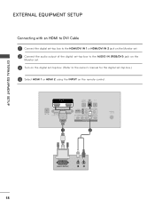
EXTERNAL EQUIPMENT SETUP EXTERNAL EQUIPMENT SETUP Connecting with an HDMI to DVI Cable 1 Connect the digital set-top box to the HDMI/DVI IN 1 or HDMI/DVI IN 2 jack on the Monitor set. 2 Connect the audio output of the digital set-top box to the AUDIO IN (RGB/DVI) jack on the Monitor set. 3 Turn on the digital set-top box. (Refer to the owner's manual for the digital set-top box.) 4 Select HDMI 1 or HDMI 2 using the INPUT on the remote control. 1 2 18
EXTERNAL EQUIPMENT SETUP EXTERNAL EQUIPMENT SETUP Connecting with an HDMI to DVI Cable 1 Connect the digital set-top box to the HDMI/DVI IN 1 or HDMI/DVI IN 2 jack on the Monitor set. 2 Connect the audio output of the digital set-top box to the AUDIO IN (RGB/DVI) jack on the Monitor set. 3 Turn on the digital set-top box. (Refer to the owner's manual for the digital set-top box.) 4 Select HDMI 1 or HDMI 2 using the INPUT on the remote control. 1 2 18

Owner's Manual
Page 19
... the DVD player's manual for operating instructions. 1 2 Component Input Ports For better picture quality, connect a DVD player to the COMPONENT IN AUDIO jacks on the Monitor set Y PB PR Video output Ports on the Monitor set. 2 Connect the audio outputs of the DVD to the component input ports as shown below.
... the DVD player's manual for operating instructions. 1 2 Component Input Ports For better picture quality, connect a DVD player to the COMPONENT IN AUDIO jacks on the Monitor set Y PB PR Video output Ports on the Monitor set. 2 Connect the audio outputs of the DVD to the component input ports as shown below.

Owner's Manual
Page 20
If the HDMI cables are not high speed, flickering or no screen display can result. 20 EXTERNAL EQUIPMENT SETUP EXTERNAL EQUIPMENT SETUP Connecting with an HDMI Cable 1 Connect the HDMI output of the DVD to the HDMI/ DVI IN 1 or HDMI/DVI IN 2 jack on the Monitor set. 2 Select HDMI 1 or HDMI 2 using the INPUT on the remote control. 3 Refer to the DVD player's manual for operating instructions. 1 ! NOTE ►►Check that your HDMI cable is a high speed HDMI cable.
If the HDMI cables are not high speed, flickering or no screen display can result. 20 EXTERNAL EQUIPMENT SETUP EXTERNAL EQUIPMENT SETUP Connecting with an HDMI Cable 1 Connect the HDMI output of the DVD to the HDMI/ DVI IN 1 or HDMI/DVI IN 2 jack on the Monitor set. 2 Select HDMI 1 or HDMI 2 using the INPUT on the remote control. 3 Refer to the DVD player's manual for operating instructions. 1 ! NOTE ►►Check that your HDMI cable is a high speed HDMI cable.

Owner's Manual
Page 21
EXTERNAL EQUIPMENT SETUP VCR SETUP ■■ To avoid picture noise (interference), allow adequate distance between the set . Connecting with an RF Cable 1 Wall Jack 2 Antenna 1 Connect the ANT OUT socket of the VCR to the ANTENNA/CABLE IN socket on the Monitor set. 2 Connect the antenna cable to the ANT IN socket of the VCR. 3 Press PLAY on the VCR and match the appropriate channel between the VCR and set and the VCR for viewing. 21
EXTERNAL EQUIPMENT SETUP VCR SETUP ■■ To avoid picture noise (interference), allow adequate distance between the set . Connecting with an RF Cable 1 Wall Jack 2 Antenna 1 Connect the ANT OUT socket of the VCR to the ANTENNA/CABLE IN socket on the Monitor set. 2 Connect the antenna cable to the ANT IN socket of the VCR. 3 Press PLAY on the VCR and match the appropriate channel between the VCR and set and the VCR for viewing. 21

Owner's Manual
Page 23
If you want to enjoy digital broadcasting through 5.1-channel speakers, connect the OPTICAL DIGITAL AUDIO OUT terminal on the back of the monitor SET to a home theater (or amp). 1 Connect one end of an optical cable to the OPTICAL DIGITAL AUDIO OUT port. 2 Connect the other end of .... 3 Set the "TV Speaker option - Looking at the laser beam may damage your vision. 23 EXTERNAL EQUIPMENT SETUP DIGITAL AUDIO OUT SETUP To send the monitor SET's audio signal to external audio equipment, use the Digital Audio Output (Optical) port.
If you want to enjoy digital broadcasting through 5.1-channel speakers, connect the OPTICAL DIGITAL AUDIO OUT terminal on the back of the monitor SET to a home theater (or amp). 1 Connect one end of an optical cable to the OPTICAL DIGITAL AUDIO OUT port. 2 Connect the other end of .... 3 Set the "TV Speaker option - Looking at the laser beam may damage your vision. 23 EXTERNAL EQUIPMENT SETUP DIGITAL AUDIO OUT SETUP To send the monitor SET's audio signal to external audio equipment, use the Digital Audio Output (Optical) port.


