Owner's Manual
Page 2
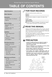
... Electrical Safety 9 Temporary Use of an Adapter 11 Temporary Use of an Extension Cord 11 Installation 12 Window Requirements 12 Size 12 Clearance 13 Preparation of Chassis 14 Unit Installation 15 Operating Instructions 17 Location and Function of Controls 17 Remote Control Operations ........18 Remote Controller...do not play with the air conditioner. • If the power cord requires replacement, have an Authorized Servicer install an exact replacement part. • Installation work must be performed in the event you need to common problems in the chart of this page in ...
... Electrical Safety 9 Temporary Use of an Adapter 11 Temporary Use of an Extension Cord 11 Installation 12 Window Requirements 12 Size 12 Clearance 13 Preparation of Chassis 14 Unit Installation 15 Operating Instructions 17 Location and Function of Controls 17 Remote Control Operations ........18 Remote Controller...do not play with the air conditioner. • If the power cord requires replacement, have an Authorized Servicer install an exact replacement part. • Installation work must be performed in the event you need to common problems in the chart of this page in ...
Owner's Manual
Page 3
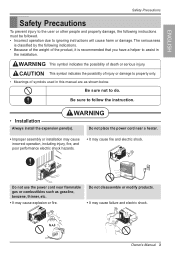
.... CAUTION This symbol indicates the possibility of injury or damage to property only. • Meanings of symbols used in the installation. ENGLISH Safety Precautions Safety Precautions To prevent injury to the user or other people and property damage, the following indications. ... thinner, etc. • It may cause explosion or fire. WARNING • Installation Always install the expansion panel(s). Do not use the power cord near a heater. • Improper assembly or installation may cause incorrect operation, including injury, fire, and poor performance electric shock hazards. ...
.... CAUTION This symbol indicates the possibility of injury or damage to property only. • Meanings of symbols used in the installation. ENGLISH Safety Precautions Safety Precautions To prevent injury to the user or other people and property damage, the following indications. ... thinner, etc. • It may cause explosion or fire. WARNING • Installation Always install the expansion panel(s). Do not use the power cord near a heater. • Improper assembly or installation may cause incorrect operation, including injury, fire, and poor performance electric shock hazards. ...
Owner's Manual
Page 4
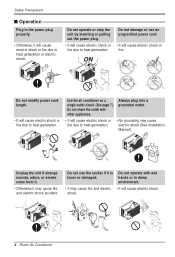
... the power plug. • It will cause electric shock or fire. Do not damage or use the socket if it may cause electric shock (See Installation Manual). ON Do not modify power cord length. • It will cause electric shock or fire due to heat generation or electric shock. Safety Precautions...
... the power plug. • It will cause electric shock or fire. Do not damage or use the socket if it may cause electric shock (See Installation Manual). ON Do not modify power cord length. • It will cause electric shock or fire due to heat generation or electric shock. Safety Precautions...
Owner's Manual
Page 5
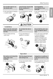
CAUTION Do not block the inlet or outlet. • It may cause injury. entire house. ENGLISH • Installation Never touch the metal parts of the unit when removing the filter. • They are sharp and may cause failure of the window, creating a safety ...; It may cause injury. • It may cause explosion, fire, or electric shock. Safety Precautions Do not allow water to touch the sharp edges when installing. Ensure that the outer case is not damaged by the head when taking it damaged could result in the air conditioner falling out of appliance...
CAUTION Do not block the inlet or outlet. • It may cause injury. entire house. ENGLISH • Installation Never touch the metal parts of the unit when removing the filter. • They are sharp and may cause failure of the window, creating a safety ...; It may cause injury. • It may cause explosion, fire, or electric shock. Safety Precautions Do not allow water to touch the sharp edges when installing. Ensure that the outer case is not damaged by the head when taking it damaged could result in the air conditioner falling out of appliance...
Owner's Manual
Page 7
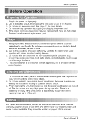
... to direct airflow for extended periods of the unit when removing the filter. The air conditioner is damaged and requires replacement, have an Authorized Servicer install an exact replacement part. See page 11 for Operation 1. Such usage could damage the items. 4. Usage 1. Use a dedicated circuit. When cleaning the unit, first make...
... to direct airflow for extended periods of the unit when removing the filter. The air conditioner is damaged and requires replacement, have an Authorized Servicer install an exact replacement part. See page 11 for Operation 1. Such usage could damage the items. 4. Usage 1. Use a dedicated circuit. When cleaning the unit, first make...
Owner's Manual
Page 12
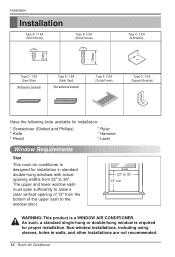
...(Sash Seal) (Not adhesive backed) Type F: 2 EA (Guide Panel) Type G: 1 EA (Support Bracket) Have the following tools available for installation: * Screwdriver (Slotted and Phillips) * Knife * Pencil * Ruler * Hammer * Level Window Requirements Size This room air conditioner is designed for proper... window stool. 22" to 36" 13" min WARNING: This product is required for installation in walls, and other installations are not recommended. 12 Room Air Conditioner Non-window installations, including using sleeves, holes in standard double-hung windows with actual opening widths from 22...
...(Sash Seal) (Not adhesive backed) Type F: 2 EA (Guide Panel) Type G: 1 EA (Support Bracket) Have the following tools available for installation: * Screwdriver (Slotted and Phillips) * Knife * Pencil * Ruler * Hammer * Level Window Requirements Size This room air conditioner is designed for proper... window stool. 22" to 36" 13" min WARNING: This product is required for installation in walls, and other installations are not recommended. 12 Room Air Conditioner Non-window installations, including using sleeves, holes in standard double-hung windows with actual opening widths from 22...

Owner's Manual
Page 13
... interference by 11/2" wide and same thickness as shown Figure. A Figure. B Owner's Manual 13 See Figure. Install a second wood strip (approximately 6" long by the storm window frame. 2. If the distance between Storm Window Frame and Wood Strip Mounted on Top of wood ... interference, fasten a 2" wide wood strip to the inner window sill across the full width of the sill flush against the back off the inner sill. Installation Clearance Proper clearance enhances the cooling efficiency of the unit and prevents heat radiation of the window sill so that the unit can be thick...
... interference by 11/2" wide and same thickness as shown Figure. A Figure. B Owner's Manual 13 See Figure. Install a second wood strip (approximately 6" long by the storm window frame. 2. If the distance between Storm Window Frame and Wood Strip Mounted on Top of wood ... interference, fasten a 2" wide wood strip to the inner window sill across the full width of the sill flush against the back off the inner sill. Installation Clearance Proper clearance enhances the cooling efficiency of the unit and prevents heat radiation of the window sill so that the unit can be thick...
Owner's Manual
Page 14
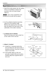
... the inner sill. Tip! : Use a long screwdriver and installing the screws will be easier. Cut the adhesive-backed seal strip (Type D) to hold unit securely in window Open the window and mark center line .... Remove the backing from the seal strip and attach the seal strip to place bracket edge flush against back of bracket as shown. Attach L bracket 4-1. Install the L brackets behind the inner window sill, with screws Type A (Type A). Be sure to the underside of the air conditioner. Seal Strip (Type D) 3. Use the...
... the inner sill. Tip! : Use a long screwdriver and installing the screws will be easier. Cut the adhesive-backed seal strip (Type D) to hold unit securely in window Open the window and mark center line .... Remove the backing from the seal strip and attach the seal strip to place bracket edge flush against back of bracket as shown. Attach L bracket 4-1. Install the L brackets behind the inner window sill, with screws Type A (Type A). Be sure to the underside of the air conditioner. Seal Strip (Type D) 3. Use the...
Owner's Manual
Page 15
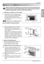
... behind side panel frames. Stuff the sash seal between the glass and the window to prevent air and insects from window. 1. Unit Installation Installation Caution: During the following step, hold unit firmly until window sash is lowered to top channel behind the upper guide of the air conditioner.... Carefully lift the air conditioner and slide it does not, there is a problem with the installation. 2. Personal injury or property damage may result if unit falls from getting into the open window. Tip! : When the air conditioner drops...
... behind side panel frames. Stuff the sash seal between the glass and the window to prevent air and insects from window. 1. Unit Installation Installation Caution: During the following step, hold unit firmly until window sash is lowered to top channel behind the upper guide of the air conditioner.... Carefully lift the air conditioner and slide it does not, there is a problem with the installation. 2. Personal injury or property damage may result if unit falls from getting into the open window. Tip! : When the air conditioner drops...
Owner's Manual
Page 16
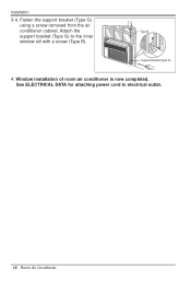
Support Bracket (Type G) 4. Fasten the support bracket (Type G) using a screw removed from the air conditioner cabinet. Window installation of room air conditioner is now completed. Installation 3-4. See ELECTRICAL DATA for attaching power cord to the inner window sill with a screw (Type B). Attach the Type B support bracket (Type G) to electrical outlet. 16 Room Air Conditioner
Support Bracket (Type G) 4. Fasten the support bracket (Type G) using a screw removed from the air conditioner cabinet. Window installation of room air conditioner is now completed. Installation 3-4. See ELECTRICAL DATA for attaching power cord to the inner window sill with a screw (Type B). Attach the Type B support bracket (Type G) to electrical outlet. 16 Room Air Conditioner
Owner's Manual
Page 20
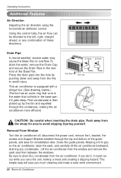
... you don't, it gets deep. Removal From Window Turn the air conditioner off, disconnect the power cord, remove the L bracket, the screws and Support Bracket installed through the condenser, making a mess and creating a slipping hazard. Keeping a firm grip on the air conditioner, raise the sash, and carefully tilt the air conditioner...
... you don't, it gets deep. Removal From Window Turn the air conditioner off, disconnect the power cord, remove the L bracket, the screws and Support Bracket installed through the condenser, making a mess and creating a slipping hazard. Keeping a firm grip on the air conditioner, raise the sash, and carefully tilt the air conditioner...
Service Manual
Page 2
... 4.2 PIPING SYSTEM ...16 4.3 TROUBLESHOOTING GUIDE ...17 5. EXPLODED VIEW ...23 7. PREFACE ...3 1.1 FEATURES...3 1.2 SPECIFICATIONS ...3 1.3 LOCATIONS OF CONTROLS ...4 1.4 SAFETY PRECAUTIONS ...4 1.5 INSULATION RESISTANCE TEST ...4 2. CONTENTS 1. INSTALLATION ...12 3.1 SELECT THE BEST LOCATION ...12 3.2 HOW TO INSTALL ...12 3.3 ELECTRICAL DATA ...15 4. DISASSEMBLY INSTRUCTIONS 5 2.1 MECHANICAL PARTS ...5 2.1.1 FRONT GRILLE ...5 2.1.2 CABINET...5 2.1.3 CONTROL BOARD ...5 2.2 AIR HANDLING PARTS ...6 2.2.1 AIR GUIDE UPPER ...6 2.2.2 ORIFICE, TURBO...
... 4.2 PIPING SYSTEM ...16 4.3 TROUBLESHOOTING GUIDE ...17 5. EXPLODED VIEW ...23 7. PREFACE ...3 1.1 FEATURES...3 1.2 SPECIFICATIONS ...3 1.3 LOCATIONS OF CONTROLS ...4 1.4 SAFETY PRECAUTIONS ...4 1.5 INSULATION RESISTANCE TEST ...4 2. CONTENTS 1. INSTALLATION ...12 3.1 SELECT THE BEST LOCATION ...12 3.2 HOW TO INSTALL ...12 3.3 ELECTRICAL DATA ...15 4. DISASSEMBLY INSTRUCTIONS 5 2.1 MECHANICAL PARTS ...5 2.1.1 FRONT GRILLE ...5 2.1.2 CABINET...5 2.1.3 CONTROL BOARD ...5 2.2 AIR HANDLING PARTS ...6 2.2.1 AIR GUIDE UPPER ...6 2.2.2 ORIFICE, TURBO...
Service Manual
Page 3
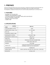
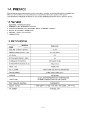
... safety precautions prior to servicing the unit. 1.1 FEATURES • DESIGNED FOR COOLING ONLY • POWERFUL AND INCREDIBLE COOLING • TOP-DOWN CHASSIS FOR THE SIMPLE INSTALLATION AND SERVICE • BUILT-IN ADJUSTABLE THERMOSTAT • WASHABLE ONE-TOUCH FILTER • COMPACT SIZE 1.2 SPECIFICATIONS ITEMS MODELS COOLING CAPACITY (BTU/h) POWER SUPPLY (Phase, V, Hz...
... safety precautions prior to servicing the unit. 1.1 FEATURES • DESIGNED FOR COOLING ONLY • POWERFUL AND INCREDIBLE COOLING • TOP-DOWN CHASSIS FOR THE SIMPLE INSTALLATION AND SERVICE • BUILT-IN ADJUSTABLE THERMOSTAT • WASHABLE ONE-TOUCH FILTER • COMPACT SIZE 1.2 SPECIFICATIONS ITEMS MODELS COOLING CAPACITY (BTU/h) POWER SUPPLY (Phase, V, Hz...
Service Manual
Page 4
... safety precautions prior to servicing the unit. 1.1 FEATURES • DESIGNED FOR COOLING ONLY • POWERFUL AND INCREDIBLE COOLING • TOP-DOWN CHASSIS FOR THE SIMPLE INSTALLATION AND SERVICE • BUILT-IN ADJUSTABLE THERMOSTAT • WASHABLE ONE-TOUCH FILTER • COMPACT SIZE 1.2 SPECIFICATIONS ITEMS MODELS COOLING CAPACITY (BTU/h) POWER SUPPLY (Phase, V, Hz...
... safety precautions prior to servicing the unit. 1.1 FEATURES • DESIGNED FOR COOLING ONLY • POWERFUL AND INCREDIBLE COOLING • TOP-DOWN CHASSIS FOR THE SIMPLE INSTALLATION AND SERVICE • BUILT-IN ADJUSTABLE THERMOSTAT • WASHABLE ONE-TOUCH FILTER • COMPACT SIZE 1.2 SPECIFICATIONS ITEMS MODELS COOLING CAPACITY (BTU/h) POWER SUPPLY (Phase, V, Hz...

Service Manual
Page 6
... (Refer to procedures above . 2.1.3 CONTROL BOARD 1. Pull the top of the front grille away from source of their slots. (See Figure 2) 4. Re-install by pulling them off. Pull the control board toward yourself. Discharge the capacitor before servicing. 2. Replace the grille by referring to wiring diagram on page...that secure the cabinet to Section 2.1.1) 3. NOTE : Controls, wires, and capacitor are now accessible for the fan motor and compressor. (See Figure 5) 7. Re-install components by placing the tabs in this manual or inside control board.) Figure 3 Figure 4 Figure 5 -5-
... (Refer to procedures above . 2.1.3 CONTROL BOARD 1. Pull the top of the front grille away from source of their slots. (See Figure 2) 4. Re-install by pulling them off. Pull the control board toward yourself. Discharge the capacitor before servicing. 2. Replace the grille by referring to wiring diagram on page...that secure the cabinet to Section 2.1.1) 3. NOTE : Controls, wires, and capacitor are now accessible for the fan motor and compressor. (See Figure 5) 7. Re-install components by placing the tabs in this manual or inside control board.) Figure 3 Figure 4 Figure 5 -5-
Service Manual
Page 7
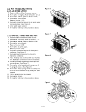
... of fan and turbo fan by referring to Section 2.1.1) 3. Pull the fan and turbo fan outward. 13. Disconnect the unit from the condenser. 9. Re-install by hand plier. (See Figure 9) 12. Remove the cabinet. (Refer to the procedures above . Press the snap area of the air guide blower. (...See Figure 8) 11. Re-install by pushing the snap area of shroud with the evaporator and condenser. (See Figure 7) 10. Lift the compressor upward with your thumbs. Remove the shroud...
... of fan and turbo fan by referring to Section 2.1.1) 3. Pull the fan and turbo fan outward. 13. Disconnect the unit from the condenser. 9. Re-install by hand plier. (See Figure 9) 12. Remove the cabinet. (Refer to the procedures above . Press the snap area of the air guide blower. (...See Figure 8) 11. Re-install by pushing the snap area of shroud with the evaporator and condenser. (See Figure 7) 10. Lift the compressor upward with your thumbs. Remove the shroud...
Service Manual
Page 8
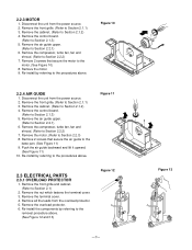
Remove the front grille. (Refer to Section 2.2.1) 6. Remove the air guide upper. (Refer to Section 2.1.1) 3. Re-install by referring to the procedures above . (See Figure 12 and 13) Figure 12 -7- Remove the control board. (Refer to...Figure 13 Figure 10 2.2.4 AIR GUIDE 1. Remove the motor. (Refer to the procedures above. Re-install the components by referring to Section 2.2.3) 8. Disconnect the unit from the overload protector. 5. 2.2.3 MOTOR 1. Re-install by referring to the motor. (See Figure 10) 8. Remove the terminal cover. 4. Remove the compressor...
Remove the front grille. (Refer to Section 2.2.1) 6. Remove the air guide upper. (Refer to Section 2.1.1) 3. Re-install by referring to the procedures above . (See Figure 12 and 13) Figure 12 -7- Remove the control board. (Refer to...Figure 13 Figure 10 2.2.4 AIR GUIDE 1. Remove the motor. (Refer to the procedures above. Re-install the components by referring to Section 2.2.3) 8. Disconnect the unit from the overload protector. 5. 2.2.3 MOTOR 1. Re-install by referring to the motor. (See Figure 10) 8. Remove the terminal cover. 4. Remove the compressor...
Service Manual
Page 9
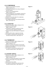
...and discharge pipes at the compressor connections. 5. Remove all the leads of the thermostat terminals. 5. Remove the thermostat. 6. Re-install the components by referring to Section 2.1.2) 2. Remove the front grille and cabinet. (Refer to the removal procedure above . (See...the cabinet. (Refer to the removal procedure above . (See Figure 17) Figure 17 -8- Remove 2 screws which fasten the rotary switch. 4. Re-install the components by referring to Section 2.1) 2. Remove the rotary switch. 6. Remove 2 screws which fasten the thermostat. 4. Remove the control board. (...
...and discharge pipes at the compressor connections. 5. Remove all the leads of the thermostat terminals. 5. Remove the thermostat. 6. Re-install the components by referring to Section 2.1.2) 2. Remove the front grille and cabinet. (Refer to the removal procedure above . (See...the cabinet. (Refer to the removal procedure above . (See Figure 17) Figure 17 -8- Remove 2 screws which fasten the rotary switch. 4. Re-install the components by referring to Section 2.1) 2. Remove the rotary switch. 6. Remove 2 screws which fasten the thermostat. 4. Remove the control board. (...
Service Manual
Page 10
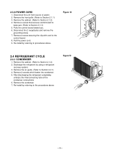
... completely, unbraze the interconnecting tube at the condenser connections. 6. Figure 18 2.4 REFRIGERANT CYCLE 2.4.1 CONDENSER 1. Remove 2 screws which fasten the condenser. 5. Re-install by using a refrigerant recovery system. 3. Remove a screw that secures control board to base pan. (Refer to Section 2.1.1) 3. Remove the cabinet. (Refer ... 4. Disconnect the 2 receptacles and remove the grounding screw. 7. Remove the air guide. (Refer to procedures above . Re-install by referring to Section 2.2.1) 4. Figure19 -9- Remove the cabinet. (Refer to the procedures above .
... completely, unbraze the interconnecting tube at the condenser connections. 6. Figure 18 2.4 REFRIGERANT CYCLE 2.4.1 CONDENSER 1. Remove 2 screws which fasten the condenser. 5. Re-install by using a refrigerant recovery system. 3. Remove a screw that secures control board to base pan. (Refer to Section 2.1.1) 3. Remove the cabinet. (Refer ... 4. Disconnect the 2 receptacles and remove the grounding screw. 7. Remove the air guide. (Refer to procedures above . Re-install by referring to Section 2.2.1) 4. Figure19 -9- Remove the cabinet. (Refer to the procedures above .

Service Manual
Page 11
... vacuum gauge for any subsequent procedures. 6. Discharge the line at the manifold connection. 7-3. If more charge is opened. 7-2. Re-install by means of the charge. When replacing the refrigerating cycle, be closed and left in figure 21A. 6-2. The vacuum pump is ...completing the above . 2.4.3 CAPILLARY TUBE 1. Open valve C. Use sil-fos solder and solder the pinch-off tube. 2.4.2 EVAPORATOR 1. Re-install by using a refrigerant recovery system. 3. wise. After discharging the refrigerant completely, unbraze the interconnecting tube at the condenser connections. 5. Turn...
... vacuum gauge for any subsequent procedures. 6. Discharge the line at the manifold connection. 7-3. If more charge is opened. 7-2. Re-install by means of the charge. When replacing the refrigerating cycle, be closed and left in figure 21A. 6-2. The vacuum pump is ...completing the above . 2.4.3 CAPILLARY TUBE 1. Open valve C. Use sil-fos solder and solder the pinch-off tube. 2.4.2 EVAPORATOR 1. Re-install by using a refrigerant recovery system. 3. wise. After discharging the refrigerant completely, unbraze the interconnecting tube at the condenser connections. 5. Turn...


