
Service Manual
Page 2
... ...4 Safety Precautions...5 Dimensions...11 Indoor Unit...11 Outdoor Unit ...12 Product Specifications ...13 Installation ...15 Installation Parts...15 Installation Tools...15 Select the best location ...16 Piping length and elevation ...17 Fixing Installation Plate(Standart Type 18 Preparing work for Installation (Artcool Type Only 19 Flaring Work and Connection of Piping 21 Flaring work...21...
... ...4 Safety Precautions...5 Dimensions...11 Indoor Unit...11 Outdoor Unit ...12 Product Specifications ...13 Installation ...15 Installation Parts...15 Installation Tools...15 Select the best location ...16 Piping length and elevation ...17 Fixing Installation Plate(Standart Type 18 Preparing work for Installation (Artcool Type Only 19 Flaring Work and Connection of Piping 21 Flaring work...21...

Service Manual
Page 5
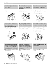
... Safety Precautions To prevent injury to the user or other people and property damage, the following indications. Be sure to do. Install the panel and the cover Always install a dedicated cir- WARNING I Installation Do not use a defective or under- er or fuse. • There is risk of fire or electric shock. • Improper...
... Safety Precautions To prevent injury to the user or other people and property damage, the following indications. Be sure to do. Install the panel and the cover Always install a dedicated cir- WARNING I Installation Do not use a defective or under- er or fuse. • There is risk of fire or electric shock. • Improper...
Service Manual
Page 6
... open. Do not place anything on the power cable. • There is risk of fire, electric shock, explosion, or injury. Be cautious when unpacking and installing the product. • Sharp edges could fall with age. • It may cause injury, accident, or damage to ensure that power cable could not be... risk of fire or electric shock. Take care to the product. • If the base collapses, the air conditioner could cause injury. shock. Do not install the product on the condenser and evaporator. Be especially careful of fire, electric shock, explosion, or injury. Do not...
... open. Do not place anything on the power cable. • There is risk of fire, electric shock, explosion, or injury. Be cautious when unpacking and installing the product. • Sharp edges could fall with age. • It may cause injury, accident, or damage to ensure that power cable could not be... risk of fire or electric shock. Take care to the product. • If the base collapses, the air conditioner could cause injury. shock. Do not install the product on the condenser and evaporator. Be especially careful of fire, electric shock, explosion, or injury. Do not...
Service Manual
Page 8
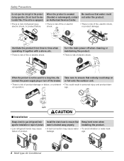
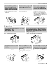
... water • To avoid vibration or water leak- or fall onto the outdoor unit. • There is risk of electric shock. CAUTION I Installation Always check for a long time, dis- water is not be used for gas (refrigerant) leak- failure of fire, electric shock, or product damage.... When the product is drained away properly. age. Take care to ensure that Keep level even when age after installation or repair of product damage or failure, or unintend- • This could during operation. (Do not touch the elec- (flooded or ...
... water • To avoid vibration or water leak- or fall onto the outdoor unit. • There is risk of electric shock. CAUTION I Installation Always check for a long time, dis- water is not be used for gas (refrigerant) leak- failure of fire, electric shock, or product damage.... When the product is drained away properly. age. Take care to ensure that Keep level even when age after installation or repair of product damage or failure, or unintend- • This could during operation. (Do not touch the elec- (flooded or ...
Service Manual
Page 9
...a consumer air conditioner, not a precision refrigeration system. • There is risk of air flow. Do not use harsh detergents, solvents, etc. Safety Precautions Do not install the product where the noise or hot air from the outdoor unit could cause product malfunction or inefficient operation. Do not... install the product where it will be exposed to sea wind (salt spray) directly. • Avoid personal injury. • It may cause corrosion on the ...
...a consumer air conditioner, not a precision refrigeration system. • There is risk of air flow. Do not use harsh detergents, solvents, etc. Safety Precautions Do not install the product where the noise or hot air from the outdoor unit could cause product malfunction or inefficient operation. Do not... install the product where it will be exposed to sea wind (salt spray) directly. • Avoid personal injury. • It may cause corrosion on the ...
Service Manual
Page 11
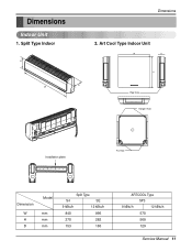
Dimensions Indoor Unit 1. Art Cool Type Indoor Unit W D H Pipe Hole Hanger Hole Installation plate Fix Hole Dimension W H D Model mm mm mm Split Type S4 SE 9 kBtu/h 12 kBtu/h 840 895 270 282 153 165 ARTCOOL Type SP3 9 kBtu/h 12 kBtu/h 570 568 129 Service Manual 11 Split Type Indoor H D W Dimensions 2.
Dimensions Indoor Unit 1. Art Cool Type Indoor Unit W D H Pipe Hole Hanger Hole Installation plate Fix Hole Dimension W H D Model mm mm mm Split Type S4 SE 9 kBtu/h 12 kBtu/h 840 895 270 282 153 165 ARTCOOL Type SP3 9 kBtu/h 12 kBtu/h 570 568 129 Service Manual 11 Split Type Indoor H D W Dimensions 2.
Service Manual
Page 14
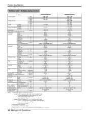
...176;F)WB -Interconnecting Piping Length 7.5m -Level Difference of innovation some specifications may be changed without notification. 14 Multi type Air Conditioner A2UH243FA0(LMU240HE) 9,000~24,000 2637~7033 2267~6037 9,000~24,000 2637~7033 2267~6037 1170~2390 1220~2440 7.7~10.1 7.4~9.8 1,208/230...*800*320) 69(152) 30 15 7.5 7.5 40.2*34.3*17.3 (1020*870*440) SE 12K +SE 12K 54/114 Number of Zero. Installation Indoor Unit~Outdoor Unit m Height Difference Indoor Unit~Indoor Unit m Packing Dimension W*H*D inch(mm) Testing Combinations Stuffing Quantity 20/40ft A2UC243FA0(LMU240CE) 9,...
...176;F)WB -Interconnecting Piping Length 7.5m -Level Difference of innovation some specifications may be changed without notification. 14 Multi type Air Conditioner A2UH243FA0(LMU240HE) 9,000~24,000 2637~7033 2267~6037 9,000~24,000 2637~7033 2267~6037 1170~2390 1220~2440 7.7~10.1 7.4~9.8 1,208/230...*800*320) 69(152) 30 15 7.5 7.5 40.2*34.3*17.3 (1020*870*440) SE 12K +SE 12K 54/114 Number of Zero. Installation Indoor Unit~Outdoor Unit m Height Difference Indoor Unit~Indoor Unit m Packing Dimension W*H*D inch(mm) Testing Combinations Stuffing Quantity 20/40ft A2UC243FA0(LMU240CE) 9,...
Service Manual
Page 15
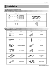
Installation Parts Installation plate Type "B" screw Installation Type "A" screw and plastic anchor Remote Control Holder Installation Tools Figure Name Screw driver Electric Drill Measuring Tape, Knife Hole Core Drill Spanner Torque wrench Figure Name Ohmmeter Hexagonal wrench Ammeter Gas Leak Detector Thermometer, Level Flaring Tool Set Service Manual 15 Installation Read carefully, and then follow step by step.
Installation Parts Installation plate Type "B" screw Installation Type "A" screw and plastic anchor Remote Control Holder Installation Tools Figure Name Screw driver Electric Drill Measuring Tape, Knife Hole Core Drill Spanner Torque wrench Figure Name Ohmmeter Hexagonal wrench Ammeter Gas Leak Detector Thermometer, Level Flaring Tool Set Service Manual 15 Installation Read carefully, and then follow step by step.
Service Manual
Page 16
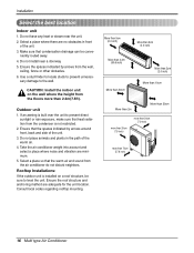
...and anchoring method are minimum. 5. Ensure the spaces indicated by arrows around front, back and side of the unit. 3. Outdoor unit 1. Rooftop Installations: If the outdoor unit is not restricted. 2. Do not have any heat or steam near a doorway. 5. Make sure that the spaces ...indicated by arrows from the floors more than 2.3m(7.5ft). niently routed away. 4. CAUTION: Install the indoor unit on a roof structure, be conve- Consult local codes regarding rooftop mounting. More than 5cm (2.0 inch) More than 5cm (2.0 inch) ...
...and anchoring method are minimum. 5. Ensure the spaces indicated by arrows around front, back and side of the unit. 3. Outdoor unit 1. Rooftop Installations: If the outdoor unit is not restricted. 2. Do not have any heat or steam near a doorway. 5. Make sure that the spaces ...indicated by arrows from the floors more than 2.3m(7.5ft). niently routed away. 4. CAUTION: Install the indoor unit on a roof structure, be conve- Consult local codes regarding rooftop mounting. More than 5cm (2.0 inch) More than 5cm (2.0 inch) ...
Service Manual
Page 17
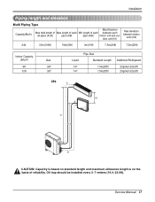
... Type Capacity(Btu/h) Max Elevation Max total length of Max length of each all pipes (A+B) pipe (A/B) pipe (A/B) indoor unit and out- Oil trap should be installed every 5~7 meters (16.4~23.0ft). Service Manual 17 door unit (h1) Max elevation between indoor units (h2) 24k 30m(100ft) 15m(50ft) 3m(10ft) 7.5m...
... Type Capacity(Btu/h) Max Elevation Max total length of Max length of each all pipes (A+B) pipe (A/B) pipe (A/B) indoor unit and out- Oil trap should be installed every 5~7 meters (16.4~23.0ft). Service Manual 17 door unit (h1) Max elevation between indoor units (h2) 24k 30m(100ft) 15m(50ft) 3m(10ft) 7.5m...
Service Manual
Page 18
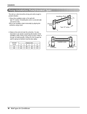
... Type "A" screw 2. CHASSIS Distance (mm) (Grade) A B C D S4 50 105 59 105 SE 65 110 85 110 D Installation plate B C Ø70mm Left rear piping A Ø70mm Right rear piping 18 Multi type Air Conditioner Measure the wall and mark the ...centerline. It is also important to use anchor bolts. • Mount the installation plate horizontally by aligning the centerline using a level. Mount the installation plate on a concrete wall, use caution concerning the location of the installation plate-routing of the wiring to prevent vibration 1. If mounting the unit on ...
... Type "A" screw 2. CHASSIS Distance (mm) (Grade) A B C D S4 50 105 59 105 SE 65 110 85 110 D Installation plate B C Ø70mm Left rear piping A Ø70mm Right rear piping 18 Multi type Air Conditioner Measure the wall and mark the ...centerline. It is also important to use anchor bolts. • Mount the installation plate horizontally by aligning the centerline using a level. Mount the installation plate on a concrete wall, use caution concerning the location of the installation plate-routing of the wiring to prevent vibration 1. If mounting the unit on ...
Service Manual
Page 19
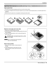
CAUTION: After removing the pipe hole, cut the burr for Installation (Artcool Type Only) Open panel front 1. Pipe hole Adhesive Only one desiring direction Connecting part Drain hose rubber cap Service Manual 19 Pull up to ... panel a bit, and separate connecting wire with product. Remove the rubber stopple of desired direction of drain pan, and join drain hose and connecting hose. Installation Preparing work for safety. The moment of lifting the both lower parts of cover side. Remove two screws(for fixing cover pipe) 2. In case of...
CAUTION: After removing the pipe hole, cut the burr for Installation (Artcool Type Only) Open panel front 1. Pipe hole Adhesive Only one desiring direction Connecting part Drain hose rubber cap Service Manual 19 Pull up to ... panel a bit, and separate connecting wire with product. Remove the rubber stopple of desired direction of drain pan, and join drain hose and connecting hose. Installation Preparing work for safety. The moment of lifting the both lower parts of cover side. Remove two screws(for fixing cover pipe) 2. In case of...
Service Manual
Page 20
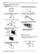
...to No. 5 on this time, Remove the map) (Falling attention) INSTALLATION GUIDE MAP Hanger hole (Rear side of nothing wrong in the matter, connect the pipe and the wire. (Installation manual reference) I Sticking the installation guide map and fixing Indoor unit 1. Drill the piercing part for hanging... product with a ø50mm hole core drill. First, Drive the two points of 30-35mm when piercing a screw point. Put an Installation Guide Map on the horizontal setting line, and Fix lightly the map by horizontal meter on the desired surface. Plastic anchors Plastic anchors 4....
...to No. 5 on this time, Remove the map) (Falling attention) INSTALLATION GUIDE MAP Hanger hole (Rear side of nothing wrong in the matter, connect the pipe and the wire. (Installation manual reference) I Sticking the installation guide map and fixing Indoor unit 1. Drill the piercing part for hanging... product with a ø50mm hole core drill. First, Drive the two points of 30-35mm when piercing a screw point. Put an Installation Guide Map on the horizontal setting line, and Fix lightly the map by horizontal meter on the desired surface. Plastic anchors Plastic anchors 4....
Service Manual
Page 22
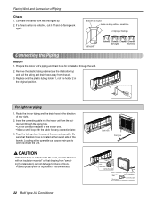
... "sweating"(condensation) will not damage furniture or floors. *Foamed polyethylene or equivalent is defective, cut it off and do flaring work with the cable for installation through the piping hole. • Do not connect the cable to overflow inside the room, insulate the hose with an insulation material* so that the...
... "sweating"(condensation) will not damage furniture or floors. *Foamed polyethylene or equivalent is defective, cut it off and do flaring work with the cable for installation through the piping hole. • Do not connect the cable to overflow inside the room, insulate the hose with an insulation material* so that the...
Service Manual
Page 23
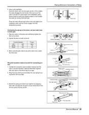
...cover where they fit into their slots(clicking sound). Bundle the piping and drain hose together by moving it left and right sides of the installation plate.) Ensure that there may be no gap. 2. Tighten the flare nut with vinyl tape. 3. Outside diameter mm inch Ø6.35... 1/4 Ø9.52 3/8 Torque kg.m 1.8 4.2 3. Bind them together with vinyl tape so that the hooks are properly seated on the installation plate by wrapping them with vinyl tape Drain hose Vinyl tape(wide) Service Manual 23 Align the center of Piping Connecting cable Drain hose Indoor...
...cover where they fit into their slots(clicking sound). Bundle the piping and drain hose together by moving it left and right sides of the installation plate.) Ensure that there may be no gap. 2. Tighten the flare nut with vinyl tape. 3. Outside diameter mm inch Ø6.35... 1/4 Ø9.52 3/8 Torque kg.m 1.8 4.2 3. Bind them together with vinyl tape so that the hooks are properly seated on the installation plate by wrapping them with vinyl tape Drain hose Vinyl tape(wide) Service Manual 23 Align the center of Piping Connecting cable Drain hose Indoor...
Service Manual
Page 24
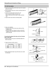
Route the indoor tubing and the drain hose to drain pipe. 1. Indoor unit installation • Hang the indoor unit from the wall. Tighten the flare nut with the cable for easy connection later. 4. Connecting the piping to the indoor ... position. 2. When extending the drain hose at the top of the indoor unit from the hooks at the indoor unit, install the drain pipe. 24 Multi type Air Conditioner Indoor unit Installation plate 8cm Spacer Indoor unit tubing Flare nut Pipes Wrench Indoor unit tubing Open-end wrench (fixed) Flare nut Connection...
Route the indoor tubing and the drain hose to drain pipe. 1. Indoor unit installation • Hang the indoor unit from the wall. Tighten the flare nut with the cable for easy connection later. 4. Connecting the piping to the indoor ... position. 2. When extending the drain hose at the top of the indoor unit from the hooks at the indoor unit, install the drain pipe. 24 Multi type Air Conditioner Indoor unit Installation plate 8cm Spacer Indoor unit tubing Flare nut Pipes Wrench Indoor unit tubing Open-end wrench (fixed) Flare nut Connection...
Service Manual
Page 25
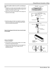
Bind them with vinyl tape so that the hooks are properly seated on the installation plate by wrapping them together with cloth tape over the range within which accommodates the rear piping housing section with vinyl tape(wide) Indoor unit installation 1. Bundle the piping and drain hose together by moving it left and... right sides of the unit against the installation plate until the hooks engage into the rear piping housing section. Remove the spacer. 2. Ensure that there may be no gap. 2. Press the lower left ...
Bind them with vinyl tape so that the hooks are properly seated on the installation plate by wrapping them together with cloth tape over the range within which accommodates the rear piping housing section with vinyl tape(wide) Indoor unit installation 1. Bundle the piping and drain hose together by moving it left and... right sides of the unit against the installation plate until the hooks engage into the rear piping housing section. Remove the spacer. 2. Ensure that there may be no gap. 2. Press the lower left ...
Service Manual
Page 27
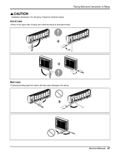
Flaring Work and Connection of clamp and unfold the tubing to the tubing. Service Manual 27 Bad case • Following bending type from right to left piping. For left may cause damage to downward slowly. Follow the instruction below. Good case • Press on the upper side of Piping Installation Information.
Flaring Work and Connection of clamp and unfold the tubing to the tubing. Service Manual 27 Bad case • Following bending type from right to left piping. For left may cause damage to downward slowly. Follow the instruction below. Good case • Press on the upper side of Piping Installation Information.
Service Manual
Page 30
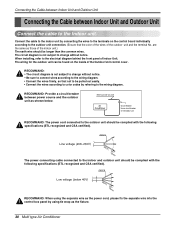
... power source Air Conditioner Circuit Breaker Use a circuit breaker or time delay fuse. are the same as those of the Outdoor Unit control cover. When installing, refer to the outdoor unit should be complied with the following specifications (ETL recognized and CSA certified). The wiring for the outdoor unit can be...
... power source Air Conditioner Circuit Breaker Use a circuit breaker or time delay fuse. are the same as those of the Outdoor Unit control cover. When installing, refer to the outdoor unit should be complied with the following specifications (ETL recognized and CSA certified). The wiring for the outdoor unit can be...
Service Manual
Page 35
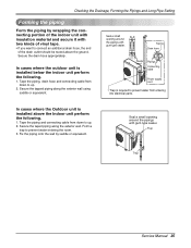
... the piping Form the piping by saddle or equivalent. Secure the tapped piping along the exterior wall. In cases where the Outdoor unit is installed below the indoor unit perform the following . 1. Taping Drain hose Plastic band Pipings Connecting cable Power supply cord • Trap is required... connecting portion of the indoor unit with insulation material and secure it with gum type sealer. In cases where the outdoor unit is installed above the ground. Trap Trap Service Manual 35 Tape the piping, drain hose and connecting cable from entering into electrical parts. Tape ...
... the piping Form the piping by saddle or equivalent. Secure the tapped piping along the exterior wall. In cases where the Outdoor unit is installed below the indoor unit perform the following . 1. Taping Drain hose Plastic band Pipings Connecting cable Power supply cord • Trap is required... connecting portion of the indoor unit with insulation material and secure it with gum type sealer. In cases where the outdoor unit is installed above the ground. Trap Trap Service Manual 35 Tape the piping, drain hose and connecting cable from entering into electrical parts. Tape ...


