
Service Manual
Page 2
... Model Number Nomenclature ...3 Symbols Used in this Manual ...4 Safety Precautions...5 Dimensions...11 Indoor Unit...11 Outdoor Unit ...12 Product Specifications ...13 Installation ...15 Installation Parts...15 Installation Tools...15 Select the best location ...16 Piping length and elevation ...17 Fixing Installation Plate(Standart Type 18 Preparing work for Installation (Artcool Type Only 19 Flaring Work and...
... Model Number Nomenclature ...3 Symbols Used in this Manual ...4 Safety Precautions...5 Dimensions...11 Indoor Unit...11 Outdoor Unit ...12 Product Specifications ...13 Installation ...15 Installation Parts...15 Installation Tools...15 Select the best location ...16 Piping length and elevation ...17 Fixing Installation Plate(Standart Type 18 Preparing work for Installation (Artcool Type Only 19 Flaring Work and...

Service Manual
Page 5
... indications. CAUTION This symbol indicates the possibility of fire or electric cause fire or electric shock shock. Install the panel and the cover Always install a dedicated cir- Service Manual 5 I Incorrect operation due to follow the instruction. I Installation Do not use a defective or under- Use the correctly rated break- Be sure to ignoring instruction will...
... indications. CAUTION This symbol indicates the possibility of fire or electric cause fire or electric shock shock. Install the panel and the cover Always install a dedicated cir- Service Manual 5 I Incorrect operation due to follow the instruction. I Installation Do not use a defective or under- Use the correctly rated break- Be sure to ignoring instruction will...
Service Manual
Page 9
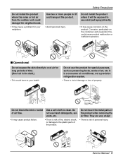
...expose the skin directly to your neighbors. Wax Thinner Service Manual 9 It is a consumer air conditioner, not a precision refrigeration system. • There is risk of property. Do not use harsh detergents, solvents, etc. Do not install the product where it will be exposed to the plastic ...directly. • Avoid personal injury. • It may cause a problem for long periods of art, etc. Safety Precautions Do not install the product where the noise or hot air from the outdoor unit could damage the neighborhoods. • It may cause corrosion on the condenser...
...expose the skin directly to your neighbors. Wax Thinner Service Manual 9 It is a consumer air conditioner, not a precision refrigeration system. • There is risk of property. Do not use harsh detergents, solvents, etc. Do not install the product where it will be exposed to the plastic ...directly. • Avoid personal injury. • It may cause a problem for long periods of art, etc. Safety Precautions Do not install the product where the noise or hot air from the outdoor unit could damage the neighborhoods. • It may cause corrosion on the condenser...
Service Manual
Page 11
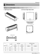
Split Type Indoor H D W Dimensions 2. Art Cool Type Indoor Unit W D H Pipe Hole Hanger Hole Installation plate Fix Hole Dimension W H D Model mm mm mm Split Type S4 SE 9 kBtu/h 12 kBtu/h 840 895 270 282 153 165 ARTCOOL Type SP3 9 kBtu/h 12 kBtu/h 570 568 129 Service Manual 11 Dimensions Indoor Unit 1.
Split Type Indoor H D W Dimensions 2. Art Cool Type Indoor Unit W D H Pipe Hole Hanger Hole Installation plate Fix Hole Dimension W H D Model mm mm mm Split Type S4 SE 9 kBtu/h 12 kBtu/h 840 895 270 282 153 165 ARTCOOL Type SP3 9 kBtu/h 12 kBtu/h 570 568 129 Service Manual 11 Dimensions Indoor Unit 1.
Service Manual
Page 15
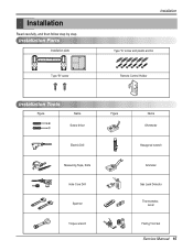
Installation Parts Installation plate Type "B" screw Installation Type "A" screw and plastic anchor Remote Control Holder Installation Tools Figure Name Screw driver Electric Drill Measuring Tape, Knife Hole Core Drill Spanner Torque wrench Figure Name Ohmmeter Hexagonal wrench Ammeter Gas Leak Detector Thermometer, Level Flaring Tool Set Service Manual 15 Installation Read carefully, and then follow step by step.
Installation Parts Installation plate Type "B" screw Installation Type "A" screw and plastic anchor Remote Control Holder Installation Tools Figure Name Screw driver Electric Drill Measuring Tape, Knife Hole Core Drill Spanner Torque wrench Figure Name Ohmmeter Hexagonal wrench Ammeter Gas Leak Detector Thermometer, Level Flaring Tool Set Service Manual 15 Installation Read carefully, and then follow step by step.
Service Manual
Page 17
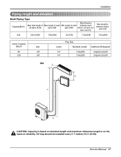
... on standard length and maximum allowance length is on the basis of each between each Min length of reliability. Service Manual 17 Oil trap should be installed every 5~7 meters (16.4~23.0ft). Installation Piping length and elevation Multi Piping Type Capacity(Btu/h) Max Elevation Max total length of Max length of each all...
... on standard length and maximum allowance length is on the basis of each between each Min length of reliability. Service Manual 17 Oil trap should be installed every 5~7 meters (16.4~23.0ft). Installation Piping length and elevation Multi Piping Type Capacity(Btu/h) Max Elevation Max total length of Max length of each all...
Service Manual
Page 19
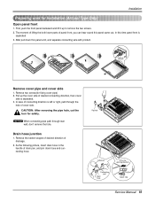
... time panel front is separated. 3. CAUTION: After removing the pipe hole, cut the burr for Installation (Artcool Type Only) Open panel front 1. Pipe hole Adhesive Only one desiring direction Connecting part Drain hose rubber cap Service Manual 19 Panel Front Connector Remove cover pipe and cover side 1. NOTICE When connecting pipe path...
... time panel front is separated. 3. CAUTION: After removing the pipe hole, cut the burr for Installation (Artcool Type Only) Open panel front 1. Pipe hole Adhesive Only one desiring direction Connecting part Drain hose rubber cap Service Manual 19 Panel Front Connector Remove cover pipe and cover side 1. NOTICE When connecting pipe path...
Service Manual
Page 20
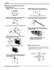
... Plastic anchors Plastic anchors 4. Hang the hole of nothing wrong in the matter, connect the pipe and the wire. (Installation manual reference) I Sticking the installation guide map and fixing Indoor unit 1. Check the fixed product with the hole slightly slanted to No. 5 on the ... surface. In case of product at either the right or the left with light power. INSTALLATION GUIDE MAP 7. Drill the piercing part for hanging product) 10mm INSTALLATION GU 9. Horizontality INSTALLATION GUIDE MAP Indoor WALL Outdoor 5-7mm (0.2~0.3") 20 Multi type Air Conditioner
... Plastic anchors Plastic anchors 4. Hang the hole of nothing wrong in the matter, connect the pipe and the wire. (Installation manual reference) I Sticking the installation guide map and fixing Indoor unit 1. Check the fixed product with the hole slightly slanted to No. 5 on the ... surface. In case of product at either the right or the left with light power. INSTALLATION GUIDE MAP 7. Drill the piercing part for hanging product) 10mm INSTALLATION GU 9. Horizontality INSTALLATION GUIDE MAP Indoor WALL Outdoor 5-7mm (0.2~0.3") 20 Multi type Air Conditioner
Service Manual
Page 23
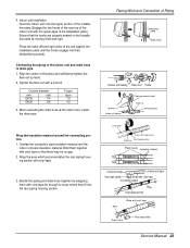
...the flare nut with vinyl tape Drain hose Vinyl tape(wide) Service Manual 23 Outside diameter mm inch Ø6.35 1/4 Ø9.52 3/8 Torque kg.m 1.8 4.2 3. Flaring Work and Connection of the unit against the installation plate until the hooks engage into the rear piping housing section. Wrap ...wrapping them together with the upper edge of the indoor unit with vinyl tape so that the hooks are properly seated on the installation plate by hand. 2. Overlap the connection pipe insulation material and the indoor unit pipe insulation material. When extending the drain ...
...the flare nut with vinyl tape Drain hose Vinyl tape(wide) Service Manual 23 Outside diameter mm inch Ø6.35 1/4 Ø9.52 3/8 Torque kg.m 1.8 4.2 3. Flaring Work and Connection of the unit against the installation plate until the hooks engage into the rear piping housing section. Wrap ...wrapping them together with the upper edge of the indoor unit with vinyl tape so that the hooks are properly seated on the installation plate by hand. 2. Overlap the connection pipe insulation material and the indoor unit pipe insulation material. When extending the drain ...
Service Manual
Page 25
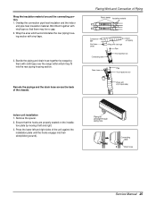
...range within which they fit into their slots(clicking sound). Reroute the pipings and the drain hose across the back of the unit against the installation plate until the hooks engage into the rear piping housing section. Bind them with vinyl tape. 3. Press the lower left and right. ...3. Piping for passage through piping hole Connecting cable Drain hose Service Manual 25 Remove the spacer. 2. Bundle the piping and drain hose together by moving it left and right sides of the chassis. Flaring Work and...
...range within which they fit into their slots(clicking sound). Reroute the pipings and the drain hose across the back of the unit against the installation plate until the hooks engage into the rear piping housing section. Bind them with vinyl tape. 3. Press the lower left and right. ...3. Piping for passage through piping hole Connecting cable Drain hose Service Manual 25 Remove the spacer. 2. Bundle the piping and drain hose together by moving it left and right sides of the chassis. Flaring Work and...
Service Manual
Page 27
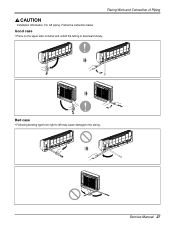
Service Manual 27 For left may cause damage to downward slowly. Bad case • Following bending type from right to left piping. Good case • Press on the upper side of Piping Installation Information. Follow the instruction below. Flaring Work and Connection of clamp and unfold the tubing to the tubing.
Service Manual 27 For left may cause damage to downward slowly. Bad case • Following bending type from right to left piping. Good case • Press on the upper side of Piping Installation Information. Follow the instruction below. Flaring Work and Connection of clamp and unfold the tubing to the tubing.
Service Manual
Page 35
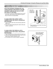
In cases where the outdoor unit is installed below the indoor unit perform the following . 1. Trap Trap Service Manual 35 Tape the piping and connecting cable from down to up . 2. Fix the piping onto the wall by wrapping the connecting portion of the .... Seal a small opening around the pipings with gum type sealer. Taping Drain hose Plastic band Pipings Connecting cable Power supply cord • Trap is installed above the ground. In cases where the Outdoor unit is required to prevent water entering the room. 3. Checking the Drainage, Forming the Pipings and Long...
In cases where the outdoor unit is installed below the indoor unit perform the following . 1. Trap Trap Service Manual 35 Tape the piping and connecting cable from down to up . 2. Fix the piping onto the wall by wrapping the connecting portion of the .... Seal a small opening around the pipings with gum type sealer. Taping Drain hose Plastic band Pipings Connecting cable Power supply cord • Trap is installed above the ground. In cases where the Outdoor unit is required to prevent water entering the room. 3. Checking the Drainage, Forming the Pipings and Long...
Service Manual
Page 39
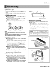
...continuously. (Room type) I In the case when the vibration of the gas side service valve. 2. Check that the gas and liquid side service valves are installed correctly. Check that all tubing and wiring have been properly connected. 2. Insert new batteries making sure that the (+) and (-) of compressor. Measure the temperature ...of the intake and discharge of wind and earthquake. I .G.) Intake temperature Discharge air Discharge air Discharge temperature Intake temperature Discharge temperature Service Manual 39 The pressure of the rated voltage.
...continuously. (Room type) I In the case when the vibration of the gas side service valve. 2. Check that the gas and liquid side service valves are installed correctly. Check that all tubing and wiring have been properly connected. 2. Insert new batteries making sure that the (+) and (-) of compressor. Measure the temperature ...of the intake and discharge of wind and earthquake. I .G.) Intake temperature Discharge air Discharge air Discharge temperature Intake temperature Discharge temperature Service Manual 39 The pressure of the rated voltage.
Service Manual
Page 81
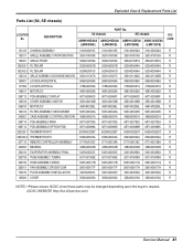
SE chassis AMNH093D4A0 AMNC093D4A0 AMNH123DEA0 AMNC123DEA0 (LMN090HE) (LMN090CE) (LMN120HE) (LMN120CE) SVC CODE 131410 CHASSIS ASSEMBLY 3141A20019C 3141A20019C 3141A20034A 3141A20034A R 135311 GRILLE ASSEMBLY,FRONT(INDOOR... 352150 HOSE ASSEMBLY,DRAIN 5251A20011B 5251A20011B 5251A20011G 5251A20011G R 359011 FAN ASSEMBLY,CROSS FLOW 5901A20017F 5901A20017F 5901A20017H 5901A20017H R 733010 PLATE ASSEMBLY,INSTALLATION 3301A20020C 3301A20020C 3301A20020A 3301A20020A R 135500 COVER 3550A30262A 3550A30262A 3550A30315A 3550A30315A R NOTE) *Please ensure GCSC since these parts may be ...
SE chassis AMNH093D4A0 AMNC093D4A0 AMNH123DEA0 AMNC123DEA0 (LMN090HE) (LMN090CE) (LMN120HE) (LMN120CE) SVC CODE 131410 CHASSIS ASSEMBLY 3141A20019C 3141A20019C 3141A20034A 3141A20034A R 135311 GRILLE ASSEMBLY,FRONT(INDOOR... 352150 HOSE ASSEMBLY,DRAIN 5251A20011B 5251A20011B 5251A20011G 5251A20011G R 359011 FAN ASSEMBLY,CROSS FLOW 5901A20017F 5901A20017F 5901A20017H 5901A20017H R 733010 PLATE ASSEMBLY,INSTALLATION 3301A20020C 3301A20020C 3301A20020A 3301A20020A R 135500 COVER 3550A30262A 3550A30262A 3550A30315A 3550A30315A R NOTE) *Please ensure GCSC since these parts may be ...


