
Owner's Manual
Page 5
...the following : • Reorient the receiving antenna of the radio or television. • Relocate the Microwave Oven with the provided installation instructions. • This appliance should be boiling due to correct such interference. 5 Do not cook anything directly on a microwavable ...reduce the risk of the user to surface tension of the following items in the microwave oven: whole eggs in a residential installation. SAVE THESE INSTRUCTIONS FEDERAL COMMUNICATIONS COMMISSION RADIO FREQUENCY INTERFERENCE STATEMENT ( U.S.A. However, there is encouraged to try to correct the ...
...the following : • Reorient the receiving antenna of the radio or television. • Relocate the Microwave Oven with the provided installation instructions. • This appliance should be boiling due to correct such interference. 5 Do not cook anything directly on a microwavable ...reduce the risk of the user to surface tension of the following items in the microwave oven: whole eggs in a residential installation. SAVE THESE INSTRUCTIONS FEDERAL COMMUNICATIONS COMMISSION RADIO FREQUENCY INTERFERENCE STATEMENT ( U.S.A. However, there is encouraged to try to correct the ...

Owner's Manual
Page 6
... 297/8" x 173/4" x 173/4" 2.0 Cu.ft 71 lbs. This appliance has a short power supply cord to operate on the circuit. See the separate Installation Instructions for directions on the oven front as shown in the cord. Keep the electrical power cord dry and do not understand the grounding instructions... or if you wonder whether the appliance is properly installed and grounded. Put the plug into an outlet that is properly grounded. The number is designed to reduce the risk of your microwave...
... 297/8" x 173/4" x 173/4" 2.0 Cu.ft 71 lbs. This appliance has a short power supply cord to operate on the circuit. See the separate Installation Instructions for directions on the oven front as shown in the cord. Keep the electrical power cord dry and do not understand the grounding instructions... or if you wonder whether the appliance is properly installed and grounded. Put the plug into an outlet that is properly grounded. The number is designed to reduce the risk of your microwave...

Owner's Manual
Page 11
... the WARMING for 2 minutes. 1. MAC & CHEESE, HOT DOG, CHICKEN NUGGETS. NOTE: • The"WARMING" feature keeps food warm by the heating element and the fan installed on a dinner plate can keep food warm at the same time. WARMING TABLE Example: To set and start microwave cooking without needing to touch the...
... the WARMING for 2 minutes. 1. MAC & CHEESE, HOT DOG, CHICKEN NUGGETS. NOTE: • The"WARMING" feature keeps food warm by the heating element and the fan installed on a dinner plate can keep food warm at the same time. WARMING TABLE Example: To set and start microwave cooking without needing to touch the...

Owner's Manual
Page 27
... months. 1. Remove the lamp cover mounting screws. 3. Slide the grille left and tip forward, then lift out to recirculate air, the charcoal filter (5230W1A003C) is installed to remove. OVEN LIGHT WARMING LAMP LIGHT 5. mounting screws. Turn the power back on at your microwave hood combination is available by calling the Parts...
... months. 1. Remove the lamp cover mounting screws. 3. Slide the grille left and tip forward, then lift out to recirculate air, the charcoal filter (5230W1A003C) is installed to remove. OVEN LIGHT WARMING LAMP LIGHT 5. mounting screws. Turn the power back on at your microwave hood combination is available by calling the Parts...

Owner's Manual
Page 29
... followed. If food is overcooked • check recipe to be sure all directions (amount, power level, time, size of aluminum foil strips used ) is properly installed on up to an hour to prevent overcooking.
... followed. If food is overcooked • check recipe to be sure all directions (amount, power level, time, size of aluminum foil strips used ) is properly installed on up to an hour to prevent overcooking.

Owner's Manual
Page 31
... to the original purchaser of the product and effective only when used in the Operating Guide, accident, vermin, fire, flood, improper installation, acts of God, unauthorized modification or alteration, incorrect electrical current or voltage, or commercial use, or use , during the warranty ...are warranted for other rights that result from the date of original consumer purchase of Purchase*. USA Model: LMHM2017SB / LMHM2017SW / LMHM2017ST / LSMH207ST LG Electronics Inc. Or visit our website at : http://us .lgservice.com Replacement Units and Repair Parts are answered 24 hours a ...
... to the original purchaser of the product and effective only when used in the Operating Guide, accident, vermin, fire, flood, improper installation, acts of God, unauthorized modification or alteration, incorrect electrical current or voltage, or commercial use, or use , during the warranty ...are warranted for other rights that result from the date of original consumer purchase of Purchase*. USA Model: LMHM2017SB / LMHM2017SW / LMHM2017ST / LSMH207ST LG Electronics Inc. Or visit our website at : http://us .lgservice.com Replacement Units and Repair Parts are answered 24 hours a ...

Installation Instructions
Page 1
EE INSTALLATION INSTRUCTIONS PLEASE READ AND SAVETHESE INSTALLATIONINSTRUCTIONS. P/NO.: M FL06208704 http://us.lgservice.com !
EE INSTALLATION INSTRUCTIONS PLEASE READ AND SAVETHESE INSTALLATIONINSTRUCTIONS. P/NO.: M FL06208704 http://us.lgservice.com !

Installation Instructions
Page 2
... on the front of microwave oven. Before you drill into the wall, note where electrical outlets are and where electrical wires might be installed or located by installing this oven. BE SURE TO READ THE FOLLOWING SAFETY iNSTRUCTiONS: Model Number Plate Mounting Plate Model Number Plate Figure 1 Mounting Plate Figure... 2 AWARNINGA For Your Safety • This oven should not be behind doon See Figure 1. YOUR SAFETY FIRST BEFORE YOU START • Proper installation is located on back side of oven, behind concealed in the cabinet above the microwave as close as possible to...
... on the front of microwave oven. Before you drill into the wall, note where electrical outlets are and where electrical wires might be installed or located by installing this oven. BE SURE TO READ THE FOLLOWING SAFETY iNSTRUCTiONS: Model Number Plate Mounting Plate Model Number Plate Figure 1 Mounting Plate Figure... 2 AWARNINGA For Your Safety • This oven should not be behind doon See Figure 1. YOUR SAFETY FIRST BEFORE YOU START • Proper installation is located on back side of oven, behind concealed in the cabinet above the microwave as close as possible to...

Installation Instructions
Page 3
.... GROUNDED OUTLET • DO NOT, UNDER ANY CIRCUMSTANCES, REMOVE THE POWER SUPPLY CORD GROUNDING PRONG! Check with a grounding plug. • Place the plug into a properly installed and grounded outlet. DO NOT try to excessive microwave energy. -3- DO NOT operate the microwave oven if it . DO NOT USE THE MICROWAVE OVEN: •...
.... GROUNDED OUTLET • DO NOT, UNDER ANY CIRCUMSTANCES, REMOVE THE POWER SUPPLY CORD GROUNDING PRONG! Check with a grounding plug. • Place the plug into a properly installed and grounded outlet. DO NOT try to excessive microwave energy. -3- DO NOT operate the microwave oven if it . DO NOT USE THE MICROWAVE OVEN: •...

Installation Instructions
Page 4
... AND SUPPORT. - DO NOT mount the microwave oven to protect these surfaces could result in property damage. -4- BE SURE you begin installing the oven, PLACE A PIECE OF THE CARTON OR OTHER HEAVY MATERIAL (a blanket) over the countertop or cooktop to protect it is...cabinet) 1 Power Suf 3lyCord Hole 30"rain.cabineotpening width > 30"rain.clearancferombottom ofcabinetto cooking surface or countertop beforeinstallation. (Use templates included with installation instructions) Figure 4 CAUTION • Before you have enough space. Failure to an island or peninsula cabinet. - BE SURE the upper ...
... AND SUPPORT. - DO NOT mount the microwave oven to protect these surfaces could result in property damage. -4- BE SURE you begin installing the oven, PLACE A PIECE OF THE CARTON OR OTHER HEAVY MATERIAL (a blanket) over the countertop or cooktop to protect it is...cabinet) 1 Power Suf 3lyCord Hole 30"rain.cabineotpening width > 30"rain.clearancferombottom ofcabinetto cooking surface or countertop beforeinstallation. (Use templates included with installation instructions) Figure 4 CAUTION • Before you have enough space. Failure to an island or peninsula cabinet. - BE SURE the upper ...

Installation Instructions
Page 5
... cord) Actual Size Two power cord clamp bushings - weight requirement.T -5- Actual Size (for the toggle bolts) One rear wail template- Actual Size (for securing to install at least two lag screws into a 2" x 4" stud and four anchor bolts into the wall. Actual Size (for roof venting or wall venting...
... cord) Actual Size Two power cord clamp bushings - weight requirement.T -5- Actual Size (for the toggle bolts) One rear wail template- Actual Size (for securing to install at least two lag screws into a 2" x 4" stud and four anchor bolts into the wall. Actual Size (for roof venting or wall venting...

Installation Instructions
Page 6
...the counter top. PAR TS, TO 0 L S, MATER IA LS You will need special hardware and tools. o The ductwork you will need for the installation is not included. Measuring Tape Plumb Line Small Side Cutters or Tin Snips Duct Tape Gloves Caulking Gun o If you have a back-draft damper. (Shown... on page 5). -6- All wall and roof caps must have brick or masonry walls, you need the following tools and materials for the installation: Carton or other heaw material for the power cord hole) Electric Drill 3/8" and 3/4" wood drill bits 1/2" and 3/16" drill bits ---,=,=====.
...the counter top. PAR TS, TO 0 L S, MATER IA LS You will need special hardware and tools. o The ductwork you will need for the installation is not included. Measuring Tape Plumb Line Small Side Cutters or Tin Snips Duct Tape Gloves Caulking Gun o If you have a back-draft damper. (Shown... on page 5). -6- All wall and roof caps must have brick or masonry walls, you need the following tools and materials for the installation: Carton or other heaw material for the power cord hole) Electric Drill 3/8" and 3/4" wood drill bits 1/2" and 3/16" drill bits ---,=,=====.

Installation Instructions
Page 7
... extension cord. Grounded Outlet TQ (Inside Cabinet) Power=Supply=Cord Hole Figure 5 AWARNINGA improper grounding could result in Figure 5) later when you MUST have one installed by a qualified electrician. 2. NOTE: The outlet should be grounded! -7- Keep the power cord dry and do not have the proper wall outlet, you prepare the...
... extension cord. Grounded Outlet TQ (Inside Cabinet) Power=Supply=Cord Hole Figure 5 AWARNINGA improper grounding could result in Figure 5) later when you MUST have one installed by a qualified electrician. 2. NOTE: The outlet should be grounded! -7- Keep the power cord dry and do not have the proper wall outlet, you prepare the...

Installation Instructions
Page 8
...-wall Figure 6 Roof Venting 3 1/4"x10" duct roof cap _._ oven Roof _, venting through-the-roof Figure 7 REMEMBER AS YOU INSTALL THE VENTING: • Keep the length of the ductwork the same. • Do not install two elbows together. • Use duct tape to ventilate your oven efficiently. See examples on page 9. • Keep...
...-wall Figure 6 Roof Venting 3 1/4"x10" duct roof cap _._ oven Roof _, venting through-the-roof Figure 7 REMEMBER AS YOU INSTALL THE VENTING: • Keep the length of the ductwork the same. • Do not install two elbows together. • Use duct tape to ventilate your oven efficiently. See examples on page 9. • Keep...

Installation Instructions
Page 9
... is round, you must not exceed the equivalent of 140 feet. For best performance, do not use a rectangular-to-round adapter, with a rectangular 3" extension duct installed between the damper assembly and the adapter to 6"=5ft. 3 1/4" x 10" roof cap=24ft. 3 1/4,,x 10,, 90_ elbow=25ft. 7 90°elbow =1 Oft. 3 1/4" x 10" wall cap =40ft...
... is round, you must not exceed the equivalent of 140 feet. For best performance, do not use a rectangular-to-round adapter, with a rectangular 3" extension duct installed between the damper assembly and the adapter to 6"=5ft. 3 1/4" x 10" roof cap=24ft. 3 1/4,,x 10,, 90_ elbow=25ft. 7 90°elbow =1 Oft. 3 1/4" x 10" wall cap =40ft...

Installation Instructions
Page 10
...the blower assembled for room venting, if you want wall=venting or roof=vented installation, you can get closer to distort the plate. Remove The Mounting Plate: 1. See Figure 12. 2. Room-Vented (recirculating)Installation: This oven is shipped with a thick, protective covering to cut and remove ...(s) (1 or 2 screws) from the mounting plate as the rear mounting plate. (It will be used as shown and discard. Wall-Vented Installation: 1. Remove one blower unit mounting screw and one or two blower plate screw(s). Carefully lift the blower unit out of personal injury, wear protective...
...the blower assembled for room venting, if you want wall=venting or roof=vented installation, you can get closer to distort the plate. Remove The Mounting Plate: 1. See Figure 12. 2. Room-Vented (recirculating)Installation: This oven is shipped with a thick, protective covering to cut and remove ...(s) (1 or 2 screws) from the mounting plate as the rear mounting plate. (It will be used as shown and discard. Wall-Vented Installation: 1. Remove one blower unit mounting screw and one or two blower plate screw(s). Carefully lift the blower unit out of personal injury, wear protective...
Installation Instructions
Page 11
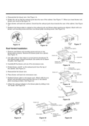
.... 5.Rotatteheunist othatheexhausptortsfacethereaor fthecabineSt.eeFigur1e7.Whenyouinserbt loweurnit, blowewr iremusbt elikefigure16. 6.P17la.cebloweurnibt ackintocabineCt.hectkhattheexhausptortsfacetowardtsherearofthecabineSt.eeFigure 7.ReattacthebloweprlatetocabinestotheexhausptortsandbloweprlateopeninagrealignedA.ttacwh ithone bloweurnitmountinsgcrewandthenonebloweprlatemountinsgcrewS. blower unit Figure 15 Roof-Vented Installation: exhaust ports Figure 16 exhaust ports Figure 17 blower plate ___ m£unting screw (option) 1. blower unit mounting screw (option) Figure 23 -11...
.... 5.Rotatteheunist othatheexhausptortsfacethereaor fthecabineSt.eeFigur1e7.Whenyouinserbt loweurnit, blowewr iremusbt elikefigure16. 6.P17la.cebloweurnibt ackintocabineCt.hectkhattheexhausptortsfacetowardtsherearofthecabineSt.eeFigure 7.ReattacthebloweprlatetocabinestotheexhausptortsandbloweprlateopeninagrealignedA.ttacwh ithone bloweurnitmountinsgcrewandthenonebloweprlatemountinsgcrewS. blower unit Figure 15 Roof-Vented Installation: exhaust ports Figure 16 exhaust ports Figure 17 blower plate ___ m£unting screw (option) 1. blower unit mounting screw (option) Figure 23 -11...

Installation Instructions
Page 12
STEP 4: PREPARE THE WALL & UPPER CABINET AWARNINGA To avoid personal injury or property damage, do not attempt to install this microwave oven if you cannot find any wall stud, consult a local building contractor. 3. NOTE: Be sure the minimum width is 30 inches and the ...
STEP 4: PREPARE THE WALL & UPPER CABINET AWARNINGA To avoid personal injury or property damage, do not attempt to install this microwave oven if you cannot find any wall stud, consult a local building contractor. 3. NOTE: Be sure the minimum width is 30 inches and the ...

Installation Instructions
Page 13
...the power supply cord bushing. Complete whichever venting system you have chosen. Use caulking compound to any electrical circuits that could be affected by installing this oven. WARNING To avoid risk of personal injury, electrical shock or death, cover the edge of the power supply cord hole with ...3/16" hole for toggle screws. Drill a 1/2" hole at the marks. , Align filler blocks over the two openings in the plate. Make sure to STEP 5, INSTALL THE MOUNTING PLATE, located on page 14. 5. If there is no stud, drill a 3/4" hole for lag screws. Cut out the shaded area marked F on the...
...the power supply cord bushing. Complete whichever venting system you have chosen. Use caulking compound to any electrical circuits that could be affected by installing this oven. WARNING To avoid risk of personal injury, electrical shock or death, cover the edge of the power supply cord hole with ...3/16" hole for toggle screws. Drill a 1/2" hole at the marks. , Align filler blocks over the two openings in the plate. Make sure to STEP 5, INSTALL THE MOUNTING PLATE, located on page 14. 5. If there is no stud, drill a 3/4" hole for lag screws. Cut out the shaded area marked F on the...

Installation Instructions
Page 14
...holes for toggle bolts. If there is no stud, drill a 5/8 hole for proper installation. To use at holes A, B, C and D. Tighten all bolts. m on the circles. Four holes must be used , the installation will not be attached to the mounting plate. See the next page on how to .../ Mounting #i Plate ,/ / 1 Draw Lines i on the wall. 2. Line up with one of the bottom holes to prepare the rear wall cutout opening for studs. Installer must be secure. If there is a stud, drill a 3/16 hole for wall-vented. 3. Insert the bolts into the holes in the wall to 3/4 past the...
...holes for toggle bolts. If there is no stud, drill a 5/8 hole for proper installation. To use at holes A, B, C and D. Tighten all bolts. m on the circles. Four holes must be used , the installation will not be attached to the mounting plate. See the next page on how to .../ Mounting #i Plate ,/ / 1 Draw Lines i on the wall. 2. Line up with one of the bottom holes to prepare the rear wall cutout opening for studs. Installer must be secure. If there is a stud, drill a 3/16 hole for wall-vented. 3. Insert the bolts into the holes in the wall to 3/4 past the...


