
Service Manual
Page 2
REPLACEMENT PARTS LIST 28 -2- TROUBLESHOOTING GUIDE 20 5. CONTENTS 1. DISASSEMBLY INSTRUCTIONS 3.1 MECHANICAL PARTS ...13 3.1.1 BUCKET AND AIR FILTER ...13 3.1.2 FRONT CASE AND TOP COVER 13 3.1.3 CABINET AND CONTROL BOX ...13 3.2 CONTROL PARTS ...14 3.2.1 POWER CORD ASSEMBLY ...14 3.2.2 SENSOR ASSEMBLY ...14 3.2.3 PWB(PCB) ASSEMBLY, MAIN ...14 3.2.4 CAPACITOR...14 3.2.5 MICRO SWITCH ASSEMBLY ...14 3.2.6 COIL ASSEMBLY, SOLENOID ...15 3.2.7 CONTROL PANEL ...15 3.2.8 FAN AND MOTOR...16 3.2.9 DRAIN PAN ...16 3.3 REFRIGERATING CYCLE ...17 3.3.1 CONDENSER, EVAPORATOR AND CAPILLARY TUBE ...
REPLACEMENT PARTS LIST 28 -2- TROUBLESHOOTING GUIDE 20 5. CONTENTS 1. DISASSEMBLY INSTRUCTIONS 3.1 MECHANICAL PARTS ...13 3.1.1 BUCKET AND AIR FILTER ...13 3.1.2 FRONT CASE AND TOP COVER 13 3.1.3 CABINET AND CONTROL BOX ...13 3.2 CONTROL PARTS ...14 3.2.1 POWER CORD ASSEMBLY ...14 3.2.2 SENSOR ASSEMBLY ...14 3.2.3 PWB(PCB) ASSEMBLY, MAIN ...14 3.2.4 CAPACITOR...14 3.2.5 MICRO SWITCH ASSEMBLY ...14 3.2.6 COIL ASSEMBLY, SOLENOID ...15 3.2.7 CONTROL PANEL ...15 3.2.8 FAN AND MOTOR...16 3.2.9 DRAIN PAN ...16 3.3 REFRIGERATING CYCLE ...17 3.3.1 CONDENSER, EVAPORATOR AND CAPILLARY TUBE ...
Service Manual
Page 3
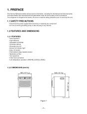
...; Removable & large capacity bucket. • Washable air filter • Two-speed fan • Drain hose connection. • Low temperature operation (DH504EL/LD50EL/LD65EL) 1.2.2 DIMENSIONS (mm/in) 385 (15 5/32) Continuous On. 4Hr. This dehumidifier was manufactured and assembled under the strict quality control procedures. The refrigerant is charged at the factory. On/Off High Low TIMER FAN SPEED AUTO RESTART HUMIDITY SETTING HUMIDITY CONTROL BUCKET FULL POWER ENERGY STAR 340 (13 3/8) 540 (21 1/4) Figure 1 -3- PREFACE This Service Manual provides...
...; Removable & large capacity bucket. • Washable air filter • Two-speed fan • Drain hose connection. • Low temperature operation (DH504EL/LD50EL/LD65EL) 1.2.2 DIMENSIONS (mm/in) 385 (15 5/32) Continuous On. 4Hr. This dehumidifier was manufactured and assembled under the strict quality control procedures. The refrigerant is charged at the factory. On/Off High Low TIMER FAN SPEED AUTO RESTART HUMIDITY SETTING HUMIDITY CONTROL BUCKET FULL POWER ENERGY STAR 340 (13 3/8) 540 (21 1/4) Figure 1 -3- PREFACE This Service Manual provides...
Service Manual
Page 4
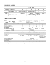
....9) 17.6(38.9) 20.4(44.9) 22.2(48.9) *NOTE:Specifications are subject to minor change without notice for further improvement. -4- DH300EY5 DH404Y5 DH504ELY5 LD65ELY5 DH400EY5,LD40EY5 LD50ELY5 1.4 SPECIFICATIONS ITEMS MODELS POWER SUPPLY(Phase,V,Hz) INPUT(W) RUNNING CURRENT(A) ENERGY FACTOR(L/kw.h) REFRIGERANT REFRIGERANT CHARGE, oz(g) OPEN THERMISTOR CLOSE SOLENOID VALVE* COMPRESSOR MODEL No. 1.3 MODEL NAMES CAPACITY (Pints/24hrs) CONTROL PANEL MECHANICAL TYPE ELECTRONIC TYPE MODEL NAME 30 40 50 65 DH305Y5, DH300MY5...
....9) 17.6(38.9) 20.4(44.9) 22.2(48.9) *NOTE:Specifications are subject to minor change without notice for further improvement. -4- DH300EY5 DH404Y5 DH504ELY5 LD65ELY5 DH400EY5,LD40EY5 LD50ELY5 1.4 SPECIFICATIONS ITEMS MODELS POWER SUPPLY(Phase,V,Hz) INPUT(W) RUNNING CURRENT(A) ENERGY FACTOR(L/kw.h) REFRIGERANT REFRIGERANT CHARGE, oz(g) OPEN THERMISTOR CLOSE SOLENOID VALVE* COMPRESSOR MODEL No. 1.3 MODEL NAMES CAPACITY (Pints/24hrs) CONTROL PANEL MECHANICAL TYPE ELECTRONIC TYPE MODEL NAME 30 40 50 65 DH305Y5, DH300MY5...
Service Manual
Page 5
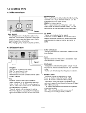
... power is removed or not placed in the room. • Press button to raise the humidity setting. • Press button to 5 or 6. Humidity Control • When you first use the dehumidifier, turn the humidity control to a lower setting. 1.5 CONTROL TYPE 1.5.1 Mechanical type Auto Shut-Off 5 4 6 3 7 2 8 1 9 Off Max Humidity Control High Low Fan Speed Figure 2 Auto Shut-Off • This light glows when the bucket is full, or when the bucket is restored. In these cases the Water Level Control Switch shuts...
... power is removed or not placed in the room. • Press button to raise the humidity setting. • Press button to 5 or 6. Humidity Control • When you first use the dehumidifier, turn the humidity control to a lower setting. 1.5 CONTROL TYPE 1.5.1 Mechanical type Auto Shut-Off 5 4 6 3 7 2 8 1 9 Off Max Humidity Control High Low Fan Speed Figure 2 Auto Shut-Off • This light glows when the bucket is full, or when the bucket is restored. In these cases the Water Level Control Switch shuts...
Service Manual
Page 6
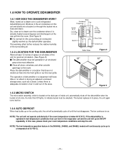
..., automatically shuts off until the frost disappears. NOTE: The low temperature operation feature in its place, the unit again turns itself on. 1.6.4 AUTO DEFROST When frost builds up on this case, please check your room temperature conditions and stop the unit. The bucket replaces in the DH504EL, DH50EL and DH65EL models will automatically cycle off the dehumidifier when the bucket is drawn over a cold refrigerated dehumidifying coil. In this coil and drains...
..., automatically shuts off until the frost disappears. NOTE: The low temperature operation feature in its place, the unit again turns itself on. 1.6.4 AUTO DEFROST When frost builds up on this case, please check your room temperature conditions and stop the unit. The bucket replaces in the DH504EL, DH50EL and DH65EL models will automatically cycle off the dehumidifier when the bucket is drawn over a cold refrigerated dehumidifying coil. In this coil and drains...
Service Manual
Page 7
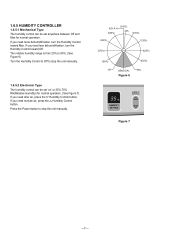
If you need less dehumidification, turn the Humidity Control toward Off. The relative humidity range is from 20% to 80%. (See Figure 6) Turn the Humidity Control to Off to stop the unit manually. 1.6.5.2 Electronic Type The humidity control can be set anywhere between Off and Max for normal operation. (See Figure 7) If you need drier air, press the Humidity Control button. If you need more dehumidification, turn the Humidity Control toward Max. Press the Power button to stop the unit...
If you need less dehumidification, turn the Humidity Control toward Off. The relative humidity range is from 20% to 80%. (See Figure 6) Turn the Humidity Control to Off to stop the unit manually. 1.6.5.2 Electronic Type The humidity control can be set anywhere between Off and Max for normal operation. (See Figure 7) If you need drier air, press the Humidity Control button. If you need more dehumidification, turn the Humidity Control toward Max. Press the Power button to stop the unit...
Service Manual
Page 9
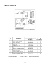
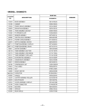
DESCRIPTION 1 POWER CORD ASSEMBLY 2 MOTOR ASSEMBLY 3 CAPACITOR 4 COMPRESSOR, SET 5 OLP 6 PWB(PCB) ASSEMBLY, DISPLAY 7 SENSOR ASSEMBLY 8 SWITCH ASSEMBLY, MICRO 9 PWB(PCB) ASSEMBLY, MAIN PART NO. DH300EY5 6411A20001Z 4681A20040Q 0CZZA20005J 2520UCBS005 6750U-L082A 6871A20482A 6877A30013L 6600A30003C 6871A10141A Q'TY REPER SET MARKS 1 S 1 S 1 S 1 S 1 S 1 S 1 S 1 S 1 S S: SERVICE PARTS A: ALTERNATE PARTS N: NOT SERVICE PARTS -9- • MODEL : DH300EY5 NO.
DESCRIPTION 1 POWER CORD ASSEMBLY 2 MOTOR ASSEMBLY 3 CAPACITOR 4 COMPRESSOR, SET 5 OLP 6 PWB(PCB) ASSEMBLY, DISPLAY 7 SENSOR ASSEMBLY 8 SWITCH ASSEMBLY, MICRO 9 PWB(PCB) ASSEMBLY, MAIN PART NO. DH300EY5 6411A20001Z 4681A20040Q 0CZZA20005J 2520UCBS005 6750U-L082A 6871A20482A 6877A30013L 6600A30003C 6871A10141A Q'TY REPER SET MARKS 1 S 1 S 1 S 1 S 1 S 1 S 1 S 1 S 1 S S: SERVICE PARTS A: ALTERNATE PARTS N: NOT SERVICE PARTS -9- • MODEL : DH300EY5 NO.
Service Manual
Page 11
• MODEL : DH404EY5/DH400EY5/LD40EY5 NO. DESCRIPTION 1 POWER CORD ASSEMBLY 2 MOTOR ASSEMBLY 3 CAPACITOR 4 COMPRESSOR,SET 5 OLP 6 PWB(PCB) ASSEMBLY,DISPLAY 7 SENSOR ASSEMBLY 8 SWITCH ASSEMBLY,MICRO 9 PWB(PCB) ASSEMBLY,MAIN PART NO. DH404EY5/DH400EY5 LD40EY5 6411A20001Z 4681A20040J 0CZZA20005N 2520UCAS003 6750U-L103A 6871A20482A 6877A30013M 6600A30003C 6871A10141A S: SERVICE PARTS A: ALTERNATE PARTS N: NOT SERVICE PARTS -11- Q'TY REPER SET MARKS 1 S 1 S 1 S 1 S 1 S 1 S 1 S 1 S 1 S
• MODEL : DH404EY5/DH400EY5/LD40EY5 NO. DESCRIPTION 1 POWER CORD ASSEMBLY 2 MOTOR ASSEMBLY 3 CAPACITOR 4 COMPRESSOR,SET 5 OLP 6 PWB(PCB) ASSEMBLY,DISPLAY 7 SENSOR ASSEMBLY 8 SWITCH ASSEMBLY,MICRO 9 PWB(PCB) ASSEMBLY,MAIN PART NO. DH404EY5/DH400EY5 LD40EY5 6411A20001Z 4681A20040J 0CZZA20005N 2520UCAS003 6750U-L103A 6871A20482A 6877A30013M 6600A30003C 6871A10141A S: SERVICE PARTS A: ALTERNATE PARTS N: NOT SERVICE PARTS -11- Q'TY REPER SET MARKS 1 S 1 S 1 S 1 S 1 S 1 S 1 S 1 S 1 S
Service Manual
Page 12
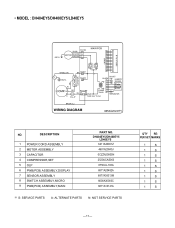
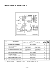
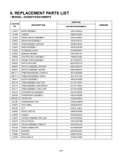
...PART NO. DH504ELY5/LD50ELY5 LD65ELY5 1 POWER CORD ASSEMBLY 6411A20001Z 2 MOTOR ASSEMBLY 4681A20040J 4681A20040K 3 CAPACITOR 0CZZA20005J 0CZZA20005J 4 COMPRESSOR (ROTARY), SET 2520UCBA010 2520UCBA007 5 OLP. 6750U-L001A 6750U-L048A 6 PWB(PCB) ASSEMBLY, DISPLAY 6871A20482A 7 SENSOR ASSEMBLY 6877A30013L 8 SWITCH ASSEMBLY, MICRO 6600A30003C 9 PWB(PCB) ASSEMBLY, MAIN 6871A10141C 10 COIL ASSEMBLY, SOLENOID 6421A20003K S: SERVICE PARTS A: ALTERNATE PARTS N: NOT SERVICE PARTS Q'TY REPER SET MARKS 1 S 1 S 1 S 1 S 1 S 1 S 1 S 1 S 1 S 1 S -12- • MODEL...
...PART NO. DH504ELY5/LD50ELY5 LD65ELY5 1 POWER CORD ASSEMBLY 6411A20001Z 2 MOTOR ASSEMBLY 4681A20040J 4681A20040K 3 CAPACITOR 0CZZA20005J 0CZZA20005J 4 COMPRESSOR (ROTARY), SET 2520UCBA010 2520UCBA007 5 OLP. 6750U-L001A 6750U-L048A 6 PWB(PCB) ASSEMBLY, DISPLAY 6871A20482A 7 SENSOR ASSEMBLY 6877A30013L 8 SWITCH ASSEMBLY, MICRO 6600A30003C 9 PWB(PCB) ASSEMBLY, MAIN 6871A10141C 10 COIL ASSEMBLY, SOLENOID 6421A20003K S: SERVICE PARTS A: ALTERNATE PARTS N: NOT SERVICE PARTS Q'TY REPER SET MARKS 1 S 1 S 1 S 1 S 1 S 1 S 1 S 1 S 1 S 1 S -12- • MODEL...
Service Manual
Page 13
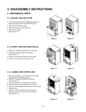
...) 3.1.3. DISASSEMBLY INSTRUCTIONS 3.1 MECHANICAL PARTS 3.1.1 BUCKET AND AIR FILTER 1. Pull out the air filter. (See Figure 10) Figure 9 3.1.2 FRONT CASE AND REAR GRILLE 1. Remove 1 screws that secure the rear grille. 4. Turn the Humidity Control off(Mechanical type) or press the power button off. (Electronic type) 2. Remove 6 screws that fasten Control box. (See Figure 13) 3. Remove 1 screw that fasten control box and unhook control box from the base.(See Figure 13) 5. Remove the Bucket, the Air filter and...
...) 3.1.3. DISASSEMBLY INSTRUCTIONS 3.1 MECHANICAL PARTS 3.1.1 BUCKET AND AIR FILTER 1. Pull out the air filter. (See Figure 10) Figure 9 3.1.2 FRONT CASE AND REAR GRILLE 1. Remove 1 screws that secure the rear grille. 4. Turn the Humidity Control off(Mechanical type) or press the power button off. (Electronic type) 2. Remove 6 screws that fasten Control box. (See Figure 13) 3. Remove 1 screw that fasten control box and unhook control box from the base.(See Figure 13) 5. Remove the Bucket, the Air filter and...
Service Manual
Page 15
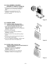
... PWB(PCB) ASSEMBLY, DISPLAY after turning over both sides of rocker switch. 6. Figure 19 ENERGY STAR ShuAt-uOtfof Off Humidity ControMl ax Fan Speed High Low Figure 20 Figure 21 Disconnect housing and all leads of the display cover. 3.2.6.2 CONTROL PANEL - Mechanical Type (DH305Y5/DH300MY5/DH400MY5/LD40Y5) 1. Remove the knob of the rotary switch by pushing the hooks on the both hooks of the rocker switch, SWITCH ASSEMBLY, ROTARY...
... PWB(PCB) ASSEMBLY, DISPLAY after turning over both sides of rocker switch. 6. Figure 19 ENERGY STAR ShuAt-uOtfof Off Humidity ControMl ax Fan Speed High Low Figure 20 Figure 21 Disconnect housing and all leads of the display cover. 3.2.6.2 CONTROL PANEL - Mechanical Type (DH305Y5/DH300MY5/DH400MY5/LD40Y5) 1. Remove the knob of the rotary switch by pushing the hooks on the both hooks of the rocker switch, SWITCH ASSEMBLY, ROTARY...
Service Manual
Page 18
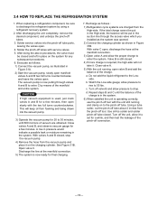
... discharge the refrigerant system by means of the charge. d. Close valve A. 5) With the unit running and clamp on the charging cylinder. Turn off tool. If the total charge cannot be put in the system. 6) When satisfied the unit is required, the high-side will not take it. a. When replacing a refrigeration component, be sure to set for a few...
... discharge the refrigerant system by means of the charge. d. Close valve A. 5) With the unit running and clamp on the charging cylinder. Turn off tool. If the total charge cannot be put in the system. 6) When satisfied the unit is required, the high-side will not take it. a. When replacing a refrigeration component, be sure to set for a few...
Service Manual
Page 20
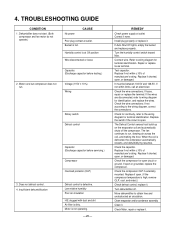
.../or condenser assembly Clean it . Low relative humidity Poor air circulation H/E clogged with dust and dirt Air filter is not operating. -20- Motor is dirty. Turn the humidity control switch toward Max. Replace if shorted, open or grounded, replace the compressor. The fan continues to wiring diagram for terminal identification. When the coil is at Off position Wire disconnected or loose Capacitor. (Discharge capacitor before servicing.) Compressor Overload protector (OLP) Defrost control is high, remove OLP, cool...
.../or condenser assembly Clean it . Low relative humidity Poor air circulation H/E clogged with dust and dirt Air filter is not operating. -20- Motor is dirty. Turn the humidity control switch toward Max. Replace if shorted, open or grounded, replace the compressor. The fan continues to wiring diagram for terminal identification. When the coil is at Off position Wire disconnected or loose Capacitor. (Discharge capacitor before servicing.) Compressor Overload protector (OLP) Defrost control is high, remove OLP, cool...
Service Manual
Page 21
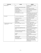
... . Replace compressor. If knocking sounds continue when running , determine the cause. It must be loose. Clean dust or dirt on overload protector. (OLP) CAUSE Fan Loose foreign material inside the housing. Check compressor, replace compressor Check OLP, if externally mounted. Loose set screws Worn bearings of Motor Assembly The bucket is high, remove the OLP, cool, and retest.) -21- Check connection and repair. Replace if open. (If the compressor temperature is not installed...
... . Replace compressor. If knocking sounds continue when running , determine the cause. It must be loose. Clean dust or dirt on overload protector. (OLP) CAUSE Fan Loose foreign material inside the housing. Check compressor, replace compressor Check OLP, if externally mounted. Loose set screws Worn bearings of Motor Assembly The bucket is high, remove the OLP, cool, and retest.) -21- Check connection and repair. Replace if open. (If the compressor temperature is not installed...
Service Manual
Page 28
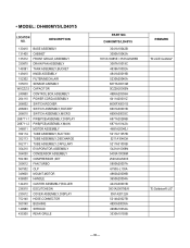
...752140 550140 149980 435300 BASE ASSEMBLY CABINET FRONT GRILLE,ASSEMBLY DRAIN PAN ASSEMBLY TANK ASSEMBLY,BUCKET KNOB ASSEMBLY FILTER(MECH),AIR SENSOR ASEMBLY CONTROL BOX,ASSEMBLY POWER CORD,ASSEMBLY SWITCH,ROCKER SWITCH ASSEMBLY,ROTARY SWITCH ASSEMBLY,MICRO PWB(PCB)ASSEMBLY,DISPLAY PWB(PCB)ASSEMBLY,MAIN MOTOR ASSEMBLY TUBE ASSEMBLY,SUCTION TUBE ASSEMBLY,DISCHARGE TUBE ASSEMBLY,CAPILLARY EVAPORATOR,ASSEMBLY CONDENSOR ASSEMBLY CAPACITOR COMPRESSOR ,SET FAN,TURBO OLP MOUNT,MOTOR HANDLE CASTER ASSEMBLY,ROLLER ESCUTCHEON COVER ASSEMBLY,DISPLAY HOSE,CONNECTOR BUSHING SHROUD REAR GRILLE 3041A10042A...
...752140 550140 149980 435300 BASE ASSEMBLY CABINET FRONT GRILLE,ASSEMBLY DRAIN PAN ASSEMBLY TANK ASSEMBLY,BUCKET KNOB ASSEMBLY FILTER(MECH),AIR SENSOR ASEMBLY CONTROL BOX,ASSEMBLY POWER CORD,ASSEMBLY SWITCH,ROCKER SWITCH ASSEMBLY,ROTARY SWITCH ASSEMBLY,MICRO PWB(PCB)ASSEMBLY,DISPLAY PWB(PCB)ASSEMBLY,MAIN MOTOR ASSEMBLY TUBE ASSEMBLY,SUCTION TUBE ASSEMBLY,DISCHARGE TUBE ASSEMBLY,CAPILLARY EVAPORATOR,ASSEMBLY CONDENSOR ASSEMBLY CAPACITOR COMPRESSOR ,SET FAN,TURBO OLP MOUNT,MOTOR HANDLE CASTER ASSEMBLY,ROLLER ESCUTCHEON COVER ASSEMBLY,DISPLAY HOSE,CONNECTOR BUSHING SHROUD REAR GRILLE 3041A10042A...
Service Manual
Page 29
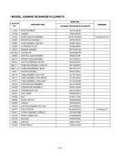
...752140 550140 149980 435300 BASE ASSEMBLY CABINET FRONT GRILLE,ASSEMBLY DRAIN PAN ASSEMBLY TANK ASSEMBLY,BUCKET FILTER(MECH),AIR SENSOR ASEMBLY CONTROL BOX,ASSEMBLY POWER CORD,ASSEMBLY SWITCH ASSEMBLY,MICRO PWB(PCB)ASSEMBLY,DISPLAY PWB(PCB)ASSEMBLY,MAIN MOTOR ASSEMBLY TUBE ASSEMBLY,SUCTION TUBE ASSEMBLY,DISCHARGE TUBE ASSEMBLY,CAPILLARY EVAPORATOR,ASSEMBLY CONDENSOR ASSEMBLY DRIER ASSEMBLY COMPRESSOR ,SET FAN,TURBO OLP MOUNT,MOTOR CAPACITOR HANDLE CASTER ASSEMBLY,ROLLER ESCUTCHEON COVER ASSEMBLY,DISPLAY HOSE,CONNECTOR BUSHING SHROUD REAR GRILLE PART NO. • MODEL: DH300EY5 LOCATION NO.
...752140 550140 149980 435300 BASE ASSEMBLY CABINET FRONT GRILLE,ASSEMBLY DRAIN PAN ASSEMBLY TANK ASSEMBLY,BUCKET FILTER(MECH),AIR SENSOR ASEMBLY CONTROL BOX,ASSEMBLY POWER CORD,ASSEMBLY SWITCH ASSEMBLY,MICRO PWB(PCB)ASSEMBLY,DISPLAY PWB(PCB)ASSEMBLY,MAIN MOTOR ASSEMBLY TUBE ASSEMBLY,SUCTION TUBE ASSEMBLY,DISCHARGE TUBE ASSEMBLY,CAPILLARY EVAPORATOR,ASSEMBLY CONDENSOR ASSEMBLY DRIER ASSEMBLY COMPRESSOR ,SET FAN,TURBO OLP MOUNT,MOTOR CAPACITOR HANDLE CASTER ASSEMBLY,ROLLER ESCUTCHEON COVER ASSEMBLY,DISPLAY HOSE,CONNECTOR BUSHING SHROUD REAR GRILLE PART NO. • MODEL: DH300EY5 LOCATION NO.
Service Manual
Page 30
... 149980 435300 BASE ASSEMBLY CABINET FRONT GRILLE,ASSEMBLY DRAIN PAN ASSEMBLY TANK ASSEMBLY,BUCKET KNOB ASSEMBLY FILTER(MECH),AIR SENSOR ASEMBLY CAPACITOR CONTROL BOX,ASSEMBLY POWER CORD,ASSEMBLY SWITCH,ROCKER SWITCH ASSEMBLY,ROTARY SWITCH ASSEMBLY,MICRO PWB(PCB)ASSEMBLY,DISPLAY PWB(PCB)ASSEMBLY,MAIN MOTOR ASSEMBLY TUBE ASSEMBLY,SUCTION TUBE ASSEMBLY,DISCHARGE TUBE ASSEMBLY,CAPILLARY EVAPORATOR,ASSEMBLY CONDENSOR ASSEMBLY COMPRESSOR ,SET FAN,TURBO OLP MOUNT,MOTOR HANDLE CASTER ASSEMBLY,ROLLER ESCUTCHEON COVER ASSEMBLY,DISPLAY HOSE,CONNECTOR BUSHING SHROUD REAR GRILLE PART NO. DH400MY5/LD40Y5...
... 149980 435300 BASE ASSEMBLY CABINET FRONT GRILLE,ASSEMBLY DRAIN PAN ASSEMBLY TANK ASSEMBLY,BUCKET KNOB ASSEMBLY FILTER(MECH),AIR SENSOR ASEMBLY CAPACITOR CONTROL BOX,ASSEMBLY POWER CORD,ASSEMBLY SWITCH,ROCKER SWITCH ASSEMBLY,ROTARY SWITCH ASSEMBLY,MICRO PWB(PCB)ASSEMBLY,DISPLAY PWB(PCB)ASSEMBLY,MAIN MOTOR ASSEMBLY TUBE ASSEMBLY,SUCTION TUBE ASSEMBLY,DISCHARGE TUBE ASSEMBLY,CAPILLARY EVAPORATOR,ASSEMBLY CONDENSOR ASSEMBLY COMPRESSOR ,SET FAN,TURBO OLP MOUNT,MOTOR HANDLE CASTER ASSEMBLY,ROLLER ESCUTCHEON COVER ASSEMBLY,DISPLAY HOSE,CONNECTOR BUSHING SHROUD REAR GRILLE PART NO. DH400MY5/LD40Y5...
Service Manual
Page 31
... 149980 435300 BASE ASSEMBLY CABINET FRONT GRILLE,ASSEMBLY DRAIN PAN ASSEMBLY TANK ASSEMBLY,BUCKET FILTER(MECH),AIR SENSOR ASEMBLY CAPACITOR CONTROL BOX,ASSEMBLY POWER CORD,ASSEMBLY SWITCH ASSEMBLY,MICRO PWB(PCB)ASSEMBLY,DISPLAY PWB(PCB)ASSEMBLY,MAIN MOTOR ASSEMBLY TUBE ASSEMBLY,SUCTION TUBE ASSEMBLY,DISCHARGE TUBE ASSEMBLY,CAPILLARY EVAPORATOR,ASSEMBLY CONDENSOR ASSEMBLY COMPRESSOR ,SET FAN,TURBO OLP MOUNT,MOTOR HANDLE CASTER ASSEMBLY,ROLLER ESCUTCHEON COVER ASSEMBLY,DISPLAY HOSE,CONNECTOR BUSHING SHROUD REAR GRILLE PART NO. DH404EY5/DH400EY5/LD40EY5 3041A10042B 3090A10042A 3531A10254A...
... 149980 435300 BASE ASSEMBLY CABINET FRONT GRILLE,ASSEMBLY DRAIN PAN ASSEMBLY TANK ASSEMBLY,BUCKET FILTER(MECH),AIR SENSOR ASEMBLY CAPACITOR CONTROL BOX,ASSEMBLY POWER CORD,ASSEMBLY SWITCH ASSEMBLY,MICRO PWB(PCB)ASSEMBLY,DISPLAY PWB(PCB)ASSEMBLY,MAIN MOTOR ASSEMBLY TUBE ASSEMBLY,SUCTION TUBE ASSEMBLY,DISCHARGE TUBE ASSEMBLY,CAPILLARY EVAPORATOR,ASSEMBLY CONDENSOR ASSEMBLY COMPRESSOR ,SET FAN,TURBO OLP MOUNT,MOTOR HANDLE CASTER ASSEMBLY,ROLLER ESCUTCHEON COVER ASSEMBLY,DISPLAY HOSE,CONNECTOR BUSHING SHROUD REAR GRILLE PART NO. DH404EY5/DH400EY5/LD40EY5 3041A10042B 3090A10042A 3531A10254A...
Service Manual
Page 32
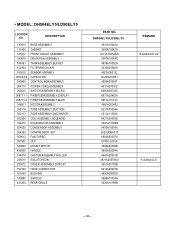
... 554030 554160 359012 567502 349600 436500 144410 238310 235512 752140 550140 149980 435300 BASE ASSEMBLY CABINET FRONT GRILLE,ASSEMBLY DRAIN PAN ASSEMBLY TANK ASSEMBLY,BUCKET FILTER(MECH),AIR SENSOR ASEMBLY CAPACITOR CONTROL BOX,ASSEMBLY POWER CORD,ASSEMBLY SWITCH ASSEMBLY,MICRO PWB(PCB)ASSEMBLY,DISPLAY PWB(PCB)ASSEMBLY,MAIN MOTOR ASSEMBLY TUBE ASSEMBLY,SUCTION TUBE ASSEMBLY,DISCHARGE COIL ASSEMBLY,SOLENOID EVAPORATOR,ASSEMBLY CONDENSOR ASSEMBLY COMPRESSOR ,SET FAN,TURBO OLP MOUNT,MOTOR HANDLE CASTER ASSEMBLY,ROLLER ESCUTCHEON COVER ASSEMBLY,DISPLAY HOSE,CONNECTOR BUSHING SHROUD REAR GRILLE...
... 554030 554160 359012 567502 349600 436500 144410 238310 235512 752140 550140 149980 435300 BASE ASSEMBLY CABINET FRONT GRILLE,ASSEMBLY DRAIN PAN ASSEMBLY TANK ASSEMBLY,BUCKET FILTER(MECH),AIR SENSOR ASEMBLY CAPACITOR CONTROL BOX,ASSEMBLY POWER CORD,ASSEMBLY SWITCH ASSEMBLY,MICRO PWB(PCB)ASSEMBLY,DISPLAY PWB(PCB)ASSEMBLY,MAIN MOTOR ASSEMBLY TUBE ASSEMBLY,SUCTION TUBE ASSEMBLY,DISCHARGE COIL ASSEMBLY,SOLENOID EVAPORATOR,ASSEMBLY CONDENSOR ASSEMBLY COMPRESSOR ,SET FAN,TURBO OLP MOUNT,MOTOR HANDLE CASTER ASSEMBLY,ROLLER ESCUTCHEON COVER ASSEMBLY,DISPLAY HOSE,CONNECTOR BUSHING SHROUD REAR GRILLE...
Service Manual
Page 33
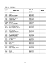
... 752140 550140 149980 435300 BASE ASSEMBLY CABINET FRONT GRILLE,ASSEMBLY DRAIN PAN ASSEMBLY TANK ASSEMBLY,BUCKET FILTER(MECH),AIR SENSOR ASEMBLY CAPACITOR CONTROL BOX,ASSEMBLY POWER CORD,ASSEMBLY SWITCH ASSEMBLY,MICRO PWB(PCB)ASSEMBLY,DISPLAY PWB(PCB)ASSEMBLY,MAIN MOTOR ASSEMBLY TUBE ASSEMBLY,SUCTION TUBE ASSEMBLY,DISCHARGE COIL ASSEMBLY,SOLENOID EVAPORATOR,ASSEMBLY CONDENSOR ASSEMBLY COMPRESSOR ,SET FAN,TURBO OLP MOUNT,MOTOR HANDLE CASTER ASSEMBLY,ROLLER ESCUTCHEON COVER ASSEMBLY,DISPLAY HOSE,CONNECTOR BUSHING SHROUD REAR GRILLE PART NO. LD65ELY5 3041A10042A 3090A10042A 3531A10254E...
... 752140 550140 149980 435300 BASE ASSEMBLY CABINET FRONT GRILLE,ASSEMBLY DRAIN PAN ASSEMBLY TANK ASSEMBLY,BUCKET FILTER(MECH),AIR SENSOR ASEMBLY CAPACITOR CONTROL BOX,ASSEMBLY POWER CORD,ASSEMBLY SWITCH ASSEMBLY,MICRO PWB(PCB)ASSEMBLY,DISPLAY PWB(PCB)ASSEMBLY,MAIN MOTOR ASSEMBLY TUBE ASSEMBLY,SUCTION TUBE ASSEMBLY,DISCHARGE COIL ASSEMBLY,SOLENOID EVAPORATOR,ASSEMBLY CONDENSOR ASSEMBLY COMPRESSOR ,SET FAN,TURBO OLP MOUNT,MOTOR HANDLE CASTER ASSEMBLY,ROLLER ESCUTCHEON COVER ASSEMBLY,DISPLAY HOSE,CONNECTOR BUSHING SHROUD REAR GRILLE PART NO. LD65ELY5 3041A10042A 3090A10042A 3531A10254E...


