Service Manual
Page 1
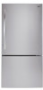
REFRIGERATOR SERVICE MANUAL CAUTION BEFORE SERVICING THE UNIT, READ THE SAFETY PRECAUTIONS IN THIS MANUAL. MODELS: LDC24370ST /00 LDC24370SW /00 LBC24360ST / 00 LBC24360SW /00
REFRIGERATOR SERVICE MANUAL CAUTION BEFORE SERVICING THE UNIT, READ THE SAFETY PRECAUTIONS IN THIS MANUAL. MODELS: LDC24370ST /00 LDC24370SW /00 LBC24360ST / 00 LBC24360SW /00
Service Manual
Page 2
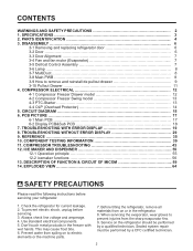
... CFC certified technician. 2 When servicing the evaporator, wear gloves to prevent injuries from spiling on the refrigerator should be performed by a qualified technician. COMPONENT TESTING INFORMATION 39 11. Service on to remove and reinstall... 4-3 PTC-Starter 13 4-4 OLP (Overload Protector 14 5. TROUBLESHOOTING WITHOUT ERROR DISPLAY 29 9. Use standard electrical components. 5. DISASSEMBLY 6 3-1 Removing and replacing refrigerator door 6 3-2 Door ...6 3-3 Door Alignment 7 3-4 Fan and fan motor (Evaporator 7 3-5 Defrost Control Assembly 7 3-6 Lamp 8 3-7 MultiDuct 8 ...
... CFC certified technician. 2 When servicing the evaporator, wear gloves to prevent injuries from spiling on the refrigerator should be performed by a qualified technician. COMPONENT TESTING INFORMATION 39 11. Service on to remove and reinstall... 4-3 PTC-Starter 13 4-4 OLP (Overload Protector 14 5. TROUBLESHOOTING WITHOUT ERROR DISPLAY 29 9. Use standard electrical components. 5. DISASSEMBLY 6 3-1 Removing and replacing refrigerator door 6 3-2 Door ...6 3-3 Door Alignment 7 3-4 Fan and fan motor (Evaporator 7 3-5 Defrost Control Assembly 7 3-6 Lamp 8 3-7 MultiDuct 8 ...
Service Manual
Page 3
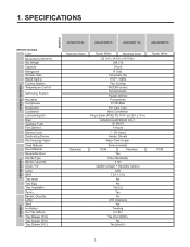
1. SPECIFICATIONS GENERAL FEATURES MODELS FREEZER REFRIGERATOR SPECIFICATIONS Color Dimensions (W*D*H) Net Weight Capacity Refrigerant Climate class Rated Rating Cooling System Temperature Control Defrosting System Insulation Compressor Evaporator Condenser Lubricanting...Tray Vegetable Pantry Basket, Quantity Lamp Shelf Ice Maker Ice Tray & Bank Tray Drawer (F/U) Tray Drawer (F/C) Tray Drawer (F/L) LDC24370ST /00 LDC24370SW /00 LBC24360ST / 00 LBC24360SW /00 Stainless Steel Stainless Super White Stainless Steel (32 3/4 x 34 7/8 x 69 7/8)in 248.5 lb 24cuft R134a Temperate (N) ...
1. SPECIFICATIONS GENERAL FEATURES MODELS FREEZER REFRIGERATOR SPECIFICATIONS Color Dimensions (W*D*H) Net Weight Capacity Refrigerant Climate class Rated Rating Cooling System Temperature Control Defrosting System Insulation Compressor Evaporator Condenser Lubricanting...Tray Vegetable Pantry Basket, Quantity Lamp Shelf Ice Maker Ice Tray & Bank Tray Drawer (F/U) Tray Drawer (F/C) Tray Drawer (F/L) LDC24370ST /00 LDC24370SW /00 LBC24360ST / 00 LBC24360SW /00 Stainless Steel Stainless Super White Stainless Steel (32 3/4 x 34 7/8 x 69 7/8)in 248.5 lb 24cuft R134a Temperate (N) ...
Service Manual
Page 4
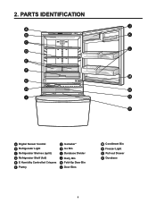
PARTS IDENTIFICATION J A B K C L D E F M G H N I O P A Digital Sensor Control B Refrigerator Light C Refrigerator Shelves (split) D Refrigerator Shelf (full) E E Humidity Controlled Crispers F Pantry G Icemaker* H Ice Bin I Durabase Divider J Dairy Bin K Fold-Up Door Bin L Door Bins M Condiment Bin N Freezer Light O Pull out Drawer P Durabase 4 2.
PARTS IDENTIFICATION J A B K C L D E F M G H N I O P A Digital Sensor Control B Refrigerator Light C Refrigerator Shelves (split) D Refrigerator Shelf (full) E E Humidity Controlled Crispers F Pantry G Icemaker* H Ice Bin I Durabase Divider J Dairy Bin K Fold-Up Door Bin L Door Bins M Condiment Bin N Freezer Light O Pull out Drawer P Durabase 4 2.
Service Manual
Page 6
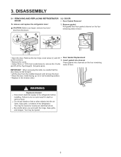
... the reverse order. You may be injured or receive an electrical shock. DISASSEMBLY 3-1 REMOVING AND REPLACING REFRIGERATOR 3-2 DOOR DOOR ● Door Gasket Removal To remove and replace the refrigerator door: CAUTION: Before you work with the hinge, base grille, and stopper. Insert gasket into the... air vents, base grille, or bottom of the refrigerator. Set parts aside. Failure to the refrigerator before installing. Be careful when you begin, remove food and bins from the doors. 1. Remove gasket Pull gasket free...
... the reverse order. You may be injured or receive an electrical shock. DISASSEMBLY 3-1 REMOVING AND REPLACING REFRIGERATOR 3-2 DOOR DOOR ● Door Gasket Removal To remove and replace the refrigerator door: CAUTION: Before you work with the hinge, base grille, and stopper. Insert gasket into the... air vents, base grille, or bottom of the refrigerator. Set parts aside. Failure to the refrigerator before installing. Be careful when you begin, remove food and bins from the doors. 1. Remove gasket Pull gasket free...
Service Manual
Page 7
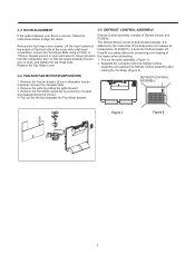
... your doors is uneven, follow the instructions below to defrost automatically. At 46F(8°C), it turns the Defrost Heater off. hold the refrigerator door so that the space between your refrigerator has an icemaker, remove the icemaker first). 2. Loosen the Top Hinge Bolts using a 10mm or Fuse-M is Remove the top hinge...
... your doors is uneven, follow the instructions below to defrost automatically. At 46F(8°C), it turns the Defrost Heater off. hold the refrigerator door so that the space between your refrigerator has an icemaker, remove the icemaker first). 2. Loosen the Top Hinge Bolts using a 10mm or Fuse-M is Remove the top hinge...

Service Manual
Page 8
... cover 3) Disconnect wire harness and replace the main PWB in the reverse order of refrigerator light. 3-7 MULTI DUCT 1. 3-6 LAMP Unplug Refrigerator, or disconnect power at the circuit breaker. If necessary, remove top shelf or shelves. 3-6-1 Refrigerator Compartment Lamp 1) Unplug refrigerator power cord from connector. 4) Replace the LED assembly. 3-8 MAIN PWB 1) Loosen 3 screws on the...
... cover 3) Disconnect wire harness and replace the main PWB in the reverse order of refrigerator light. 3-7 MULTI DUCT 1. 3-6 LAMP Unplug Refrigerator, or disconnect power at the circuit breaker. If necessary, remove top shelf or shelves. 3-6-1 Refrigerator Compartment Lamp 1) Unplug refrigerator power cord from connector. 4) Replace the LED assembly. 3-8 MAIN PWB 1) Loosen 3 screws on the...
Service Manual
Page 12
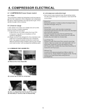
Parts may fail due to breakdown of the refrigerator and compresses this gas to high-temperature and high-pressure gas. COMPRESSOR ELECTRICAL 4-1 COMPRESSOR (Freezer Drawer model) 4-1-1 Role The compressor intakes low temperature and low ...
Parts may fail due to breakdown of the refrigerator and compresses this gas to high-temperature and high-pressure gas. COMPRESSOR ELECTRICAL 4-1 COMPRESSOR (Freezer Drawer model) 4-1-1 Role The compressor intakes low temperature and low ...
Service Manual
Page 13
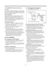
... and moisture-free environment, use extreme caution when repairing it must be careful that dust, humidity, and soldering flux don't contaminate the inside of the refrigerator and compresses this gas to the condenser. 4-2-2 Composition The compressor includes overload protection. Durign the starting device which uses ceramic material consisting of the Hermetic...
... and moisture-free environment, use extreme caution when repairing it must be careful that dust, humidity, and soldering flux don't contaminate the inside of the refrigerator and compresses this gas to the condenser. 4-2-2 Composition The compressor includes overload protection. Durign the starting device which uses ceramic material consisting of the Hermetic...
Service Manual
Page 14
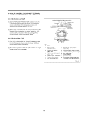
... alloy (To engage 2.33/2.66 mm dia. 4-4 OLP (OVERLOAD PROTECTOR) 4-4-1 Definition of OLP (1) OLP (OVERLOAD PROTECTOR) is attached to the Sealed Compressor used for the Refrigerator. Name Base, phenolic (UL 94 V-0 rated) Movable arm support, plated steel.
... alloy (To engage 2.33/2.66 mm dia. 4-4 OLP (OVERLOAD PROTECTOR) 4-4-1 Definition of OLP (1) OLP (OVERLOAD PROTECTOR) is attached to the Sealed Compressor used for the Refrigerator. Name Base, phenolic (UL 94 V-0 rated) Movable arm support, plated steel.
Service Manual
Page 19
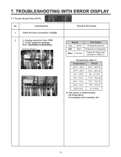
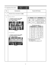
... Error (FS E) No Checking flow 1 Check for loose connection in CON7. Result 0Ω Short OFF Open Other Normal SVC Action Change the sensor Replace the refrigerator Check the Temp and resistance (Table-1) Temperature Result -22°F / -30°C 40.5 ~ 38.5 ㏀ -13°F / -25°C 30.5 ~ 28.5 ㏀ -4°F / -20°...
... Error (FS E) No Checking flow 1 Check for loose connection in CON7. Result 0Ω Short OFF Open Other Normal SVC Action Change the sensor Replace the refrigerator Check the Temp and resistance (Table-1) Temperature Result -22°F / -30°C 40.5 ~ 38.5 ㏀ -13°F / -25°C 30.5 ~ 28.5 ㏀ -4°F / -20°...
Service Manual
Page 20
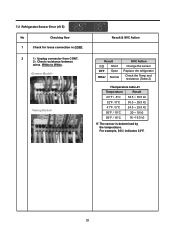
.... For example, 30㏀ indicates 32°F. 20 Result & SVC Action Result 0Ω Short OFF Open Other Normal SVC Action Change the sensor Replace the refrigerator Check the Temp and resistance (Table-2) Temperature Result 23°F / -5°C 38.5 ~ 36.5 ㏀ 32°F / 0°C 30.5 ~ 29.5 ㏀ 41°F /... ~ 19 ㏀ 59°F / 15°C 16 ~15.5 ㏀ ※ The sensor is determined by the temperature. Unplug connector from CON7. 2-. 7-2 Refrigerator Sensor Error (rS E) No Checking flow 1 Check for loose connection in CON7. 2 1-.
.... For example, 30㏀ indicates 32°F. 20 Result & SVC Action Result 0Ω Short OFF Open Other Normal SVC Action Change the sensor Replace the refrigerator Check the Temp and resistance (Table-2) Temperature Result 23°F / -5°C 38.5 ~ 36.5 ㏀ 32°F / 0°C 30.5 ~ 29.5 ㏀ 41°F /... ~ 19 ㏀ 59°F / 15°C 16 ~15.5 ㏀ ※ The sensor is determined by the temperature. Unplug connector from CON7. 2-. 7-2 Refrigerator Sensor Error (rS E) No Checking flow 1 Check for loose connection in CON7. 2 1-.
Service Manual
Page 21
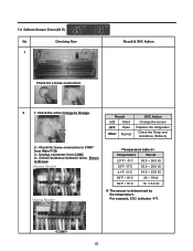
... CON8. 2-. For example, 23㏀ indicates -4°F. 21 Result & SVC Action Result 0Ω Short OFF Open Other Normal SVC Action Change the sensor Replace the refrigerator Check the Temp and resistance (Table-1) Temperature Result -22°F / -30°C 40.5 ~ 38.5 ㏀ -13°F / -25°C 30.5 ~ 28.5 ㏀ -4°F / -20°...
... CON8. 2-. For example, 23㏀ indicates -4°F. 21 Result & SVC Action Result 0Ω Short OFF Open Other Normal SVC Action Change the sensor Replace the refrigerator Check the Temp and resistance (Table-1) Temperature Result -22°F / -30°C 40.5 ~ 38.5 ㏀ -13°F / -25°C 30.5 ~ 28.5 ㏀ -4°F / -20°...
Service Manual
Page 22
Result 0Ω Short OFF Open Other Normal SVC Action Change the sensor Replace the refrigerator Check the Temp and resistance (Table-3) 2.- Temperature Result 23°F / -5°C 38.5 ~ 36.5 ㏀ 32°F / 0°C 30.5 ~ 29.5 ㏀ 41°F / 5°C 24.5 ~ 23.5 &#...
Result 0Ω Short OFF Open Other Normal SVC Action Change the sensor Replace the refrigerator Check the Temp and resistance (Table-3) 2.- Temperature Result 23°F / -5°C 38.5 ~ 36.5 ㏀ 32°F / 0°C 30.5 ~ 29.5 ㏀ 41°F / 5°C 24.5 ~ 23.5 &#...
Service Manual
Page 30
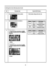
... between wires Black to Gray/Red . Check for loose connection in CON5. 2-. Check voltage between wires Black to Orange. 30 8-2 Refrigerator room LED Lamp doesn't work No Checking flow 1 Check the Refrigerator door switch. Status Normal Push S/W Result 0 Other Infinity Other SVC Action Go to the 3 Change door Switch Go to the...
... between wires Black to Gray/Red . Check for loose connection in CON5. 2-. Check voltage between wires Black to Orange. 30 8-2 Refrigerator room LED Lamp doesn't work No Checking flow 1 Check the Refrigerator door switch. Status Normal Push S/W Result 0 Other Infinity Other SVC Action Go to the 3 Change door Switch Go to the...
Service Manual
Page 31
Check for loose connection in Refrigerator LED Lamp connector. 2-. Check voltage between wires White to customer Change the LED Lamp 31 Result & SVC Action Status Closed Open Result 0 ~ 2 V Other 12 V Other SVC Action Explain to customer Change the Door S/W Explain to Gray. 8-2 Refrigerator room lamp doesn't work No Checking flow 4 1.-
Check for loose connection in Refrigerator LED Lamp connector. 2-. Check voltage between wires White to customer Change the LED Lamp 31 Result & SVC Action Status Closed Open Result 0 ~ 2 V Other 12 V Other SVC Action Explain to customer Change the Door S/W Explain to Gray. 8-2 Refrigerator room lamp doesn't work No Checking flow 4 1.-
Service Manual
Page 35
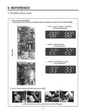
REFERENCE 9-1 TEST MODE and Removing TPA 1. How to remove Terminal Position Assurance (TPA) After measure the values, you push the test button on the Main PCB, the refrigerator will be enter the TEST MODE. * 1 time : Comp / Damper / All FAN on (All things displayed) Main PCB * 2 times : Damper closed (22 22 displayed) * 3 times : Forced defrost mode (33 33 displayed) 2. 9. How to make TEST MODE If you should put in the TPA again. 35
REFERENCE 9-1 TEST MODE and Removing TPA 1. How to remove Terminal Position Assurance (TPA) After measure the values, you push the test button on the Main PCB, the refrigerator will be enter the TEST MODE. * 1 time : Comp / Damper / All FAN on (All things displayed) Main PCB * 2 times : Damper closed (22 22 displayed) * 3 times : Forced defrost mode (33 33 displayed) 2. 9. How to make TEST MODE If you should put in the TPA again. 35
Service Manual
Page 41
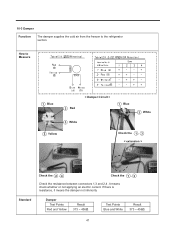
If there is resistance, it means the damper not inferiority Standard Damper Test Points Red and Yellow Result 373 ~ 456Ω Test Points Blue and White Result 373 ~ 456Ω 41 10-3 Damper Function The damper supplies the cold air from the freezer to Measure 1 Blue 2 Red < Damper Circuit > 1 Blue 3 White 3 White 3 Yellow Check the 1 , 3 < extension > Check the 2 , 4 Check the 1 , 3 Check the resistance between connectors 1,3 and 2,4 .It means check whether or not applying an electric current. How to the refrigerator section.
If there is resistance, it means the damper not inferiority Standard Damper Test Points Red and Yellow Result 373 ~ 456Ω Test Points Blue and White Result 373 ~ 456Ω 41 10-3 Damper Function The damper supplies the cold air from the freezer to Measure 1 Blue 2 Red < Damper Circuit > 1 Blue 3 White 3 White 3 Yellow Check the 1 , 3 < extension > Check the 2 , 4 Check the 1 , 3 Check the resistance between connectors 1,3 and 2,4 .It means check whether or not applying an electric current. How to the refrigerator section.
Service Manual
Page 42
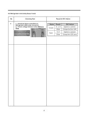
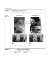
When the door open , internal contact operate on . - If there is resistance, it means the switch not inferiority Multimeter beep - Button (Plunger) 12 34 1 2 34 34 21 Standard Beep Beep Check the resistance between connectors 1, 2 and 3, 4 .It means check whether or not applying an electric current. When the door open , the switch give information to Measure The switch sense if the door open , light on and off moving plunger of door switch up and down. Switch F,R Nomal Push the button(Plunger) Beep or 0Ω None (∞Ω) 42 When the door open or ...
When the door open , internal contact operate on . - If there is resistance, it means the switch not inferiority Multimeter beep - Button (Plunger) 12 34 1 2 34 34 21 Standard Beep Beep Check the resistance between connectors 1, 2 and 3, 4 .It means check whether or not applying an electric current. When the door open , the switch give information to Measure The switch sense if the door open , light on and off moving plunger of door switch up and down. Switch F,R Nomal Push the button(Plunger) Beep or 0Ω None (∞Ω) 42 When the door open or ...

Service Manual
Page 43
N Check? N Recheck Reset LED blink2 Comp. N Check? Y Y N Heavy Repair Leakage? N Work? Y Y Refrigerant N leak ? 43 IPM output > 80V-20% Y Recheck N Replace Driver PCB Comp. Heavy Repair Y Y Leakage? N Work? N Work? N LED blink 1 LED ... 1 LED blink 7 Comp. N Replace Driver PCB Replace Driver PCB Reset LED blink 5 Comp. Replace Comp. Y N Fix Harness Heavy Repair Y Refrigerant N leak? Reset LED blink6 Comp. COMPRESSOR TROUBLESHOOTING PCB Check (Simplify) A-inverter Power Off Con201 Disconnect Test Button TEST 1 Mode Protection Logic Power On ...
N Check? N Recheck Reset LED blink2 Comp. N Check? Y Y N Heavy Repair Leakage? N Work? Y Y Refrigerant N leak ? 43 IPM output > 80V-20% Y Recheck N Replace Driver PCB Comp. Heavy Repair Y Y Leakage? N Work? N Work? N LED blink 1 LED ... 1 LED blink 7 Comp. N Replace Driver PCB Replace Driver PCB Reset LED blink 5 Comp. Replace Comp. Y N Fix Harness Heavy Repair Y Refrigerant N leak? Reset LED blink6 Comp. COMPRESSOR TROUBLESHOOTING PCB Check (Simplify) A-inverter Power Off Con201 Disconnect Test Button TEST 1 Mode Protection Logic Power On ...


