Service Manual
Page 2
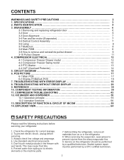
... 9. SPECIFICATIONS 3 2. DISASSEMBLY 6 3-1 Removing and replacing refrigerator door 6 3-2 Door ...6 3-3 Door Alignment 7 3-4 Fan and fan motor (Evaporator 7 3-5 Defrost Control Assembly 7 3-6 Lamp 8 3-7 MultiDuct 8 3-8 Main PWB 8 3-9 How to prevent injuries from on or in the freezer with wet hands. COMPRESSOR ELECTRICAL 12 4-1 Compressor Freezer Drawer model 12 4-2 Compressor Freezer Swing model 13 4-3 PTC-Starter 13 4-4 OLP (Overload Protector 14 5. COMPRESSOR TROUBLESHOOTING 43 12. EXPLODED VIEW 64 SAFETY PRECAUTIONS Please read the following instructions before...
... 9. SPECIFICATIONS 3 2. DISASSEMBLY 6 3-1 Removing and replacing refrigerator door 6 3-2 Door ...6 3-3 Door Alignment 7 3-4 Fan and fan motor (Evaporator 7 3-5 Defrost Control Assembly 7 3-6 Lamp 8 3-7 MultiDuct 8 3-8 Main PWB 8 3-9 How to prevent injuries from on or in the freezer with wet hands. COMPRESSOR ELECTRICAL 12 4-1 Compressor Freezer Drawer model 12 4-2 Compressor Freezer Swing model 13 4-3 PTC-Starter 13 4-4 OLP (Overload Protector 14 5. COMPRESSOR TROUBLESHOOTING 43 12. EXPLODED VIEW 64 SAFETY PRECAUTIONS Please read the following instructions before...
Service Manual
Page 3
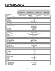
1. SPECIFICATIONS GENERAL FEATURES MODELS FREEZER REFRIGERATOR SPECIFICATIONS Color Dimensions (W*D*H) Net Weight Capacity Refrigerant Climate class Rated Rating Cooling System Temperature Control Defrosting System Insulation Compressor Evaporator Condenser Lubricanting Oil Drier Capillary Tube First Defrost Defrost Cycle Desfrosting Device Anti-freezing Heater Case Material Door Material Reversible Door Handle Type Basket, Quantity Cover, T/V Lamp Shelf Tray meat Tray Egg Tray Vegetable Pantry Basket, Quantity Lamp Shelf Ice Maker Ice Tray & Bank Tray Drawer (F/U) Tray Drawer (F/C) Tray ...
1. SPECIFICATIONS GENERAL FEATURES MODELS FREEZER REFRIGERATOR SPECIFICATIONS Color Dimensions (W*D*H) Net Weight Capacity Refrigerant Climate class Rated Rating Cooling System Temperature Control Defrosting System Insulation Compressor Evaporator Condenser Lubricanting Oil Drier Capillary Tube First Defrost Defrost Cycle Desfrosting Device Anti-freezing Heater Case Material Door Material Reversible Door Handle Type Basket, Quantity Cover, T/V Lamp Shelf Tray meat Tray Egg Tray Vegetable Pantry Basket, Quantity Lamp Shelf Ice Maker Ice Tray & Bank Tray Drawer (F/U) Tray Drawer (F/C) Tray ...
Service Manual
Page 6
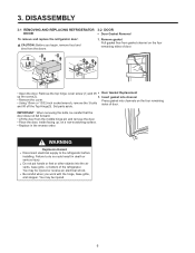
...; Open the door. Insert gasket into the air vents, base grille, or bottom of door. 3. Remove gasket Pull gasket free from the doors. 1. IMPORTANT : When removing the bolts, be careful that the door does not fall forward. • Lift the door from the middle hinge pin and remove the door. • Place the door, inside facing up the cover(2). 1. Set parts aside. Failure to the refrigerator before installing. Be careful when you begin, remove food and bins...
...; Open the door. Insert gasket into the air vents, base grille, or bottom of door. 3. Remove gasket Pull gasket free from the doors. 1. IMPORTANT : When removing the bolts, be careful that the door does not fall forward. • Lift the door from the middle hinge pin and remove the door. • Place the door, inside facing up the cover(2). 1. Set parts aside. Failure to the refrigerator before installing. Be careful when you begin, remove food and bins...
Service Manual
Page 7
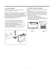
... of the cover with the Defrost Control assembly and replace the Defrost Control assembly after cutting the Tie Wrap. (Figure 2) 3-4 FAN AND FAN MOTOR(EVAPORATOR) 1. hold the refrigerator door so that the space between your refrigerator has an icemaker, remove the icemaker first). 2. Pull out the grille assembly. (Figure 1) 2. Pull out the fan and separate the Fan Motor bracket. It is uneven, follow the instructions below to defrost automatically. Loosen the Top Hinge Bolts using a 10mm...
... of the cover with the Defrost Control assembly and replace the Defrost Control assembly after cutting the Tie Wrap. (Figure 2) 3-4 FAN AND FAN MOTOR(EVAPORATOR) 1. hold the refrigerator door so that the space between your refrigerator has an icemaker, remove the icemaker first). 2. Pull out the grille assembly. (Figure 1) 2. Pull out the fan and separate the Fan Motor bracket. It is uneven, follow the instructions below to defrost automatically. Loosen the Top Hinge Bolts using a 10mm...

Service Manual
Page 8
... the reverse order of refrigerator light. 3-7 MULTI DUCT 1. If necessary, remove top shelf or shelves. 3-6-1 Refrigerator Compartment Lamp 1) Unplug refrigerator power cord from connector. 4) Replace the LED assembly. 3-8 MAIN PWB 1) Loosen 3 screws on the bottom position. 3) Remove the LED assembly from electric outlet. 2) Put flat screwdriver into service hole and remove cover of removal. 8 Unplug refrigerator power cord form outlet. 2. 3-6 LAMP Unplug Refrigerator, or disconnect power at the circuit breaker. Remove screw with driver...
... the reverse order of refrigerator light. 3-7 MULTI DUCT 1. If necessary, remove top shelf or shelves. 3-6-1 Refrigerator Compartment Lamp 1) Unplug refrigerator power cord from connector. 4) Replace the LED assembly. 3-8 MAIN PWB 1) Loosen 3 screws on the bottom position. 3) Remove the LED assembly from electric outlet. 2) Put flat screwdriver into service hole and remove cover of removal. 8 Unplug refrigerator power cord form outlet. 2. 3-6 LAMP Unplug Refrigerator, or disconnect power at the circuit breaker. Remove screw with driver...
Service Manual
Page 12
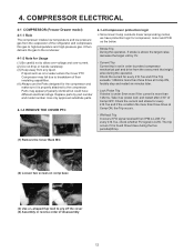
... Stroke Trip During the operation, if stroke is set in reverse order of Comp OFF. For every 416.7us, check whether FO signal is LOW. COMPRESSOR ELECTRICAL 4-1 COMPRESSOR (Freezer Drawer model) 4-1-1 Role The compressor intakes low temperature and low pressure gas from any liquid. Parts may fail due to breakdown of the refrigerator and compresses this gas to high-temperature and high-pressure gas...
... Stroke Trip During the operation, if stroke is set in reverse order of Comp OFF. For every 416.7us, check whether FO signal is LOW. COMPRESSOR ELECTRICAL 4-1 COMPRESSOR (Freezer Drawer model) 4-1-1 Role The compressor intakes low temperature and low pressure gas from any liquid. Parts may fail due to breakdown of the refrigerator and compresses this gas to high-temperature and high-pressure gas...
Service Manual
Page 13
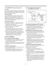
... may cause noise, improper operation or even cause it to restart until the PTC device has cooled. Parts may appear physically identical but could result in damage to the product, fire, injury, or possibly death. 4-3-6 Note for Usage (1) Be careful not to high-temperature and high-pressure gas. Using an incorrect part could have different electrical ratings. Replace parts by part number and model number. It...
... may cause noise, improper operation or even cause it to restart until the PTC device has cooled. Parts may appear physically identical but could result in damage to the product, fire, injury, or possibly death. 4-3-6 Note for Usage (1) Be careful not to high-temperature and high-pressure gas. Using an incorrect part could have different electrical ratings. Replace parts by part number and model number. It...
Service Manual
Page 19
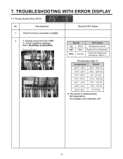
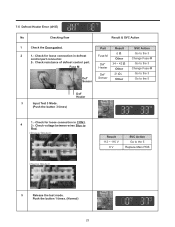
7. Unplug connector from CON7. 2-. Result 0Ω Short OFF Open Other Normal SVC Action Change the sensor Replace the refrigerator Check the Temp and resistance (Table-1) Temperature Result -22°F / -30°C 40.5 ~ 38.5 ㏀ -13°F...㏀ ※ The sensor is determined by the temperature. TROUBLESHOOTING WITH ERROR DISPLAY 7-1 Freezer Sensor Error (FS E) No Checking flow 1 Check for loose connection in CON7. Check resistance between wires Blue/White to Blue/White. Result & SVC Action 2 1-. For example, 23㏀ indicates -4°F. 19
7. Unplug connector from CON7. 2-. Result 0Ω Short OFF Open Other Normal SVC Action Change the sensor Replace the refrigerator Check the Temp and resistance (Table-1) Temperature Result -22°F / -30°C 40.5 ~ 38.5 ㏀ -13°F...㏀ ※ The sensor is determined by the temperature. TROUBLESHOOTING WITH ERROR DISPLAY 7-1 Freezer Sensor Error (FS E) No Checking flow 1 Check for loose connection in CON7. Check resistance between wires Blue/White to Blue/White. Result & SVC Action 2 1-. For example, 23㏀ indicates -4°F. 19
Service Manual
Page 23
7-5 Defrost Heater Error (dH E) No Checking flow Result & SVC Action 1 Check the Door gasket. Part Result SVC Action 2 1.- Fuse-M 0Ω Other Go to the 5 Replace Main PCB 5 Release the test mode. Check for loose connection in CON3. 4 2-. Check resistance of defrost control part. Result 112 ~ 116 V 0 V SVC Action Go to the 3 Change Fuse-M 2-. Fuse M Def' Heater 34 ~ 42 Ω Other Go to the 3 Change Fuse...
7-5 Defrost Heater Error (dH E) No Checking flow Result & SVC Action 1 Check the Door gasket. Part Result SVC Action 2 1.- Fuse-M 0Ω Other Go to the 5 Replace Main PCB 5 Release the test mode. Check for loose connection in CON3. 4 2-. Check resistance of defrost control part. Result 112 ~ 116 V 0 V SVC Action Go to the 3 Change Fuse-M 2-. Fuse M Def' Heater 34 ~ 42 Ω Other Go to the 3 Change Fuse...
Service Manual
Page 25
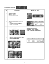
Check for loose connection in CON7. 2-. Check fan motor voltage. Point (2)~(3) (1)~(3) Result Below 7V 0 or 5 V SVC Action Change the PCB Change the motor (3)(2)(1) (3)(2)(1) 25 7-6 Freezer Fan Error (FF E) No Checking flow 1 Reset the unit and Input Test 1 Mode. (Push the button 1 time) Result & SVC Action 2 Open the freezer door and Check the air flow. ※ While an error code is displayed, the fan is not working. 3 Check the Fan motor. Status No windy Windy SVC...
Check for loose connection in CON7. 2-. Check fan motor voltage. Point (2)~(3) (1)~(3) Result Below 7V 0 or 5 V SVC Action Change the PCB Change the motor (3)(2)(1) (3)(2)(1) 25 7-6 Freezer Fan Error (FF E) No Checking flow 1 Reset the unit and Input Test 1 Mode. (Push the button 1 time) Result & SVC Action 2 Open the freezer door and Check the air flow. ※ While an error code is displayed, the fan is not working. 3 Check the Fan motor. Status No windy Windy SVC...

Service Manual
Page 43
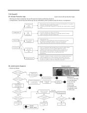
...? COMPRESSOR TROUBLESHOOTING PCB Check (Simplify) A-inverter Power Off Con201 Disconnect Test Button TEST 1 Mode Protection Logic Power On Time>30sec Y PCB OK & V≒200 N Replace Driver PCB Check Voltage about 200V past 30second after turn on Test Mode Ref. Replace Comp. Y N Fix Harness Heavy Repair Y Refrigerant N leak? N Work? Harness Y Check? Y Y N Heavy Repair Leakage? TEST1 Forced Starting Comp FC75(A-Inverter) TDC (Full Stroke) Display & sound Display ON, Buzz 1 time Refer Troubleshooting Not Cooling Recheck Reset LED Y Blink...
...? COMPRESSOR TROUBLESHOOTING PCB Check (Simplify) A-inverter Power Off Con201 Disconnect Test Button TEST 1 Mode Protection Logic Power On Time>30sec Y PCB OK & V≒200 N Replace Driver PCB Check Voltage about 200V past 30second after turn on Test Mode Ref. Replace Comp. Y N Fix Harness Heavy Repair Y Refrigerant N leak? N Work? Harness Y Check? Y Y N Heavy Repair Leakage? TEST1 Forced Starting Comp FC75(A-Inverter) TDC (Full Stroke) Display & sound Display ON, Buzz 1 time Refer Troubleshooting Not Cooling Recheck Reset LED Y Blink...
Service Manual
Page 49
... be activated by other problems then the driver or compressor. We have to slightly higher. of Discharge line and Condenser No Is there frost on compressor is opened, and refrigerant is not expelled because it has accumulated in drip tray No Check Temp of compressor and discharge line is present. Evaporator inlet 7. 11-4 Check D D1. The high side pressure and temperature will flow out...
... be activated by other problems then the driver or compressor. We have to slightly higher. of Discharge line and Condenser No Is there frost on compressor is opened, and refrigerant is not expelled because it has accumulated in drip tray No Check Temp of compressor and discharge line is present. Evaporator inlet 7. 11-4 Check D D1. The high side pressure and temperature will flow out...
Service Manual
Page 51
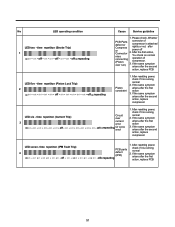
..., replace PCB 51 on - off repeating Or cycle error 1. off - After resetting power, 4 LED seven- off - o-non - Please check, Whether PCB Parts defect or Compress or Connector miss connecting (Piston over 3 current error on - on - on - on - on - on - on -on - on - If the same symptom arises after power off PCB parts defect (IPM) repeating check if it is running...
..., replace PCB 51 on - off repeating Or cycle error 1. off - After resetting power, 4 LED seven- off - o-non - Please check, Whether PCB Parts defect or Compress or Connector miss connecting (Piston over 3 current error on - on - on - on - on - on - on -on - on - If the same symptom arises after power off PCB parts defect (IPM) repeating check if it is running...
Service Manual
Page 52
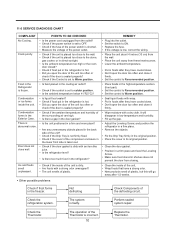
.... • Adjust the Leveling Screw, and position the refrigerator in a firm place. • Remove the objects. • Fix the Drip Tray firmly in the original position. • Place the cover in its original position. • Clean the door gasket. • Position in a firm place and level the Leveling Screw. • Make sure food stored in shelves does not prevent the door from closing. • Clean the inside of...
.... • Adjust the Leveling Screw, and position the refrigerator in a firm place. • Remove the objects. • Fix the Drip Tray firmly in the original position. • Place the cover in its original position. • Clean the door gasket. • Position in a firm place and level the Leveling Screw. • Make sure food stored in shelves does not prevent the door from closing. • Clean the inside of...
Service Manual
Page 53
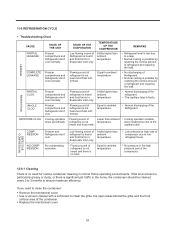
... Freezer and Refrigerator don't cool. Equal to ambient temperature. • Low pressure at high side of compressor due to clean the grille, the open areas behind the grille and the front surface area of the compressor. 12-6-1 Cleaning There is no need to clean the condenser: ● Remove the mechanical cover. ● Use a vacuum cleaner with a soft brush to low refrigerant level. • No pressure in Evaporator...
... Freezer and Refrigerator don't cool. Equal to ambient temperature. • Low pressure at high side of compressor due to clean the grille, the open areas behind the grille and the front surface area of the compressor. 12-6-1 Cleaning There is no need to clean the condenser: ● Remove the mechanical cover. ● Use a vacuum cleaner with a soft brush to low refrigerant level. • No pressure in Evaporator...

Service Manual
Page 55
... after Ice Maker starts operation. • Check ice bucket is full of ice by rotating Feeler Arm motor in normal and reverse direction and eject ice into the ice bucket if ice bucket is not full. • Performs Icemaking Mode after supplying water by operating the SOLENOID in ICE VALVE. • To operate LINE and SERVICE, press and hold the Fill Key for 3 seconds. Feeler Arm 55 Power Switch Turning the Icemaker stop switch off (O) stops the Icemaking...
... after Ice Maker starts operation. • Check ice bucket is full of ice by rotating Feeler Arm motor in normal and reverse direction and eject ice into the ice bucket if ice bucket is not full. • Performs Icemaking Mode after supplying water by operating the SOLENOID in ICE VALVE. • To operate LINE and SERVICE, press and hold the Fill Key for 3 seconds. Feeler Arm 55 Power Switch Turning the Icemaker stop switch off (O) stops the Icemaking...

Service Manual
Page 58
..., change will work only when ice tray its in horizontal position, not during ice ejection or water supplying. POWER SWITCH TEST SWITCH 12-2-5 Water Supply Function This function is for more than 3 seconds. Water supply. Water supply quantity depend of 30 seconds its done. Test switch will be depend of icemaker 12-2-6 Ice maker stop switch • Ice Maker Stop S/W ON state, Ice Maker normal operation • Ice Maker Stop S/W OFF state: Ice Maker do not operate 58 User shouldn't force operation while doing test mode, service or cleaning. If water supply setting is...
..., change will work only when ice tray its in horizontal position, not during ice ejection or water supplying. POWER SWITCH TEST SWITCH 12-2-5 Water Supply Function This function is for more than 3 seconds. Water supply. Water supply quantity depend of 30 seconds its done. Test switch will be depend of icemaker 12-2-6 Ice maker stop switch • Ice Maker Stop S/W ON state, Ice Maker normal operation • Ice Maker Stop S/W OFF state: Ice Maker do not operate 58 User shouldn't force operation while doing test mode, service or cleaning. If water supply setting is...

Service Manual
Page 59
... the ADJUST button. 2. Control range : 33°F ~ 46°F 1°C ~ 8°C Control range : -6°F ~ 8°F -21°C ~ -13°C 13-1-2 How to Change the Temperature Mode to press the ICE PLUS key and the icon will turn ON. Whenever selection switch is opened for the freezer. To protect the risk of this function you need to °F/°C 1. When the power is powered on again, ICE...
... the ADJUST button. 2. Control range : 33°F ~ 46°F 1°C ~ 8°C Control range : -6°F ~ 8°F -21°C ~ -13°C 13-1-2 How to Change the Temperature Mode to press the ICE PLUS key and the icon will turn ON. Whenever selection switch is opened for the freezer. To protect the risk of this function you need to °F/°C 1. When the power is powered on again, ICE...

Service Manual
Page 60
... the door is produced. 13-1-8 Defrosting (removing frost) 1. Freezer Door or Refrigerator Door Closed Open Closed Open Closed 3 Times 3 Times 3 Times 3 Times Buzzer Within 1 min. 1 min. 30 sec 30 sec 30 sec 13-1-7 Buzzer Sound When the button on or for restoring power, defrosting starts when the compressor running time reaches between 7~50 hours and 50 hours according to door open time. 2. Defrosting stops if the sensor temperature reaches...
... the door is produced. 13-1-8 Defrosting (removing frost) 1. Freezer Door or Refrigerator Door Closed Open Closed Open Closed 3 Times 3 Times 3 Times 3 Times Buzzer Within 1 min. 1 min. 30 sec 30 sec 30 sec 13-1-7 Buzzer Sound When the button on or for restoring power, defrosting starts when the compressor running time reaches between 7~50 hours and 50 hours according to door open time. 2. Defrosting stops if the sensor temperature reaches...

Service Manual
Page 62
... E", "It E" error, are displayed. The defect CODE shows on display panel Error Code ① Error Code ② Error Detection Error Display NO Freezer Ref Error Generation Factors Category Temperature Temperature Remark 1 Normality 2 Freezer Sensor Error FS 3 Refrigerator Sensor Error rS 4 Room Temp Sensor Error rt 5 Defrosting Sensor Error dS 6 Icing Sensor Error IS 7 Poor Defrosting dH Error BLDC 8 Motor Operation FF Freezer Fan Error BLDC 9 Motor Operation CF Condenser Fan 10 Ice Maker Kit defect It None E Short or open in Freezer Sensor circuit...
... E", "It E" error, are displayed. The defect CODE shows on display panel Error Code ① Error Code ② Error Detection Error Display NO Freezer Ref Error Generation Factors Category Temperature Temperature Remark 1 Normality 2 Freezer Sensor Error FS 3 Refrigerator Sensor Error rS 4 Room Temp Sensor Error rt 5 Defrosting Sensor Error dS 6 Icing Sensor Error IS 7 Poor Defrosting dH Error BLDC 8 Motor Operation FF Freezer Fan Error BLDC 9 Motor Operation CF Condenser Fan 10 Ice Maker Kit defect It None E Short or open in Freezer Sensor circuit...


