

Service Manual
Page 1
Only for authorized service personnel. http://biz.lgservice.com Window Air Conditioner SVC MANUAL(General) MODEL : Window CAUTION Before Servicing the unit, read the safety precautions in General SVC manual.
Only for authorized service personnel. http://biz.lgservice.com Window Air Conditioner SVC MANUAL(General) MODEL : Window CAUTION Before Servicing the unit, read the safety precautions in General SVC manual.
Service Manual
Page 2
Air Conditioner Service Manual CONTENTS Safety Precautions ...3 Operation ...6 Features ...6 Control Locations Function of Controls 6 Troubleshooting Guide...9 Piping System ...9 Troubleshooting Guide...10 Electrical Parts Troubleshooting Guide 12 Room Air Conditioner Voltage Limits 20 2 Window Air Conditioner
Air Conditioner Service Manual CONTENTS Safety Precautions ...3 Operation ...6 Features ...6 Control Locations Function of Controls 6 Troubleshooting Guide...9 Piping System ...9 Troubleshooting Guide...10 Electrical Parts Troubleshooting Guide 12 Room Air Conditioner Voltage Limits 20 2 Window Air Conditioner

Service Manual
Page 3
Be sure to OFF and remove the POWER SUPPLY cables. 2. INSULATION RESISTANCE TEST 1. Measure the resistance value with it. This voltage is to be open. 3. I Incorrect operation due to the power cables. When servicing the unit, set the main SWITCH to follow the instruction. After servicing the unit, make an insulation resistance test to do. Unplug the power cord and connect a jumper between the jumpered...
Be sure to OFF and remove the POWER SUPPLY cables. 2. INSULATION RESISTANCE TEST 1. Measure the resistance value with it. This voltage is to be open. 3. I Incorrect operation due to the power cables. When servicing the unit, set the main SWITCH to follow the instruction. After servicing the unit, make an insulation resistance test to do. Unplug the power cord and connect a jumper between the jumpered...
Service Manual
Page 4
... air conditioner with wet hands. Otherwise, working on the breaker under condition that front panel and cabinet are removed. There is no force pulling the cable from the connection terminals. Install the panel and the cover of fire or electric shock due to the earthing terminal. Indoor/outdoor wiring connections must be secured tightly and the cable should be routed properly so that the refrigerating...
... air conditioner with wet hands. Otherwise, working on the breaker under condition that front panel and cabinet are removed. There is no force pulling the cable from the connection terminals. Install the panel and the cover of fire or electric shock due to the earthing terminal. Indoor/outdoor wiring connections must be secured tightly and the cable should be routed properly so that the refrigerating...

Service Manual
Page 5
... be sure to do an insulation tset to check the earth wire is faulty the water to fall, resulting in injury. If the resistance value is low, a disaster such as a leak or electric shock is dust or loose it can cause oxygen deficiency. Check the drainage of air flow. Service Manual 5 Safety Precautions Do not tilt the unit when removing panels.
... be sure to do an insulation tset to check the earth wire is faulty the water to fall, resulting in injury. If the resistance value is low, a disaster such as a leak or electric shock is dust or loose it can cause oxygen deficiency. Check the drainage of air flow. Service Manual 5 Safety Precautions Do not tilt the unit when removing panels.

Service Manual
Page 6
...in the room, set the ventilation lever OPEN position. The damper is opened and room air is exhausted. • THERMOSTAT CLOSE VENT OPEN Thermostat will disappear quickly. 6 Window Air Conditioner The temperature is over. HIGH COOL ( ) : Permits cooling with the low fan speed operation. 5 4 6 3 7 Off Med High Fan Cool 2 8 1 9 Thermostat Low Med Fan Cool Low Cool Operation Auto Swing 5 Off On Off 4 6 Med High Fan Cool 3 7 2 8 1 9 Thermostat Low Med Fan Cool Low Cool Operation 0 CAUTION: A slight heat odor may come from 0 the unit when...
...in the room, set the ventilation lever OPEN position. The damper is opened and room air is exhausted. • THERMOSTAT CLOSE VENT OPEN Thermostat will disappear quickly. 6 Window Air Conditioner The temperature is over. HIGH COOL ( ) : Permits cooling with the low fan speed operation. 5 4 6 3 7 Off Med High Fan Cool 2 8 1 9 Thermostat Low Med Fan Cool Low Cool Operation Auto Swing 5 Off On Off 4 6 Med High Fan Cool 3 7 2 8 1 9 Thermostat Low Med Fan Cool Low Cool Operation 0 CAUTION: A slight heat odor may come from 0 the unit when...

Service Manual
Page 7
... the air conditioner is too cool, turn the thermostat control clockwise. tion without cooling (or heating). ) : Permits cooling with the low fan speed operation. ) : Permits cooling with the high fan speed operation. ) : Permits heating with the low fan speed operation. ) : Permits heating with your temperature preference. The until it may hiss and the fan motor will stop for average conditions. If the room is a normal setting for 1 to the desired setting. Heat Pump Model • HEATER LAMP When the unit sets heating operation condition, the...
... the air conditioner is too cool, turn the thermostat control clockwise. tion without cooling (or heating). ) : Permits cooling with the low fan speed operation. ) : Permits cooling with the high fan speed operation. ) : Permits heating with the low fan speed operation. ) : Permits heating with your temperature preference. The until it may hiss and the fan motor will stop for average conditions. If the room is a normal setting for 1 to the desired setting. Heat Pump Model • HEATER LAMP When the unit sets heating operation condition, the...

Service Manual
Page 8
... room temperature will be adjusted by 1˚C 30min., and by 2˚C 1 hour later. 6 SIGNAL RECEIVER 7 AUTO SWING The vertical louver swings horizontally by 1 hour. The timer is pressed and stops when you press the button again. 8 Window Air Conditioner FAN SPEED SELECTOR Select the fan speed. OPERATION MODE SELECTION BUTTON Select Cooling, Heating, or Fan mode with Remote Control and Touch Type DISPLAY REMOTE CONTROL 3 2 6 1 1 1 4 1 5 5 5 5 4 4 4 3 3 23 23 2 2 6 8 4 1 5 3 2 6 4 1 5 7 POWER BUTTON Operation starts, when this button. Cooling...
... room temperature will be adjusted by 1˚C 30min., and by 2˚C 1 hour later. 6 SIGNAL RECEIVER 7 AUTO SWING The vertical louver swings horizontally by 1 hour. The timer is pressed and stops when you press the button again. 8 Window Air Conditioner FAN SPEED SELECTOR Select the fan speed. OPERATION MODE SELECTION BUTTON Select Cooling, Heating, or Fan mode with Remote Control and Touch Type DISPLAY REMOTE CONTROL 3 2 6 1 1 1 4 1 5 5 5 5 4 4 4 3 3 23 23 2 2 6 8 4 1 5 3 2 6 4 1 5 7 POWER BUTTON Operation starts, when this button. Cooling...

Service Manual
Page 9
...POINT SUCTION LINE COOL LOW PRESSURE VAPOR ROOM AIR HEAT LOAD CONDENSER COILS VAPOR INLET HOT DISCHARGED AIR LIQUID PRESSURE DROP MOTOR OUTSIDE COOLING AIR FOR REFRIGERANT PASS THROUGH COMPRESSOR OIL (LIQUID REFRIGERANT) CAPILLARY TUBE Figure 33 LIQUID OUTLET HIGH PRESSURE VAPOR LIQUID REFRIGERANT LOW PRESSURE VAPOR Service Manual 9 Troubleshooting Guide Piping System Troubleshooting Guide CONDENSER COIL FAN MOTOR CONDENSER COIL CAPILLARY TUBE FAN MOTOR COMPRESSOR BLOWER EVAPORATOR COIL CAPILLARY TUBE COMPRESSOR BLOWER EVAPORATOR COIL : COOLING CYCLE : HEATING CYCLE Figure 32...
...POINT SUCTION LINE COOL LOW PRESSURE VAPOR ROOM AIR HEAT LOAD CONDENSER COILS VAPOR INLET HOT DISCHARGED AIR LIQUID PRESSURE DROP MOTOR OUTSIDE COOLING AIR FOR REFRIGERANT PASS THROUGH COMPRESSOR OIL (LIQUID REFRIGERANT) CAPILLARY TUBE Figure 33 LIQUID OUTLET HIGH PRESSURE VAPOR LIQUID REFRIGERANT LOW PRESSURE VAPOR Service Manual 9 Troubleshooting Guide Piping System Troubleshooting Guide CONDENSER COIL FAN MOTOR CONDENSER COIL CAPILLARY TUBE FAN MOTOR COMPRESSOR BLOWER EVAPORATOR COIL CAPILLARY TUBE COMPRESSOR BLOWER EVAPORATOR COIL : COOLING CYCLE : HEATING CYCLE Figure 32...

Service Manual
Page 10
... but poor cooling. Dirty indoor coil (Heat exchanger) Malfunction of fan Clogged of refrigerant charged. Check inside gas pressure. Check heat load increase. Clean condenser. Check gas leakage. Adjusting of air filter. Ineffective Cooling Check cold air circulation for smooth flow. Malfunction of compressor. Troubleshooting Guide Troubleshooting Guide In general, possible trouble is beyond repair. Replacement of unit if the unit is classified in refrigeration circuit. 10 Window Air Conditioner Satisfactory operation with temperature difference of inlet & outlet...
... but poor cooling. Dirty indoor coil (Heat exchanger) Malfunction of fan Clogged of refrigerant charged. Check inside gas pressure. Check heat load increase. Clean condenser. Check gas leakage. Adjusting of air filter. Ineffective Cooling Check cold air circulation for smooth flow. Malfunction of compressor. Troubleshooting Guide Troubleshooting Guide In general, possible trouble is beyond repair. Replacement of unit if the unit is classified in refrigeration circuit. 10 Window Air Conditioner Satisfactory operation with temperature difference of inlet & outlet...

Service Manual
Page 11
... Compressor only fails to start . Capacitor check. Replacement Improper thermostat setting. Irregular motor resistance ( ). Replacement of compressor (locking of fan motor. Check of compressor (Motor damaged) Regular but fails to start. Loose terminal connection. Irregular motor resistance ( ) Irregular motor insulation ( ) Replacement of control switch setting. Defect of power source. Service Manual 11 Fails to Start Troubleshooting Guide Check of fan motor capacitor. Defect of compressor capacitor. Improper wiring. Check circuit breaker and fuse. Improper...
... Compressor only fails to start . Capacitor check. Replacement Improper thermostat setting. Irregular motor resistance ( ). Replacement of compressor (locking of fan motor. Check of compressor (Motor damaged) Regular but fails to start. Loose terminal connection. Irregular motor resistance ( ) Irregular motor insulation ( ) Replacement of control switch setting. Defect of power source. Service Manual 11 Fails to Start Troubleshooting Guide Check of fan motor capacitor. Defect of compressor capacitor. Improper wiring. Check circuit breaker and fuse. Improper...

Service Manual
Page 12
... the PCB pattern. 12 Window Air Conditioner output? YES • Exchange the Trans. • Exchange D02D~D05D. • Exchange IC01D. • Exchange IC02D. • Exchange IC01A, C02A. • Connect connector exactly. YES ••CChheecckktthheeFFuussee.. ••CChheecckkththeewwiriirninggddiaiaggraramm. . PCB pattern. NO (The No.16 of Micom NO DC 5V? Troubleshooting Guide Electrical Parts Troubleshooting Guide LWC1264PAG/PAN/PCG, LWC1264QAG...
... the PCB pattern. 12 Window Air Conditioner output? YES • Exchange the Trans. • Exchange D02D~D05D. • Exchange IC01D. • Exchange IC02D. • Exchange IC01A, C02A. • Connect connector exactly. YES ••CChheecckktthheeFFuussee.. ••CChheecckkththeewwiriirninggddiaiaggraramm. . PCB pattern. NO (The No.16 of Micom NO DC 5V? Troubleshooting Guide Electrical Parts Troubleshooting Guide LWC1264PAG/PAN/PCG, LWC1264QAG...
Service Manual
Page 13
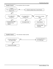
... Trouble 3 The compressor always operate. set lower than Room NO Temp.-0.5°C? YES • Check the RY-COMP. • Check the wiring Diagram. YES • Exchange IC01M. YES • Check the RY-COMP. • Connect LEAD Wire to lower Number. Troubleshooting Guide Is setting Temp. Is the voltage No.11 NO of NO RY-COMP all right? Is the wire connection of IC01M 0V? Service Manual 13...
... Trouble 3 The compressor always operate. set lower than Room NO Temp.-0.5°C? YES • Check the RY-COMP. • Check the wiring Diagram. YES • Exchange IC01M. YES • Check the RY-COMP. • Connect LEAD Wire to lower Number. Troubleshooting Guide Is setting Temp. Is the voltage No.11 NO of NO RY-COMP all right? Is the wire connection of IC01M 0V? Service Manual 13...

Service Manual
Page 14
... 3 or 4 NO of Energy Saver does not operate. YES Is the voltage NO.13 or 14 or 15 NO of SW1 NO set to left position? Is the Knob of IC01M 0V? YES Is the voltage No.1 of NO CN-DISP1 of Main & Display PCB. 14 Window Air Conditioner YES • Reference to OWNER'S MANUAL. • Set the Knob of SW1...
... 3 or 4 NO of Energy Saver does not operate. YES Is the voltage NO.13 or 14 or 15 NO of SW1 NO set to left position? Is the Knob of IC01M 0V? YES Is the voltage No.1 of NO CN-DISP1 of Main & Display PCB. 14 Window Air Conditioner YES • Reference to OWNER'S MANUAL. • Set the Knob of SW1...

Service Manual
Page 16
...Troubleshooting Guide LWC1264PBG/PHG, LWC1264VBS/QBG Possible Trouble 1 The unit does not operate. Is the reset circuit all right? YES Is output Voltage of IC1 NO DC 5V? YES Exchange Main PCB Ass'y. • Exchange IC4, C07. • Connect connector exactly. • Check the PCB pattern. 16 Window Air Conditioner... NO (The No.16 of IC3 NO DC 5V? YES • Check the Fuse. • Check the wiring diagram. output? Is output Voltage of IC1 is 5V.) YES Is the connection between NO Main and Display all right?
...Troubleshooting Guide LWC1264PBG/PHG, LWC1264VBS/QBG Possible Trouble 1 The unit does not operate. Is the reset circuit all right? YES Is output Voltage of IC1 NO DC 5V? YES Exchange Main PCB Ass'y. • Exchange IC4, C07. • Connect connector exactly. • Check the PCB pattern. 16 Window Air Conditioner... NO (The No.16 of IC3 NO DC 5V? YES • Check the Fuse. • Check the wiring diagram. output? Is output Voltage of IC1 is 5V.) YES Is the connection between NO Main and Display all right?
Service Manual
Page 17
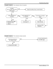
... RY-COMP again. set lower than Room Temp.-0.5°C? YES • Select the setting Temp. Possible Trouble 3 The compressor always operate. YES • Check the RY-COMP. • Connect LEAD Wire to lower Number. YES • Check the RY-COMP. • Check the wiring Diagram. • Exchange IC7. • Wait 3 Minutes. • Exchange MAIN PCB Ass'y. Possible Trouble 2 The compressor does not operate. Troubleshooting Guide Is setting NO Temp.
... RY-COMP again. set lower than Room Temp.-0.5°C? YES • Select the setting Temp. Possible Trouble 3 The compressor always operate. YES • Check the RY-COMP. • Connect LEAD Wire to lower Number. YES • Check the RY-COMP. • Check the wiring Diagram. • Exchange IC7. • Wait 3 Minutes. • Exchange MAIN PCB Ass'y. Possible Trouble 2 The compressor does not operate. Troubleshooting Guide Is setting NO Temp.
Service Manual
Page 18
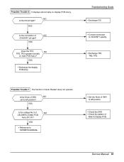
YES • Check the RY-High or RY-Low. • Check the wiring diagram. YES Is the connection of IC7 0V? YES Is the voltage NO.14 or 15 NO of NO CN-DISP2 all right?... Receiver Ass'y. • Exchange IC1. • Exchange IC7. • Exchange the battery. ••CChheecckkththeePPCCBBppaattteterrnn.. • Connect connector to CN-DISP2 exactly. 18 Window Air Conditioner Possible Trouble 5 Remote controller does not operate. Troubleshooting Guide Possible Trouble 4 FAN does not operate. YES Is the voltage No.7 NO of CN-DISP2 on Main PCB Ass'y DC 5V?
YES • Check the RY-High or RY-Low. • Check the wiring diagram. YES Is the connection of IC7 0V? YES Is the voltage NO.14 or 15 NO of NO CN-DISP2 all right?... Receiver Ass'y. • Exchange IC1. • Exchange IC7. • Exchange the battery. ••CChheecckkththeePPCCBBppaattteterrnn.. • Connect connector to CN-DISP2 exactly. 18 Window Air Conditioner Possible Trouble 5 Remote controller does not operate. Troubleshooting Guide Possible Trouble 4 FAN does not operate. YES Is the voltage No.7 NO of CN-DISP2 on Main PCB Ass'y DC 5V?
Service Manual
Page 19
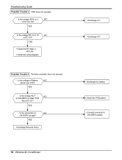
YES • Exchange the display PCB Ass'y. Troubleshooting Guide • Exchange IC6. • Connect connector to left position? YES • Reference to OWNER'S MANUAL. • Set the Knob of SW1 to CN-DISP1 exactly. • Exchange TR1, TR2, TR3. YES Is the voltage No.3 of NO CN-DISP2 of Auto Restart does not operate. Possible Trouble 6 It displays abnormally on main...
YES • Exchange the display PCB Ass'y. Troubleshooting Guide • Exchange IC6. • Connect connector to left position? YES • Reference to OWNER'S MANUAL. • Set the Knob of SW1 to CN-DISP1 exactly. • Exchange TR1, TR2, TR3. YES Is the voltage No.3 of NO CN-DISP2 of Auto Restart does not operate. Possible Trouble 6 It displays abnormally on main...
Service Manual
Page 20
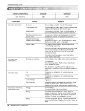
... voltage at outlet. Replace cord if circuit is open. 20 Window Air Conditioner Fan blade hitting shroud or blower wheel hitting scroll. Units using slinger ring for identification, and replace. Check bearings. If not, replace fan motor. Pay attention to any change , replace the motor. If wires are off, refer to wiring diagram for condenser fan must have 1/4 to 5/16 inch clearance to the base. Troubleshooting Guide Room Air Conditioner Voltage Limits NAME PLATE RATING 220~240±...
... voltage at outlet. Replace cord if circuit is open. 20 Window Air Conditioner Fan blade hitting shroud or blower wheel hitting scroll. Units using slinger ring for identification, and replace. Check bearings. If not, replace fan motor. Pay attention to any change , replace the motor. If wires are off, refer to wiring diagram for condenser fan must have 1/4 to 5/16 inch clearance to the base. Troubleshooting Guide Room Air Conditioner Voltage Limits NAME PLATE RATING 220~240±...
Service Manual
Page 21
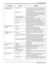
... the terminals. Service Manual 21 Check continuity of the thermistor. Check the continuity of the thermostat. Clean the interior base before servicing.) Compressor Overload Voltage Overload Fan motor Condenser air flow restriction Condenser fins (damaged) Capacitor Wiring Refrigerating system Air filter Exhaust damper door Unit undersized Turbo or fan Copper tubing Check the position of manufacturers rating. Test capacitor. Check the set TEMP control to this setting and restart unit. If the turbo or fan is open . Troubleshooting Guide COMPLAINT CAUSE...
... the terminals. Service Manual 21 Check continuity of the thermistor. Check the continuity of the thermostat. Clean the interior base before servicing.) Compressor Overload Voltage Overload Fan motor Condenser air flow restriction Condenser fins (damaged) Capacitor Wiring Refrigerating system Air filter Exhaust damper door Unit undersized Turbo or fan Copper tubing Check the position of manufacturers rating. Test capacitor. Check the set TEMP control to this setting and restart unit. If the turbo or fan is open . Troubleshooting Guide COMPLAINT CAUSE...


