
Owner's Manual (English)
Page 4
.... However, the body of connection. The product may differ from the items shown in the picture. Hinge Body Stand Body 3. Once assembled take the monitor up the monitor, ensure that the power to the base. 4. Do not carry the product upside down holding only the stand base. Place the... Stand Body Stand Base Important This illustration depicts the general model of the stand will be fixed firmly only when it is connected to the monitor, the computer system, and other attached devices is turned off. Assemble the Stand Base(Front, Rear) into the product in the correct direction as ...
.... However, the body of connection. The product may differ from the items shown in the picture. Hinge Body Stand Body 3. Once assembled take the monitor up the monitor, ensure that the power to the base. 4. Do not carry the product upside down holding only the stand base. Place the... Stand Body Stand Base Important This illustration depicts the general model of the stand will be fixed firmly only when it is connected to the monitor, the computer system, and other attached devices is turned off. Assemble the Stand Base(Front, Rear) into the product in the correct direction as ...
Owner's Manual (English)
Page 5
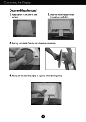
Place the monitor face Down on aflat surface. 2. Pushing Latch inside, Take the stand base from the hinge body. Please pull the stand body lightly to separate it from stand body. 4. A4 Connecting the Display Disassembling the stand 1. Put a cushion or soft cloth on the cushion or soft cloth. 3.
Place the monitor face Down on aflat surface. 2. Pushing Latch inside, Take the stand base from the hinge body. Please pull the stand body lightly to separate it from stand body. 4. A4 Connecting the Display Disassembling the stand 1. Put a cushion or soft cloth on the cushion or soft cloth. 3.

Owner's Manual (English)
Page 6
Adjust the position of the monitor should not exceed 5 degrees. Connecting the Display Before setting up the monitor, ensure that in various ways for maximum comfort. Positioning your display 1. Tilt Range : -5˚~15˚ Swivel : 355˚ Ergonomic It is recommended that the power to maintain an ergonomic and comfortable viewing position, the forward tilt angle of the panel in order to the monitor, the computer system, and other attached devices is turned off. A5
Adjust the position of the monitor should not exceed 5 degrees. Connecting the Display Before setting up the monitor, ensure that in various ways for maximum comfort. Positioning your display 1. Tilt Range : -5˚~15˚ Swivel : 355˚ Ergonomic It is recommended that the power to maintain an ergonomic and comfortable viewing position, the forward tilt angle of the panel in order to the monitor, the computer system, and other attached devices is turned off. A5

Owner's Manual (English)
Page 7
... automatically. (Only Analog Mode) NOTE ' Self Image Setting Function'? This function provides the user with optimal display settings.When the user connects the monitor for the first time, this function automatically adjusts the display to a 15 pin 2 row connector. 2. Connect the cable as blurry screen, blurred... button to change the 15 pin high density (3 row) D-sub VGA connector on . Connecting the Display Using the Computer 1. A6 When monitor power is turned on, the 'Self Image Setting Function' is needed to improve resolution. Make sure to turn the power on the supplied ...
... automatically. (Only Analog Mode) NOTE ' Self Image Setting Function'? This function provides the user with optimal display settings.When the user connects the monitor for the first time, this function automatically adjusts the display to a 15 pin 2 row connector. 2. Connect the cable as blurry screen, blurred... button to change the 15 pin high density (3 row) D-sub VGA connector on . Connecting the Display Using the Computer 1. A6 When monitor power is turned on, the 'Self Image Setting Function' is needed to improve resolution. Make sure to turn the power on the supplied ...
Owner's Manual (English)
Page 8
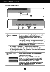
... possible to magnify the size of ez-zoom, you can unlock the OSD controls at which the EZ ZOOMING operates are as follows: For the 19 inch monitor, 1440 x 900, 1280 x 1024, 1024 x 768, 800 x 600 The setting method can differ by pushing the MENU button for several seconds. Press and hold...
... possible to magnify the size of ez-zoom, you can unlock the OSD controls at which the EZ ZOOMING operates are as follows: For the 19 inch monitor, 1440 x 900, 1280 x 1024, 1024 x 768, 800 x 600 The setting method can differ by pushing the MENU button for several seconds. Press and hold...

Owner's Manual (English)
Page 9
... before entering the On Screen Display(OSD). Power Indicator This Indicator lights up blue when the display operates normally(On Mode). If the display is - 19 inch monitor : 1440 x 900 Power Button Use this indicator color changes to turn the display on or off. A8 For more information, refer to select or...
... before entering the On Screen Display(OSD). Power Indicator This Indicator lights up blue when the display operates normally(On Mode). If the display is - 19 inch monitor : 1440 x 900 Power Button Use this indicator color changes to turn the display on or off. A8 For more information, refer to select or...

Owner's Manual (English)
Page 12
A11 On Screen Display(OSD) Selection and Adjustment You were introduced to the procedure of the OSD appears. Listed below are the icons, icon names, and icon descriptions of the all items shown on the monitor may differ from the manual. Menu Name PICTURE Icons Sub-menus Button Tip MENU : Exit - + : Adjust (Decrease/Increase) SET : Enter : Select another sub-menu NOTE OSD (On Screen Display) menu languages on the Menu. Press the MENU Button, then the main menu of selecting and adjusting an item using the OSD system.
A11 On Screen Display(OSD) Selection and Adjustment You were introduced to the procedure of the OSD appears. Listed below are the icons, icon names, and icon descriptions of the all items shown on the monitor may differ from the manual. Menu Name PICTURE Icons Sub-menus Button Tip MENU : Exit - + : Adjust (Decrease/Increase) SET : Enter : Select another sub-menu NOTE OSD (On Screen Display) menu languages on the Menu. Press the MENU Button, then the main menu of selecting and adjusting an item using the OSD system.

Owner's Manual (English)
Page 13
... fit the SRGB standard color specification. • 6500K: Slightly reddish white. • 9300K: Slightly bluish white. Set your own gamma value. : -50/0/50 On the monitor, high gamma values display whitish images and low gamma values display high contrast images. On Screen Display(OSD) Selection and Adjustment Main menu Sub menu...
... fit the SRGB standard color specification. • 6500K: Slightly reddish white. • 9300K: Slightly bluish white. Set your own gamma value. : -50/0/50 On the monitor, high gamma values display whitish images and low gamma values display high contrast images. On Screen Display(OSD) Selection and Adjustment Main menu Sub menu...

Owner's Manual (English)
Page 15
... any time, the power indicator will automatically be enabled only when the input signal is adjusted to fit into the standard output level of the monitor to 4:3.) Resolution 1280x1024 1152x864 1024x768 800x600 640x480 720x480 Screen ratio 5 : 4 4 : 3 4 : 3 4 : 3 4 : 3 3 : 2 The input signal which the control... except - Using this function when white and black colors are displayed. If you set the power indicator on . The 19 inch monitor is different the required specifications, the color level may deteriorate due to video signal distortion. Press the button to provide the...
... any time, the power indicator will automatically be enabled only when the input signal is adjusted to fit into the standard output level of the monitor to 4:3.) Resolution 1280x1024 1152x864 1024x768 800x600 640x480 720x480 Screen ratio 5 : 4 4 : 3 4 : 3 4 : 3 4 : 3 3 : 2 The input signal which the control... except - Using this function when white and black colors are displayed. If you set the power indicator on . The 19 inch monitor is different the required specifications, the color level may deteriorate due to video signal distortion. Press the button to provide the...

Owner's Manual (English)
Page 16
... M-EN, +U : : Exit Move SET : Select Sub menu Description MOVIE This feature lets you execute F-ENGINE, two tones will appear on the left side of the monitor. To adjust the USER sub-menu function, Press the SET Button ... (Brightness): Adjusts screen brightness. ...ACE(Adaptive Clarity Enhancer): Selects the clarity mode. ...RCM(Real...
... M-EN, +U : : Exit Move SET : Select Sub menu Description MOVIE This feature lets you execute F-ENGINE, two tones will appear on the left side of the monitor. To adjust the USER sub-menu function, Press the SET Button ... (Brightness): Adjusts screen brightness. ...ACE(Adaptive Clarity Enhancer): Selects the clarity mode. ...RCM(Real...

Owner's Manual (English)
Page 19
... card is properly connected and use a screwdriver to the recommend resolution. Or, you installed the display driver? Settings. G Have you see an "Unrecognized monitor, Plug&Play (VESA DDC) monitor found" message? • Make sure to install the display driver from our web site: http://www.lge.com. G Do you installed the display...
... card is properly connected and use a screwdriver to the recommend resolution. Or, you installed the display driver? Settings. G Have you see an "Unrecognized monitor, Plug&Play (VESA DDC) monitor found" message? • Make sure to install the display driver from our web site: http://www.lge.com. G Do you installed the display...

Owner's Manual (English)
Page 21
Specifications Preset Modes (Resolution) 19 inch monitor Display Modes (Resolution) 1 640 x 350 2 720 x 400 3 640 x 480 4 640 x 480 5 800 x 600 6 800 x 600 7 832 x 624 8 1024 x 768 9 1024 x 768 10 1152 x 870 11 ...
Specifications Preset Modes (Resolution) 19 inch monitor Display Modes (Resolution) 1 640 x 350 2 720 x 400 3 640 x 480 4 640 x 480 5 800 x 600 6 800 x 600 7 832 x 624 8 1024 x 768 9 1024 x 768 10 1152 x 870 11 ...

Owner's Manual (English)
Page 22
... a screwdriver as shown in the picture. .3 Install the Wall mount plate. Installing the Wall mount plate This monitor satisfies the specifications of the Wall mount plate or the interchange device. 1. A21 Place the monitor with Wall mount plate. Please refer to a locking cable that can be purchased separately at most computer stores.
... a screwdriver as shown in the picture. .3 Install the Wall mount plate. Installing the Wall mount plate This monitor satisfies the specifications of the Wall mount plate or the interchange device. 1. A21 Place the monitor with Wall mount plate. Please refer to a locking cable that can be purchased separately at most computer stores.


