User Guide
Page 4
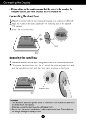
... holding only the stand base. To remove the stand base, hold the bottom of connection. Once you connect the stand base, try not to the monitor, the computer system, and other hand, as shown in the figure. Connecting the stand base 1. A3 Align the hooks on a cushion or soft cloth. ...and pull the base bottom latch with the matching slots in the picture. Connecting the Display Before setting up the monitor, ensure that the power to disconnect it. Place the monitor with its front facing downward on the stand base with the other attached devices is turned off. Insert the ...
... holding only the stand base. To remove the stand base, hold the bottom of connection. Once you connect the stand base, try not to the monitor, the computer system, and other hand, as shown in the figure. Connecting the stand base 1. A3 Align the hooks on a cushion or soft cloth. ...and pull the base bottom latch with the matching slots in the picture. Connecting the Display Before setting up the monitor, ensure that the power to disconnect it. Place the monitor with its front facing downward on the stand base with the other attached devices is turned off. Insert the ...
User Guide
Page 5
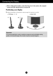
Adjust the position of the panel in order to the monitor, the computer system, and other attached devices is recommended that the power to maintain an ergonomic and comfortable viewing position, the forward tilt angle of the monitor should not exceed 5 degrees. A4 Tilt Range : -5˚~20˚ Swivel :350˚ Ergonomic It is turned off. Connecting the Display Before setting up the monitor, ensure that in various ways for maximum comfort. Positioning your display 1.
Adjust the position of the panel in order to the monitor, the computer system, and other attached devices is recommended that the power to maintain an ergonomic and comfortable viewing position, the forward tilt angle of the monitor should not exceed 5 degrees. A4 Tilt Range : -5˚~20˚ Swivel :350˚ Ergonomic It is turned off. Connecting the Display Before setting up the monitor, ensure that in various ways for maximum comfort. Positioning your display 1.
User Guide
Page 6
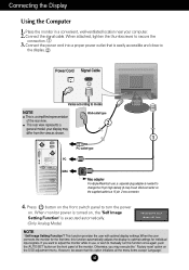
...Power Cord Signal Cable Varies according to secure the connection. 3. This function provides the user with optimal display settings.When the user connects the monitor for the first time, this function once again, push the 'AUTO/SET' button on , the 'Self Image Setting Function' is needed...automatically adjusts the display to a 15 pin 2 row connector. 4. Otherwise, you want to turn the power on the OSD adjustment menu. Place the monitor in use , a separate plug adapter is executed automatically. (Only Analog Mode) NOTE ' Self Image Setting Function'? However, be aware that is a...
...Power Cord Signal Cable Varies according to secure the connection. 3. This function provides the user with optimal display settings.When the user connects the monitor for the first time, this function once again, push the 'AUTO/SET' button on , the 'Self Image Setting Function' is needed...automatically adjusts the display to a 15 pin 2 row connector. 4. Otherwise, you want to turn the power on the OSD adjustment menu. Place the monitor in use , a separate plug adapter is executed automatically. (Only Analog Mode) NOTE ' Self Image Setting Function'? However, be aware that is a...
User Guide
Page 8
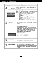
The best display mode is 17 inch monitor : 1280x1024 19 inch monitor : 1280x1024 Power Button Use this indicator color changes to amber. Power Indicator This Indicator lights up green when the display operates normally(On Mode). If ...
The best display mode is 17 inch monitor : 1280x1024 19 inch monitor : 1280x1024 Power Button Use this indicator color changes to amber. Power Indicator This Indicator lights up green when the display operates normally(On Mode). If ...

User Guide
Page 11
Press the MENU Button, then the main menu of selecting and adjusting an item using the OSD system. On Screen Display(OSD) Selection and Adjustment You were introduced to the procedure of the OSD appears. A10 Menu Name PICTURE Icons Sub-menus Button Tip MENU : Exit - + : Adjust (Decrease/Increase) SET : Enter : Select another sub-menu NOTE OSD (On Screen Display) menu languages on the Menu. Listed below are the icons, icon names, and icon descriptions of the all items shown on the monitor may differ from the manual.
Press the MENU Button, then the main menu of selecting and adjusting an item using the OSD system. On Screen Display(OSD) Selection and Adjustment You were introduced to the procedure of the OSD appears. A10 Menu Name PICTURE Icons Sub-menus Button Tip MENU : Exit - + : Adjust (Decrease/Increase) SET : Enter : Select another sub-menu NOTE OSD (On Screen Display) menu languages on the Menu. Listed below are the icons, icon names, and icon descriptions of the all items shown on the monitor may differ from the manual.
User Guide
Page 12
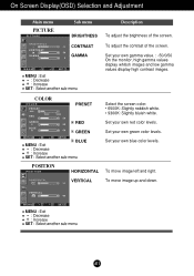
... color levels. GREEN Set your own blue color levels. To move image up and down. RED Set your own gamma value. : -50/0/50 On the monitor, high gamma values display whitish images and low gamma values display high contrast images. MENU : Exit +- : Decrease : Increase SET : Select another sub-menu To adjust...
... color levels. GREEN Set your own blue color levels. To move image up and down. RED Set your own gamma value. : -50/0/50 On the monitor, high gamma values display whitish images and low gamma values display high contrast images. MENU : Exit +- : Decrease : Increase SET : Select another sub-menu To adjust...
User Guide
Page 13
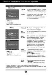
... side of characters. Press the button to ON or OFF. If you to remove any horizontal noise and clear or sharpen the image of the monitor to reset immediately. FACTORY RESET Restore all factory default settings except "LANGUAGE." This item allows you set the power indicator on the screen.
... side of characters. Press the button to ON or OFF. If you to remove any horizontal noise and clear or sharpen the image of the monitor to reset immediately. FACTORY RESET Restore all factory default settings except "LANGUAGE." This item allows you set the power indicator on the screen.
User Guide
Page 16
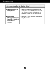
Or, you installed the display driver? Do you installed the display driver? Make sure to install the display driver from our web site: http://www.lge.com. Be sure to check if the video card supports Plug&Play function. A15 Troubleshooting Have you see an "Unrecognized monitor, Plug&Play (VESA DDC) monitor found" message? Have you can also download the driver from the display driver CD (or diskette) that comes with your display.
Or, you installed the display driver? Do you installed the display driver? Make sure to install the display driver from our web site: http://www.lge.com. Be sure to check if the video card supports Plug&Play function. A15 Troubleshooting Have you see an "Unrecognized monitor, Plug&Play (VESA DDC) monitor found" message? Have you can also download the driver from the display driver CD (or diskette) that comes with your display.
User Guide
Page 20
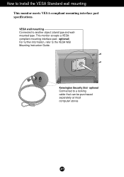
optional Connected to Install the VESA Standard wall mounting This monitor meets VESA-compliant mounting interface pad specifications. How to a locking cable that can be purchased separately at most computer stores A19 optional) For further information, refer to another object (stand type and wallmounted type. Kensington Security Slot- VESA wall mounting Connected to the VESA Wall Mounting Instruction Guide. This monitor accepts a VESAcompliant mounting interface pad.-
optional Connected to Install the VESA Standard wall mounting This monitor meets VESA-compliant mounting interface pad specifications. How to a locking cable that can be purchased separately at most computer stores A19 optional) For further information, refer to another object (stand type and wallmounted type. Kensington Security Slot- VESA wall mounting Connected to the VESA Wall Mounting Instruction Guide. This monitor accepts a VESAcompliant mounting interface pad.-


