
Owner's Manual (English)
Page 4
...you push it until you hear it "click". The product may differ from the items shown in the picture. Connecting the stand 1. Place the monitor with its front facing downward on a soft cloth. 2. Stand Body 3. Do not carry the product upside down holding only the stand base. Connecting...face the front side Stand Base Stand Body Important This illustration depicts the general model of connection. Once assembled take the monitor up the monitor, ensure that the power to the monitor, the computer system, and other attached devices is turned off. A3 Assemble the Stand Base(Front, Rear) into ...
...you push it until you hear it "click". The product may differ from the items shown in the picture. Connecting the stand 1. Place the monitor with its front facing downward on a soft cloth. 2. Stand Body 3. Do not carry the product upside down holding only the stand base. Connecting...face the front side Stand Base Stand Body Important This illustration depicts the general model of connection. Once assembled take the monitor up the monitor, ensure that the power to the monitor, the computer system, and other attached devices is turned off. A3 Assemble the Stand Base(Front, Rear) into ...
Owner's Manual (English)
Page 5
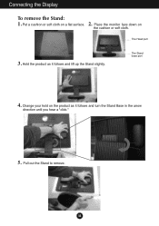
Hold the product as it follows and lift up the Stand slightly. The Head part 3. Pull out the Stand to remove. The Stand base part 4. A4 Place the monitor face down on a flat surface. Put a cushion or soft cloth on the cushion or soft cloth. Connecting the Display To remove the Stand: 1. 2. Change your hold on the product as it follows and turn the Stand Base in the arrow direction until you hear a "click." 5.
Hold the product as it follows and lift up the Stand slightly. The Head part 3. Pull out the Stand to remove. The Stand base part 4. A4 Place the monitor face down on a flat surface. Put a cushion or soft cloth on the cushion or soft cloth. Connecting the Display To remove the Stand: 1. 2. Change your hold on the product as it follows and turn the Stand Base in the arrow direction until you hear a "click." 5.

Owner's Manual (English)
Page 7
...hurt your display 1. Ergonomic It is recommended that the power to maintain an ergonomic and comfortable viewing position, the forward tilt angle of the monitor and the stand body . Tilt Range: -5˚~20˚ Swivel : 355˚(The feature is turned off. Connecting the Display Before setting up ...the monitor, ensure that in various ways for all countries) 20 Warning: When adjusting the angle of the screen, do not put your finger in between ...
...hurt your display 1. Ergonomic It is recommended that the power to maintain an ergonomic and comfortable viewing position, the forward tilt angle of the monitor and the stand body . Tilt Range: -5˚~20˚ Swivel : 355˚(The feature is turned off. Connecting the Display Before setting up ...the monitor, ensure that in various ways for all countries) 20 Warning: When adjusting the angle of the screen, do not put your finger in between ...
Owner's Manual (English)
Page 8
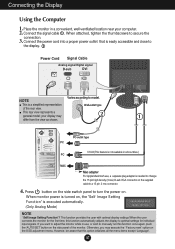
... power on the side panel of the rear view. This function provides the user with optimal display settings.When the user connects the monitor for individual input signals. A7 Connect the power cord into a proper power outlet that this option initializes all countries.) PC MAC Mac...pin high density (3 row) D-sub VGA connector on the OSD adjustment menu. Connect the signal cable 1 . Otherwise, you want to adjust the monitor while in a convenient, well-ventilated location near your display may execute the ' Factory reset' option on the supplied cable to optimal settings for the...
... power on the side panel of the rear view. This function provides the user with optimal display settings.When the user connects the monitor for individual input signals. A7 Connect the power cord into a proper power outlet that this option initializes all countries.) PC MAC Mac...pin high density (3 row) D-sub VGA connector on the OSD adjustment menu. Connect the signal cable 1 . Otherwise, you want to adjust the monitor while in a convenient, well-ventilated location near your display may execute the ' Factory reset' option on the supplied cable to optimal settings for the...

Owner's Manual (English)
Page 10
... will automatically adjust your display settings, always press the AUTO/SET button before entering the On Screen Display(OSD). If the display is 17 inch monitor : 1280 x 1024 19 inch monitor : 1280 x 1024 Power Button Use this indicator color changes to the ideal settings for the current screen resolution size (display mode).
... will automatically adjust your display settings, always press the AUTO/SET button before entering the On Screen Display(OSD). If the display is 17 inch monitor : 1280 x 1024 19 inch monitor : 1280 x 1024 Power Button Use this indicator color changes to the ideal settings for the current screen resolution size (display mode).
Owner's Manual (English)
Page 13
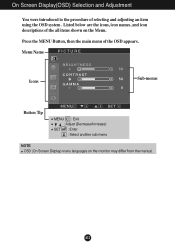
On Screen Display(OSD) Selection and Adjustment You were introduced to the procedure of the OSD appears. Menu Name PICTURE Icons Sub-menus Button Tip MENU : Exit : Adjust (Decrease/Increase) SET : Enter : Select another sub-menu NOTE OSD (On Screen Display) menu languages on the Menu. Press the MENU Button, then the main menu of selecting and adjusting an item using the OSD system. A12 Listed below are the icons, icon names, and icon descriptions of the all items shown on the monitor may differ from the manual.
On Screen Display(OSD) Selection and Adjustment You were introduced to the procedure of the OSD appears. Menu Name PICTURE Icons Sub-menus Button Tip MENU : Exit : Adjust (Decrease/Increase) SET : Enter : Select another sub-menu NOTE OSD (On Screen Display) menu languages on the Menu. Press the MENU Button, then the main menu of selecting and adjusting an item using the OSD system. A12 Listed below are the icons, icon names, and icon descriptions of the all items shown on the monitor may differ from the manual.

Owner's Manual (English)
Page 14
.... • 6500K: Slightly reddish white. • 9300K: Slightly bluish white. Set your own blue color levels. Set your own gamma value. : -50/0/50 On the monitor, high gamma values display whitish images and low gamma values display high contrast images. POSITION POSITION HORIZONTAL VERTICAL To move image up and down. To...
.... • 6500K: Slightly reddish white. • 9300K: Slightly bluish white. Set your own blue color levels. Set your own gamma value. : -50/0/50 On the monitor, high gamma values display whitish images and low gamma values display high contrast images. POSITION POSITION HORIZONTAL VERTICAL To move image up and down. To...

Owner's Manual (English)
Page 15
... set the power indicator on . If you to video signal distortion. If you set OFF, it will be turned on the front side of the monitor to ON or OFF. This function will go off. SETUP WHITE BALANCE If the output of the video card is different the required specifications, the...
... set the power indicator on . If you to video signal distortion. If you set OFF, it will be turned on the front side of the monitor to ON or OFF. This function will go off. SETUP WHITE BALANCE If the output of the video card is different the required specifications, the...
Owner's Manual (English)
Page 16
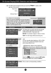
... the buttons. Screen when applied Screen when not applied Main menu Sub menu Description MOVIE This feature lets you touch the right side of the monitor. The applied screen will appear on the left side, whereas the non-applied screen will appear on the screen as shown. On Screen Display(OSD...
... the buttons. Screen when applied Screen when not applied Main menu Sub menu Description MOVIE This feature lets you touch the right side of the monitor. The applied screen will appear on the left side, whereas the non-applied screen will appear on the screen as shown. On Screen Display(OSD...
Owner's Manual (English)
Page 19
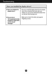
G Have you see an "Unrecognized monitor, Plug&Play (VESA DDC) monitor found" message? • Make sure to install the display driver from our web site: http://www.lge.com. A18 G Do you installed the display driver? • Be sure to check if the video card supports Plug&Play function. Or, you installed the display driver? Troubleshooting Have you can also download the driver from the display driver CD (or diskette) that comes with your display.
G Have you see an "Unrecognized monitor, Plug&Play (VESA DDC) monitor found" message? • Make sure to install the display driver from our web site: http://www.lge.com. A18 G Do you installed the display driver? • Be sure to check if the video card supports Plug&Play function. Or, you installed the display driver? Troubleshooting Have you can also download the driver from the display driver CD (or diskette) that comes with your display.

Owner's Manual (English)
Page 24
The Stand base part 4. A23 Pull out the Stand to remove. Installing the Wall mount plate This monitor satisfies the specifications of the Wall mount plate or the interchange device. 1. 2. Hold the product as it follows and lift up the Stand slightly. Change your hold on the product as it follows and turn the Stand Base in the arrow direction until you hear a "click." 5. Place the monitor face down on a flat surface. The Head part 3. Put a cushion or soft cloth on the cushion or soft cloth.
The Stand base part 4. A23 Pull out the Stand to remove. Installing the Wall mount plate This monitor satisfies the specifications of the Wall mount plate or the interchange device. 1. 2. Hold the product as it follows and lift up the Stand slightly. Change your hold on the product as it follows and turn the Stand Base in the arrow direction until you hear a "click." 5. Place the monitor face down on a flat surface. The Head part 3. Put a cushion or soft cloth on the cushion or soft cloth.

Service Manual
Page 1
Internal Use Only Website:http://biz.LGservice.com COLOR MONITOR SERVICE MANUAL CHASSIS NO. : LM57B MODEL: L1733TR (L1733TR-SFQ.A**MQP) L1933TR (L1933TR-SFQ.A**MQP,A**RQP) ( ) **Same model for Service CAUTION BEFORE SERVICING THE UNIT, READ THE SAFETY PRECAUTIONS IN THIS MANUAL. *To apply the MSTAR Chip.
Internal Use Only Website:http://biz.LGservice.com COLOR MONITOR SERVICE MANUAL CHASSIS NO. : LM57B MODEL: L1733TR (L1733TR-SFQ.A**MQP) L1933TR (L1933TR-SFQ.A**MQP,A**RQP) ( ) **Same model for Service CAUTION BEFORE SERVICING THE UNIT, READ THE SAFETY PRECAUTIONS IN THIS MANUAL. *To apply the MSTAR Chip.

Service Manual
Page 3
Copyright 2007 LG Electronics. Only for training and service purposes -3- It is essential that ...8226; The module not be replaced with care wires or connectors of the inverter circuit. TAKE CARE DURING HANDLING THE LCD MODULE WITH BACKLIGHT UNIT. • Must mount the module using mounting holes arranged in four corners. • Do... All right reserved. PRECAUTION WARNING FOR THE SAFETY-RELATED COMPONENT. • There are some special components used in LCD monitor that are grounded through wrist band. • Do not leave the module in high temperature and in damage to ...
Copyright 2007 LG Electronics. Only for training and service purposes -3- It is essential that ...8226; The module not be replaced with care wires or connectors of the inverter circuit. TAKE CARE DURING HANDLING THE LCD MODULE WITH BACKLIGHT UNIT. • Must mount the module using mounting holes arranged in four corners. • Do... All right reserved. PRECAUTION WARNING FOR THE SAFETY-RELATED COMPONENT. • There are some special components used in LCD monitor that are grounded through wrist band. • Do not leave the module in high temperature and in damage to ...

Service Manual
Page 8
Only for training and service purposes -8- DISASSEMBLY-Set # 1 # 2 Soft pad on the table. # 3 Monitor on the pad. # 4-1 Pull up the stand part. # 4-2 Hold the head & stand base and then Twist Stand until "Click". # 5 Separate head & stand Copyright 2007 LG Electronics. Inc. LGE Internal Use Only All right reserved.
Only for training and service purposes -8- DISASSEMBLY-Set # 1 # 2 Soft pad on the table. # 3 Monitor on the pad. # 4-1 Pull up the stand part. # 4-2 Hold the head & stand base and then Twist Stand until "Click". # 5 Separate head & stand Copyright 2007 LG Electronics. Inc. LGE Internal Use Only All right reserved.

Service Manual
Page 15
This part contains of course the primary protection fuse. 2. Energy Transfer. Copyright 2007 LG Electronics. EMI components. This part function is for transfer the input AC voltage to a DC voltage through a photo transistor to ...HVDC SWITCHING TRANSFORMER 100KHz 12V OUTPUT RECTIFIER AND FILTER 5V GND PWM CONTROL CIRCUIT PRIMARY PHOTO-COUPLER ISOLATION SIGNAL COLLENT- This part function is also monitor by this part. 5. ION SECONDARY 12V INVERTER CIRCUIT High Voltage Operation description_LIPS 1. This part function is for training and service purposes - ...
This part contains of course the primary protection fuse. 2. Energy Transfer. Copyright 2007 LG Electronics. EMI components. This part function is for transfer the input AC voltage to a DC voltage through a photo transistor to ...HVDC SWITCHING TRANSFORMER 100KHz 12V OUTPUT RECTIFIER AND FILTER 5V GND PWM CONTROL CIRCUIT PRIMARY PHOTO-COUPLER ISOLATION SIGNAL COLLENT- This part function is also monitor by this part. 5. ION SECONDARY 12V INVERTER CIRCUIT High Voltage Operation description_LIPS 1. This part function is for training and service purposes - ...

Service Manual
Page 16
...V1.0 User Manual Operating System: MS Windows 98, 2000, XP Port Setup: Windows 98 => Don't need setup Windows 2000, XP => Need to LCD Monitor only. 1. f) Click Exit button. Port Setup a) Copy "UserPort.sys" file to "c:\WINNT\system32\drivers" folder b) Run Userport.exe 2. LGE Internal... Use Only Copyright 2007 LG Electronics. EDID Read & Write 1) Run WinEDID.exe c) Remove all default number d) Add 300-3FF 2) Edit Week of Manufacture, Year of Manufacture, ...
...V1.0 User Manual Operating System: MS Windows 98, 2000, XP Port Setup: Windows 98 => Don't need setup Windows 2000, XP => Need to LCD Monitor only. 1. f) Click Exit button. Port Setup a) Copy "UserPort.sys" file to "c:\WINNT\system32\drivers" folder b) Run Userport.exe 2. LGE Internal... Use Only Copyright 2007 LG Electronics. EDID Read & Write 1) Run WinEDID.exe c) Remove all default number d) Add 300-3FF 2) Edit Week of Manufacture, Year of Manufacture, ...

Service Manual
Page 17
... training and service purposes - 17 - Video Signal Generator Control Line IBM Compatible PC 15 10 5 PARALLEL PORT Not used RS232C PARALLEL OFF ON 5V C F VGS A MONITOR B V-SYNC ST POWER Power inlet (required) 220 Power Select Switch (110V/220V) Power LED E ST Switch F V-Sync On/Off Switch (Switch must be ON.) A 9 11... and Automatically sets the gain and offset value. f) R/G/B-6500K : Allows you to set the R/G/B-6500K value manually. LGE Internal Use Only Cable Connection Copyright 2007 LG Electronics. SERVICE OSD 1) Turn off ).
... training and service purposes - 17 - Video Signal Generator Control Line IBM Compatible PC 15 10 5 PARALLEL PORT Not used RS232C PARALLEL OFF ON 5V C F VGS A MONITOR B V-SYNC ST POWER Power inlet (required) 220 Power Select Switch (110V/220V) Power LED E ST Switch F V-Sync On/Off Switch (Switch must be ON.) A 9 11... and Automatically sets the gain and offset value. f) R/G/B-6500K : Allows you to set the R/G/B-6500K value manually. LGE Internal Use Only Cable Connection Copyright 2007 LG Electronics. SERVICE OSD 1) Turn off ).


