Owner's Manual (English)
Page 4
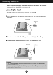
Once assembled take the monitor up the monitor, ensure that the power to the monitor, the computer system, and other attached devices is turned off. Do not carry the product upside down holding only the stand base. A3 Check the ... shown in the picture. The product may differ from the items shown in the picture. Hinge Body Stand Body 3. Your monitor may fall and get damaged or injure your foot. Place the monitor with its front facing downward on a soft cloth. 2. Connecting the Display Before setting up carefully and face the front...
Once assembled take the monitor up the monitor, ensure that the power to the monitor, the computer system, and other attached devices is turned off. Do not carry the product upside down holding only the stand base. A3 Check the ... shown in the picture. The product may differ from the items shown in the picture. Hinge Body Stand Body 3. Your monitor may fall and get damaged or injure your foot. Place the monitor with its front facing downward on a soft cloth. 2. Connecting the Display Before setting up carefully and face the front...
Owner's Manual (English)
Page 5
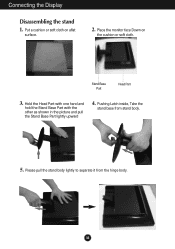
Connecting the Display Disassembling the stand 1. Place the monitor face Down on aflat surface. 2. Stand Base Part Head Part 3. Pushing Latch inside, Take the stand base from the hinge body. A4 Put a cushion or soft cloth on the cushion or soft cloth. Please pull the stand body lightly to separate it from stand body. 5. Hold the Head Part with one hand and hold the Stand Base Part with the other as shown in the picture and pull the Stand Base Part lightly upward 4.
Connecting the Display Disassembling the stand 1. Place the monitor face Down on aflat surface. 2. Stand Base Part Head Part 3. Pushing Latch inside, Take the stand base from the hinge body. A4 Put a cushion or soft cloth on the cushion or soft cloth. Please pull the stand body lightly to separate it from stand body. 5. Hold the Head Part with one hand and hold the Stand Base Part with the other as shown in the picture and pull the Stand Base Part lightly upward 4.
Owner's Manual (English)
Page 6
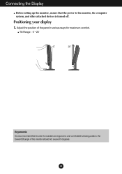
Adjust the position of the monitor should not exceed 5 degrees. A5 Positioning your display 1. Connecting the Display Before setting up the monitor, ensure that in various ways for maximum comfort. Tilt Range : -5˚~20˚ Ergonomic It is recommended that the power to maintain an ergonomic and comfortable viewing position, the forward tilt angle of the panel in order to the monitor, the computer system, and other attached devices is turned off.
Adjust the position of the monitor should not exceed 5 degrees. A5 Positioning your display 1. Connecting the Display Before setting up the monitor, ensure that in various ways for maximum comfort. Tilt Range : -5˚~20˚ Ergonomic It is recommended that the power to maintain an ergonomic and comfortable viewing position, the forward tilt angle of the panel in order to the monitor, the computer system, and other attached devices is turned off.
Owner's Manual (English)
Page 7
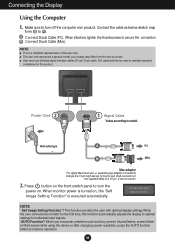
...Apple Macintosh use shielded signal interface cables (D-sub 15 pin cable, DVI cable) with optimal display settings.When the user connects the monitor for the first time, this function automatically adjusts the display to maintain standard compliance for individual input signals. 'AUTO Function? This... a general model; When attached, tighten the thumbscrews to improve resolution. B Connect Dsub Cable (Mac) NOTE This is executed automatically. When monitor power is needed to change the 15 pin high density (3 row) D-sub VGA connector on the front switch panel to turn the power ...
...Apple Macintosh use shielded signal interface cables (D-sub 15 pin cable, DVI cable) with optimal display settings.When the user connects the monitor for the first time, this function automatically adjusts the display to maintain standard compliance for individual input signals. 'AUTO Function? This... a general model; When attached, tighten the thumbscrews to improve resolution. B Connect Dsub Cable (Mac) NOTE This is executed automatically. When monitor power is needed to change the 15 pin high density (3 row) D-sub VGA connector on the front switch panel to turn the power ...
Owner's Manual (English)
Page 12
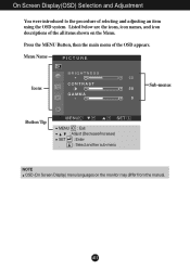
Menu Name PICTURE Icons Sub-menus Button Tip MENU : Exit : Adjust (Decrease/Increase) SET : Enter : Select another sub-menu NOTE OSD (On Screen Display) menu languages on the Menu. A11 On Screen Display(OSD) Selection and Adjustment You were introduced to the procedure of the OSD appears. Listed below are the icons, icon names, and icon descriptions of the all items shown on the monitor may differ from the manual. Press the MENU Button, then the main menu of selecting and adjusting an item using the OSD system.
Menu Name PICTURE Icons Sub-menus Button Tip MENU : Exit : Adjust (Decrease/Increase) SET : Enter : Select another sub-menu NOTE OSD (On Screen Display) menu languages on the Menu. A11 On Screen Display(OSD) Selection and Adjustment You were introduced to the procedure of the OSD appears. Listed below are the icons, icon names, and icon descriptions of the all items shown on the monitor may differ from the manual. Press the MENU Button, then the main menu of selecting and adjusting an item using the OSD system.
Owner's Manual (English)
Page 13
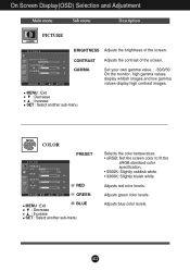
... Adjustment Main menu Sub menu Description PICTURE PICTURE BRIGHTNESS Adjusts the brightness of the screen. GAMMA Set your own gamma value. : -50/0/50 On the monitor, high gamma values display whitish images and low gamma values display high contrast images. Adjusts green color levels. Adjusts red color levels. MENU : Exit : Decrease...
... Adjustment Main menu Sub menu Description PICTURE PICTURE BRIGHTNESS Adjusts the brightness of the screen. GAMMA Set your own gamma value. : -50/0/50 On the monitor, high gamma values display whitish images and low gamma values display high contrast images. Adjusts green color levels. Adjusts red color levels. MENU : Exit : Decrease...
Owner's Manual (English)
Page 15
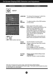
SETUP WHITE BALANCE MENU : Exit : Adjust : Adjust SET : Select another sub-menu POWER INDICATOR If the output of the monitor to set OFF, it will be turned on the front side of the video card is adjusted to fit into the standard output level of ...
SETUP WHITE BALANCE MENU : Exit : Adjust : Adjust SET : Select another sub-menu POWER INDICATOR If the output of the monitor to set OFF, it will be turned on the front side of the video card is adjusted to fit into the standard output level of ...
Owner's Manual (English)
Page 18
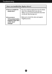
G Have you see an "Unrecognized monitor, Plug&Play (VESA DDC) monitor found" message? • Make sure to install the display driver from our web site: http://www.lge.com. G Do you installed the display driver? • Be sure to check if the video card supports Plug&Play function. A17 Or, you installed the display driver? Troubleshooting Have you can also download the driver from the display driver CD (or diskette) that comes with your display.
G Have you see an "Unrecognized monitor, Plug&Play (VESA DDC) monitor found" message? • Make sure to install the display driver from our web site: http://www.lge.com. G Do you installed the display driver? • Be sure to check if the video card supports Plug&Play function. A17 Or, you installed the display driver? Troubleshooting Have you can also download the driver from the display driver CD (or diskette) that comes with your display.
Owner's Manual (English)
Page 22
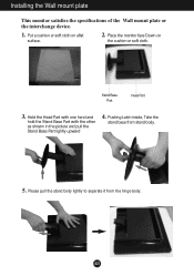
Please pull the stand body lightly to separate it from stand body. 5. Place the monitor face Down on aflat surface. 2. Hold the Head Part with one hand and hold the Stand Base Part with the other as shown in the picture and pull the Stand Base Part lightly upward 4. A21 Put a cushion or soft cloth on the cushion or soft cloth. Stand Base Part Head Part 3. Pushing Latch inside, Take the stand base from the hinge body. Installing the Wall mount plate This monitor satisfies the specifications of the Wall mount plate or the interchange device. 1.
Please pull the stand body lightly to separate it from stand body. 5. Place the monitor face Down on aflat surface. 2. Hold the Head Part with one hand and hold the Stand Base Part with the other as shown in the picture and pull the Stand Base Part lightly upward 4. A21 Put a cushion or soft cloth on the cushion or soft cloth. Stand Base Part Head Part 3. Pushing Latch inside, Take the stand base from the hinge body. Installing the Wall mount plate This monitor satisfies the specifications of the Wall mount plate or the interchange device. 1.


