Owners Manual
Page 3
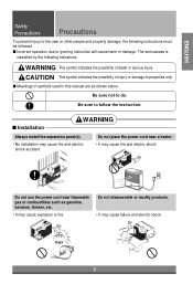
... sure to properties only. Gasolin 3 CAUTION This symbol indicates the possibility of injury or damage to follow the instruction. s Installation WARNING Always install the expansion panel(s). • No installation may cause explosion or fire. s Incorrect operation due to ignoring instruction will cause harm or damage.
... sure to properties only. Gasolin 3 CAUTION This symbol indicates the possibility of injury or damage to follow the instruction. s Installation WARNING Always install the expansion panel(s). • No installation may cause explosion or fire. s Incorrect operation due to ignoring instruction will cause harm or damage.
Owners Manual
Page 8
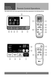
Operating Instructions Remote Control Operations The remote control and control panel will look like those represented in the following pictures. 6 COOL FAN DRY FAN INDOOR DESIRED ENERGY SAVER AIR PURIFIER CLEAN FILTER AIR PURIFIER Air Purifier Power 7 1 Temp 2 Fan Speed TIMER FAN SPEED MODE AIR PURIFIER TEMP POWER 4 Sleep Mode 8 3 54 3 7 2 1 Auto Timer Swing 5 Cool Energy Saver Fan Dry Timer F1 LOW F2 MED F3 HIGH TEMP 3 5 4 ˚F 6 2 5 1 Power 1 Temp 2 Fan Speed 4 Timer Mode 3 8
Operating Instructions Remote Control Operations The remote control and control panel will look like those represented in the following pictures. 6 COOL FAN DRY FAN INDOOR DESIRED ENERGY SAVER AIR PURIFIER CLEAN FILTER AIR PURIFIER Air Purifier Power 7 1 Temp 2 Fan Speed TIMER FAN SPEED MODE AIR PURIFIER TEMP POWER 4 Sleep Mode 8 3 54 3 7 2 1 Auto Timer Swing 5 Cool Energy Saver Fan Dry Timer F1 LOW F2 MED F3 HIGH TEMP 3 5 4 ˚F 6 2 5 1 Power 1 Temp 2 Fan Speed 4 Timer Mode 3 8

Owners Manual
Page 13
... 12. Using slit "B" • Fasten the stopper using 2 screw holes, and lead out the power cord through slit "B". AIR INTAKE (INLET GRILLE) 5. AIR DISCHARGE 6. CONTROL PANEL 10. POWER CORD 11. ENGLISH Hardware Installation Hardware Installation Product Features CAUTION: This appliance should be installed in accordance with national wiring regulations. REMOTE CONTROLLER...
... 12. Using slit "B" • Fasten the stopper using 2 screw holes, and lead out the power cord through slit "B". AIR INTAKE (INLET GRILLE) 5. AIR DISCHARGE 6. CONTROL PANEL 10. POWER CORD 11. ENGLISH Hardware Installation Hardware Installation Product Features CAUTION: This appliance should be installed in accordance with national wiring regulations. REMOTE CONTROLLER...


