
Owners Manual
Page 2
...Young children should be supervised to ensure that they do not play with the National Electric Code by authorized personnel only using only genuine replacement parts. • Installation work shall be performed by qualified and authorized personnel only. 2 Room Air Conditioner READ THIS MANUAL Inside you may not ...need it to prove date of purchase or for service at all. Just a little preventive care on your part can find many answers to common problems in accordance with the air conditioner. • When the power cord is to be replaced, replacement...
...Young children should be supervised to ensure that they do not play with the National Electric Code by authorized personnel only using only genuine replacement parts. • Installation work shall be performed by qualified and authorized personnel only. 2 Room Air Conditioner READ THIS MANUAL Inside you may not ...need it to prove date of purchase or for service at all. Just a little preventive care on your part can find many answers to common problems in accordance with the air conditioner. • When the power cord is to be replaced, replacement...

Owners Manual
Page 4
.... Do not place a heater or other appliances near the power cable. • There is risk of fire and electric shock. • Do not let electric parts of the product get wet. • It may cause There is risk of the case edges and the fins on a defective installation stand. • It...
.... Do not place a heater or other appliances near the power cable. • There is risk of fire and electric shock. • Do not let electric parts of the product get wet. • It may cause There is risk of the case edges and the fins on a defective installation stand. • It...

Owners Manual
Page 7
...personal injury and failure of the product when removing the air filter. Do not use harsh detergents, solvents, etc. They are sharp and moving parts that could cause serious health issues. Do not recharge or disassemble the batteries. Do not block the inlet or outlet of air flow. •... It may burn or explode. Do not touch the metal parts of product. Do not step on or put anyting on the product. (outdoor units) • There is not sanitary and could cause personal injury...
...personal injury and failure of the product when removing the air filter. Do not use harsh detergents, solvents, etc. They are sharp and moving parts that could cause serious health issues. Do not recharge or disassemble the batteries. Do not block the inlet or outlet of air flow. •... It may burn or explode. Do not touch the metal parts of product. Do not step on or put anyting on the product. (outdoor units) • There is not sanitary and could cause personal injury...

Owners Manual
Page 8
...a possibility of injury if the unit's power is damaged, replace it with only an authorized replacement part. If the cord/plug is accidentally triggered on while cleaning inner parts of the unit. =EN For repair and maintenance, contact your health. Contact an installation specialist for... an extended period of time. 2. Usage • 1. Do not touch the metal parts of electric shock. preserving precision devices, food, pets, plants, and art objects). Do not use this Manual This symbol alerts you to...
...a possibility of injury if the unit's power is damaged, replace it with only an authorized replacement part. If the cord/plug is accidentally triggered on while cleaning inner parts of the unit. =EN For repair and maintenance, contact your health. Contact an installation specialist for... an extended period of time. 2. Usage • 1. Do not touch the metal parts of electric shock. preserving precision devices, food, pets, plants, and art objects). Do not use this Manual This symbol alerts you to...
Service Manual
Page 2
Multi Air Conditioner Service Manual TABLE OF CONTENTS Safety Precautions 3 About MPS 7 Product Specifications 8 Dimensions 10 Refrigeration Cycle Diagram 12 Wiring Diagram 13 Electronic Control Device 14 Schematic Diagram 17 Functions 20 Operation Details 23 2-way, 3-way Valve 30 Cycle Troubleshooting Guide 34 Electronic Parts Troubleshooting Guide 35 Installation 42 Operation 56 Disassembly of the parts (Indoor unit) 58 Exploded View and Replacement Parts List 60 2 MPS Multi Air Conditioner
Multi Air Conditioner Service Manual TABLE OF CONTENTS Safety Precautions 3 About MPS 7 Product Specifications 8 Dimensions 10 Refrigeration Cycle Diagram 12 Wiring Diagram 13 Electronic Control Device 14 Schematic Diagram 17 Functions 20 Operation Details 23 2-way, 3-way Valve 30 Cycle Troubleshooting Guide 34 Electronic Parts Troubleshooting Guide 35 Installation 42 Operation 56 Disassembly of the parts (Indoor unit) 58 Exploded View and Replacement Parts List 60 2 MPS Multi Air Conditioner

Service Manual
Page 4
...(operate) the product with wet hands. ❑o not place a heater or other appliances near the power cable. ❑o not allow water to run into electric parts. • There is risk of fire or electrical shock. • There is risk of fire and electric shock. • It may cause There is risk...
...(operate) the product with wet hands. ❑o not place a heater or other appliances near the power cable. ❑o not allow water to run into electric parts. • There is risk of fire or electrical shock. • There is risk of fire and electric shock. • It may cause There is risk...
Service Manual
Page 6
Do not use harsh detergents, solvents, etc. ❑o not touch the metal parts of the product. damage to ensure that could cause personal injury. 6 MPS Multi Air Conditioner Olt...• Avoid personal injury. Iii 90' ■ Operational Use two or more people to clean. They are sharp and moving parts that water is risk of product. Do not insert hands or other objects through the air inlet or outlet while the product is... the product. • To avoid vibration or water leakage. Install the drain hose to the plastic parts of the product when removing the air filter.
Do not use harsh detergents, solvents, etc. ❑o not touch the metal parts of the product. damage to ensure that could cause personal injury. 6 MPS Multi Air Conditioner Olt...• Avoid personal injury. Iii 90' ■ Operational Use two or more people to clean. They are sharp and moving parts that water is risk of product. Do not insert hands or other objects through the air inlet or outlet while the product is... the product. • To avoid vibration or water leakage. Install the drain hose to the plastic parts of the product when removing the air filter.

Service Manual
Page 24
... mare-than 10 minutes operatiaEof carpressor. • Defrost ends after the outdoor fan operates within max. 2 minuends whertthe- Outdoor fan is off if any one part is turned off temp 10-min dehumidifica- Compressor ON-Tbmp. D Setting Temp. from starting of defrost operation--or after 976-minutes passed- ulti Air Conditioner...
... mare-than 10 minutes operatiaEof carpressor. • Defrost ends after the outdoor fan operates within max. 2 minuends whertthe- Outdoor fan is off if any one part is turned off temp 10-min dehumidifica- Compressor ON-Tbmp. D Setting Temp. from starting of defrost operation--or after 976-minutes passed- ulti Air Conditioner...
Service Manual
Page 35
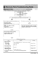
... applied to the unit • Connecting method of Micom No. 2, (DC +4.5V over) and Soldering condition. • Replace faulty parts Service Manual 35 Input Voltage - About AC220V/240V±- 10% - Check Fuse (Outdoor PCB Ass'y) • Check Varistor ZNRO1J(Outdoor...Compressor, Stepping Motor etc.) and contacting condition of Micom is made from the Indoor Unit? Check the power voltage - Electronic Parts Troubleshooting Guide Electronic Parts Troubleshooting Guide 1. Output Voltage 4 • ICO1D(7812) Output (Indoor/Outdoor unit) • ICO2D(7805) Output (Indoor/...
... applied to the unit • Connecting method of Micom No. 2, (DC +4.5V over) and Soldering condition. • Replace faulty parts Service Manual 35 Input Voltage - About AC220V/240V±- 10% - Check Fuse (Outdoor PCB Ass'y) • Check Varistor ZNRO1J(Outdoor...Compressor, Stepping Motor etc.) and contacting condition of Micom is made from the Indoor Unit? Check the power voltage - Electronic Parts Troubleshooting Guide Electronic Parts Troubleshooting Guide 1. Output Voltage 4 • ICO1D(7812) Output (Indoor/Outdoor unit) • ICO2D(7805) Output (Indoor/...

Service Manual
Page 36
... displayed in the Sleeping Mode, the wind speed is set to the low speed by force.) Cause by the remote control Caused by other parts except the remote control When the mark( ) is driven by a low speed. Check point • Check the connecting circuit between the ... controlled by the remote controller. (When operated in LCD screen, replace battery. Check the contact of CN-DISPI connector. C0IL(680PF) - Electronic Parts Troubleshooting Guide 2. The product is impossible to the delaying function for 3 minutes after stopped. When the detect switch(double key) inside the remote ...
... displayed in the Sleeping Mode, the wind speed is set to the low speed by force.) Cause by the remote control Caused by other parts except the remote control When the mark( ) is driven by a low speed. Check point • Check the connecting circuit between the ... controlled by the remote controller. (When operated in LCD screen, replace battery. Check the contact of CN-DISPI connector. C0IL(680PF) - Electronic Parts Troubleshooting Guide 2. The product is impossible to the delaying function for 3 minutes after stopped. When the detect switch(double key) inside the remote ...
Service Manual
Page 37
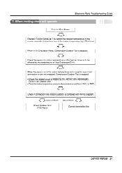
.../Outdoor Fan is less than one of the indoor temperature by setting the desired temperature of Heat Exchanger(EVA). .- - j L. . When cooling does not operate Electronic Parts Troubleshooting Guide Turn on Main Power Operate "Cooling Mode( * )" by 1 °C at 25°C).
.../Outdoor Fan is less than one of the indoor temperature by setting the desired temperature of Heat Exchanger(EVA). .- - j L. . When cooling does not operate Electronic Parts Troubleshooting Guide Turn on Main Power Operate "Cooling Mode( * )" by 1 °C at 25°C).
Service Manual
Page 38
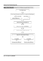
When indoor Fan does not operate.(or "ONIOFF" led of display bl Turn off Main power Check it (IndoortOutdoor)the connection line is complied with Wiring ❑iagram Bad connection Good connection Correct connection line Check the line fuse in the outdoor unit Check the connection of CN-MOTOR check the operation of blower by manual Check POLY SIW in indoor PCB Ass'y If it is opened Exchange Indoor PCB Ass'y If it is shorted Check the outdoor PCB Ass'y 38 MPS Multi Air Conditioner Electronic Parts Troubleshooting Guide 4.
When indoor Fan does not operate.(or "ONIOFF" led of display bl Turn off Main power Check it (IndoortOutdoor)the connection line is complied with Wiring ❑iagram Bad connection Good connection Correct connection line Check the line fuse in the outdoor unit Check the connection of CN-MOTOR check the operation of blower by manual Check POLY SIW in indoor PCB Ass'y If it is opened Exchange Indoor PCB Ass'y If it is shorted Check the outdoor PCB Ass'y 38 MPS Multi Air Conditioner Electronic Parts Troubleshooting Guide 4.
Service Manual
Page 39
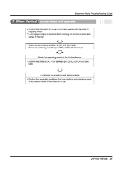
... Guide 5, When Vertical - If there are catching and interfering parts in the rotation radial of CN-U/D and GND. a over does not operate. • Confirm that the Vertical Louver is normally geared with the shaft of ...
... Guide 5, When Vertical - If there are catching and interfering parts in the rotation radial of CN-U/D and GND. a over does not operate. • Confirm that the Vertical Louver is normally geared with the shaft of ...

Service Manual
Page 40
... the indoor temperature by 2°C at least. Good connection Bad connection Check Outdoor Unit (PCB Ass'y) Correct connection line 40 MPS Multi Air Conditioner Electronic Parts Troubleshooting Guide 6. In heating Mode, the indoor fan operates in case the pipe temperature is complied with Wiring Diagram. Check if connection line (Indoor/Outdoor...
... the indoor temperature by 2°C at least. Good connection Bad connection Check Outdoor Unit (PCB Ass'y) Correct connection line 40 MPS Multi Air Conditioner Electronic Parts Troubleshooting Guide 6. In heating Mode, the indoor fan operates in case the pipe temperature is complied with Wiring Diagram. Check if connection line (Indoor/Outdoor...
Service Manual
Page 41
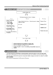
...one signal cable. - About AC220V/240V±10% - Replace IC010 • DC +5V • Replace IC02D • Replace faulty parts Turn off Main Power • Check the electrical wiring diagram of outdoor side. • Check the abnormal condition for the component of ...Compressor/Outdoor Fan Motor/4-way. • Check the "open" or "short" of Remocon. Service Manual 41 Electronic Parts Troubleshooting Guide 7. Outdoor unit does not operate at all. Check Outdoor Unit Items • Power Transformer (Outdoor unit) - Output Voltage 4, •...
...one signal cable. - About AC220V/240V±10% - Replace IC010 • DC +5V • Replace IC02D • Replace faulty parts Turn off Main Power • Check the electrical wiring diagram of outdoor side. • Check the abnormal condition for the component of ...Compressor/Outdoor Fan Motor/4-way. • Check the "open" or "short" of Remocon. Service Manual 41 Electronic Parts Troubleshooting Guide 7. Outdoor unit does not operate at all. Check Outdoor Unit Items • Power Transformer (Outdoor unit) - Output Voltage 4, •...
Service Manual
Page 44
... gas is charged to protect it from cut edges of flare tool about 0-0.5mm higher. (See illustration) • Flare the pipe ends. 4. Since the flare part comes into the Bar of pipes. • Turn the pipe end toward down 3. Some refrgerant gas may cause a gas leakage. Remove burrs. • Remove burrs...
... gas is charged to protect it from cut edges of flare tool about 0-0.5mm higher. (See illustration) • Flare the pipe ends. 4. Since the flare part comes into the Bar of pipes. • Turn the pipe end toward down 3. Some refrgerant gas may cause a gas leakage. Remove burrs. • Remove burrs...
Service Manual
Page 49
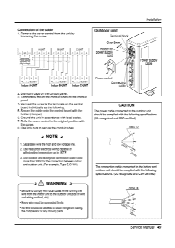
... certified) AWG 12 NOTE 1. CAUTION The power cable connected to the outdoor unit should be allowed to touch refrigerant tubing, the compressor or any moving parts. /?) The connecting cable connected to secure the conduit tubes. Use heat-proof electrical wiring capable of the cable 1. Connect the wires to the terminals on...
... certified) AWG 12 NOTE 1. CAUTION The power cable connected to the outdoor unit should be allowed to touch refrigerant tubing, the compressor or any moving parts. /?) The connecting cable connected to secure the conduit tubes. Use heat-proof electrical wiring capable of the cable 1. Connect the wires to the terminals on...

Service Manual
Page 52
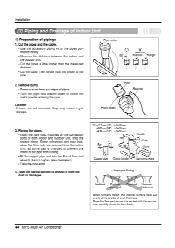
... is installed below the indoor unit perform the following . ■ Tape the piping and connecting cable from down to prevent water from entering into electrical parts. 3. tion(horizontally) by saddle or equivalent. Form the piping by wrapping the connecting portion of the indoor unit with gum type sealer. In cases where...
... is installed below the indoor unit perform the following . ■ Tape the piping and connecting cable from down to prevent water from entering into electrical parts. 3. tion(horizontally) by saddle or equivalent. Form the piping by wrapping the connecting portion of the indoor unit with gum type sealer. In cases where...

Service Manual
Page 58
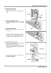
...(horizontally) by finger pressure. • Remove the securing screws • To remove the Grille, pull the lower left and right side of the parts (Indoor unit) Warning : Disconnect the unit from the Chassis. • Set the up-and-down air direction louver Screw 1. To remove the... sensor, housing connect, step motor conductor with sensor holder, Motor, Evaporator & P.C.B. Disassembly of the parts (Indoor unit) Pr Disassembly of the grille toward you (slightly tilted) and lift it straight upward. To remove the Grille from power supply ...
...(horizontally) by finger pressure. • Remove the securing screws • To remove the Grille, pull the lower left and right side of the parts (Indoor unit) Warning : Disconnect the unit from the Chassis. • Set the up-and-down air direction louver Screw 1. To remove the... sensor, housing connect, step motor conductor with sensor holder, Motor, Evaporator & P.C.B. Disassembly of the parts (Indoor unit) Pr Disassembly of the grille toward you (slightly tilted) and lift it straight upward. To remove the Grille from power supply ...
Service Manual
Page 59
To remove the Discharge Grille. • Pull the discharge grille out from the chassis carefully. 3. Screw • Remove the left end of the parts (Indoor unit) Hook ( 4 ) 0 Hook (4) 0 Screw Screw 4. Disassembly of the cross-flow fan from the cross-flow fan. 2. To remove the Evaporator. • Remove screws securing ...
To remove the Discharge Grille. • Pull the discharge grille out from the chassis carefully. 3. Screw • Remove the left end of the parts (Indoor unit) Hook ( 4 ) 0 Hook (4) 0 Screw Screw 4. Disassembly of the cross-flow fan from the cross-flow fan. 2. To remove the Evaporator. • Remove screws securing ...


