Service Manual
Page 2
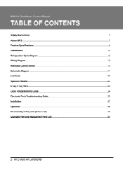
Multi Air Conditioner Service Manual TABLE OF CONTENTS Safety Precautions 3 About MPS 7 Product Specifications 8 Dimensions 10 Refrigeration Cycle Diagram 12 Wiring Diagram 13 Electronic Control Device 14 Schematic Diagram 17 Functions 20 Operation Details 23 2-way, 3-way Valve 30 Cycle Troubleshooting Guide 34 Electronic Parts Troubleshooting Guide 35 Installation 42 Operation 56 Disassembly of the parts (Indoor unit) 58 Exploded View and Replacement Parts List 60 2 MPS Multi Air Conditioner
Multi Air Conditioner Service Manual TABLE OF CONTENTS Safety Precautions 3 About MPS 7 Product Specifications 8 Dimensions 10 Refrigeration Cycle Diagram 12 Wiring Diagram 13 Electronic Control Device 14 Schematic Diagram 17 Functions 20 Operation Details 23 2-way, 3-way Valve 30 Cycle Troubleshooting Guide 34 Electronic Parts Troubleshooting Guide 35 Installation 42 Operation 56 Disassembly of the parts (Indoor unit) 58 Exploded View and Replacement Parts List 60 2 MPS Multi Air Conditioner

Service Manual
Page 3
...to do. a Install the panel and the cover of control box securely. • There is risk of fire or electric shock. 1 Service Manual 3 ACAUTION This symbol indicates the possibility of injury or damage. ■ Meanings of symbol used in this appliance on a dedicated circuit. ...8226; There is risk of fire or electric shock. AWARNING) ■ Installation Do not use a defective or underrated circuit breaker. Use this manual are as shown below. Always ground the prodm ucti. Always install a dedicated circult and breaker. • Improper wiring or installation may condense ...
...to do. a Install the panel and the cover of control box securely. • There is risk of fire or electric shock. 1 Service Manual 3 ACAUTION This symbol indicates the possibility of injury or damage. ■ Meanings of symbol used in this appliance on a dedicated circuit. ...8226; There is risk of fire or electric shock. AWARNING) ■ Installation Do not use a defective or underrated circuit breaker. Use this manual are as shown below. Always ground the prodm ucti. Always install a dedicated circult and breaker. • Improper wiring or installation may condense ...

Service Manual
Page 5
... product. ure. Do not store or use flammable gas or combustibles near the product. • There is risk of fire, electric shock, or product damage. Service Manual 5 Safety Precautions If strange sounds, or smell or smoke comes from product.
... product. ure. Do not store or use flammable gas or combustibles near the product. • There is risk of fire, electric shock, or product damage. Service Manual 5 Safety Precautions If strange sounds, or smell or smoke comes from product.
Service Manual
Page 7
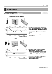
Service Manual 7 Indoor Temp (°C) About MPS MPS (Multi Power System) Conventional (On/Off Operation) About MPS Indoor Temp (CC) ON OFF ON OFF 27 4 + Ir 4 -II. &#...
Service Manual 7 Indoor Temp (°C) About MPS MPS (Multi Power System) Conventional (On/Off Operation) About MPS Indoor Temp (CC) ON OFF ON OFF 27 4 + Ir 4 -II. &#...

Service Manual
Page 9
Heating Cooling Heating Dimensions(W x H x D) dB(A) W A Btu/Irw mm Net. Weight kg Service Valve mm(Inch) Ref rigerant(R-22) g Airflow Direction Control(Up & Down) Remote Controller Type Sleeping Operation Drain Hose... - - - 3.6 2.4 1.2 at 230V 10, 208/230V, 60Hz Indoor - - 8 Outdoor 63 Indoor Outdoor 40/38/36 at 7.5m 0 L.G.D Wireless 0 0 Service Manual 9 Product Specifications 2. HMH036KDT1 Item Operation Unit Cooling Capacity Heating Capacity Moisture Removal Power Source Btu/h(kcal/h) i /h 0, V, Hz Air Circulation m:/min Noise Level (Hi/Med/...
Heating Cooling Heating Dimensions(W x H x D) dB(A) W A Btu/Irw mm Net. Weight kg Service Valve mm(Inch) Ref rigerant(R-22) g Airflow Direction Control(Up & Down) Remote Controller Type Sleeping Operation Drain Hose... - - - 3.6 2.4 1.2 at 230V 10, 208/230V, 60Hz Indoor - - 8 Outdoor 63 Indoor Outdoor 40/38/36 at 7.5m 0 L.G.D Wireless 0 0 Service Manual 9 Product Specifications 2. HMH036KDT1 Item Operation Unit Cooling Capacity Heating Capacity Moisture Removal Power Source Btu/h(kcal/h) i /h 0, V, Hz Air Circulation m:/min Noise Level (Hi/Med/...
Service Manual
Page 11
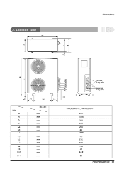
2. Outdoor Unit Dimensions I DIM W H D L1 L2 L3 L4 L5 L6 L7 L8 L9 L10 L11 L7 L6 L8 MODEL mm ill al mm mm mm fri ITI mm mm M M mm mm mm mm mm Gas side 3-way valve Liquid side 2-way valve L9 HMC036KDT1, HMH036KDT1 870 1038 320 360 340 25 1035 25 546 160 160 44 64.5 50 Service Manual 11
2. Outdoor Unit Dimensions I DIM W H D L1 L2 L3 L4 L5 L6 L7 L8 L9 L10 L11 L7 L6 L8 MODEL mm ill al mm mm mm fri ITI mm mm M M mm mm mm mm mm Gas side 3-way valve Liquid side 2-way valve L9 HMC036KDT1, HMH036KDT1 870 1038 320 360 340 25 1035 25 546 160 160 44 64.5 50 Service Manual 11

Service Manual
Page 13
... ANIV AWAY VALVE SE -SOLENOID VALVE or ENTT-H1 cenKP`r°wEm °r:71"sEioR2 K 4.1 MAC CC PCB ASSY C THERMISPORCRIRE) THERMISIONAIR) 11 THERIAISTORPSCRAFIGE-O THEFRAISTORPSCSARGEM 3854A24002B Service Manual 13 CAPACITOR TM TB -TERMINAL BLOCK - la-- • •0, 10F- 3IRISE WA/1115A) CN-COM 1 MAW AC PCB ASSY CN-FAR Cli.COM 2 . -- Cr A-Cr...
... ANIV AWAY VALVE SE -SOLENOID VALVE or ENTT-H1 cenKP`r°wEm °r:71"sEioR2 K 4.1 MAC CC PCB ASSY C THERMISPORCRIRE) THERMISIONAIR) 11 THERIAISTORPSCRAFIGE-O THEFRAISTORPSCSARGEM 3854A24002B Service Manual 13 CAPACITOR TM TB -TERMINAL BLOCK - la-- • •0, 10F- 3IRISE WA/1115A) CN-COM 1 MAW AC PCB ASSY CN-FAR Cli.COM 2 . -- Cr A-Cr...

Service Manual
Page 19
Eof I gig he E2 a ttt Service Manual 19 vE 1t • El s U0 = El I ng. Schematic Diagram A cRT? EX 0 g L.
Eof I gig he E2 a ttt Service Manual 19 vE 1t • El s U0 = El I ng. Schematic Diagram A cRT? EX 0 g L.
Service Manual
Page 21
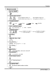
... or heating. Up to 30°C(86'F) JET COOL Heatingf Down to 16°C(.60°F) Up to 18°C(64°F) - Reset • RESET Service Manual 21 Remote Controller Operation ON/OFF Functions Operation Mode Selection *AO *AO Cooling Operation Mode.( * ) Auto Operation Mode.( A ) (Cooling (Heating model only) model only) Healthy...
... or heating. Up to 30°C(86'F) JET COOL Heatingf Down to 16°C(.60°F) Up to 18°C(64°F) - Reset • RESET Service Manual 21 Remote Controller Operation ON/OFF Functions Operation Mode Selection *AO *AO Cooling Operation Mode.( * ) Auto Operation Mode.( A ) (Cooling (Heating model only) model only) Healthy...
Service Manual
Page 23
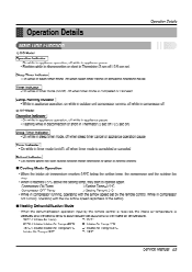
I Operation Details Operation Details 1) C/O Model Operation Indicator • On while in appliance operation, off while in appliance pause • Flashing while in disconnection or short in Thermistor (3 sec off / 0.5 sec on) Sleep Timer Indicator • On while in sleep timer mode, off when sleep timer cancel or appliance operation pause Timer Indicator • On while in timer mode (on /off), off when timer mode is automatically set by the remote control is received, the intake air temperature is detected and the setting temp is completed or canceled. Running Incidator •...
I Operation Details Operation Details 1) C/O Model Operation Indicator • On while in appliance operation, off while in appliance pause • Flashing while in disconnection or short in Thermistor (3 sec off / 0.5 sec on) Sleep Timer Indicator • On while in sleep timer mode, off when sleep timer cancel or appliance operation pause Timer Indicator • On while in timer mode (on /off), off when timer mode is automatically set by the remote control is received, the intake air temperature is detected and the setting temp is completed or canceled. Running Incidator •...
Service Manual
Page 25
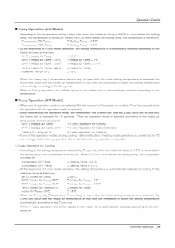
Operation Details uzzy OpCrdtion (C/O Mvdc • According to the-temperature-set-by-Fuzzy-ruler when-the-intake-air-temp-is-075--S-er-mere-below the setting temp, the compressor is turned on. Compressor ON Temp ~SettingTemp405°C Compressor OFF Temp Setting Temp + 0 5°C • At the beginning of Fuzzy intake air temp-at that time. ≤ Intake-Air Temp ≤ IntakeAir Temp < O intake Air Temp ≤ hitctke Air Temp < O Intake Air Temp + 0. 18°C-≤-intak en p < Intake Intake Air Temp When 0.5°C or more above the setting temp, the compressor ...
Operation Details uzzy OpCrdtion (C/O Mvdc • According to the-temperature-set-by-Fuzzy-ruler when-the-intake-air-temp-is-075--S-er-mere-below the setting temp, the compressor is turned on. Compressor ON Temp ~SettingTemp405°C Compressor OFF Temp Setting Temp + 0 5°C • At the beginning of Fuzzy intake air temp-at that time. ≤ Intake-Air Temp ≤ IntakeAir Temp < O intake Air Temp ≤ hitctke Air Temp < O Intake Air Temp + 0. 18°C-≤-intak en p < Intake Intake Air Temp When 0.5°C or more above the setting temp, the compressor ...

Service Manual
Page 29
...-seeereling-te-the-eenditien-of the-appliance is on the main unit, the appliance operates according to indicate that the remote controtsrarral cannot be received Service Manual 29
...-seeereling-te-the-eenditien-of the-appliance is on the main unit, the appliance operates according to indicate that the remote controtsrarral cannot be received Service Manual 29

Service Manual
Page 31
...gauge indicates lkg/cm'g. 7. Disconnect the charge set to 15 minutes. 3. Operate the unit for 3 minutes, then connect the manifold gauge to the service port. 4. Open the Low-handle valve on the gauge slightly to operate the valve stems. 2. IL IL 2-way, 3-way Valve • ...1.8kg.m.(4.2kg*m/5.5kg*m) - Immediately set the gas side valve to the closed position. - Set the liquid side valve to the closed position. 6. Service Manual 31 (1) Pumping dow Indoor unit H Liquid side Close 2-Way valve Outdoor unit Gas side 3-Way c valve I I11 Indoor unit . Be sure ...
...gauge indicates lkg/cm'g. 7. Disconnect the charge set to 15 minutes. 3. Operate the unit for 3 minutes, then connect the manifold gauge to the service port. 4. Open the Low-handle valve on the gauge slightly to operate the valve stems. 2. IL IL 2-way, 3-way Valve • ...1.8kg.m.(4.2kg*m/5.5kg*m) - Immediately set the gas side valve to the closed position. - Set the liquid side valve to the closed position. 6. Service Manual 31 (1) Pumping dow Indoor unit H Liquid side Close 2-Way valve Outdoor unit Gas side 3-Way c valve I I11 Indoor unit . Be sure ...
Service Manual
Page 33
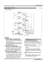
...the valve at a time (approximately 150g each time) while operating the air conditioner in the cooling cycle; Mount the valve stem nuts and the service port nut. - This is not sufficient, wait approximately 1 minute and then repeat the procedure(pumping down-pin). 4. (3) Gas Charging (After ...5. Because you are using a gas cylinder. 3. Be sure to the charging cylinder. - Service Manual 33 Connect the gauge to check for gas leakage. Purge the air from the gas side valve's service port. Connect the charge hose which you are charging with larger amounts of refrigerant, it can...
...the valve at a time (approximately 150g each time) while operating the air conditioner in the cooling cycle; Mount the valve stem nuts and the service port nut. - This is not sufficient, wait approximately 1 minute and then repeat the procedure(pumping down-pin). 4. (3) Gas Charging (After ...5. Because you are using a gas cylinder. 3. Be sure to the charging cylinder. - Service Manual 33 Connect the gauge to check for gas leakage. Purge the air from the gas side valve's service port. Connect the charge hose which you are charging with larger amounts of refrigerant, it can...
Service Manual
Page 35
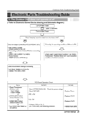
... load(Indoor/Outdoor Fan Motor, Compressor, Stepping Motor etc.) and contacting condition of Micom No. 2, (DC +4.5V over) and Soldering condition. • Replace faulty parts Service Manual 35 Output Voltage 4 • ICO1D(7812) Output (Indoor/Outdoor unit) • ICO2D(7805) Output (Indoor/Outdoor unit) 4 • ICO1A(KIA7036, Reset IC) X01(8MHz) PCB...
... load(Indoor/Outdoor Fan Motor, Compressor, Stepping Motor etc.) and contacting condition of Micom No. 2, (DC +4.5V over) and Soldering condition. • Replace faulty parts Service Manual 35 Output Voltage 4 • ICO1D(7812) Output (Indoor/Outdoor unit) • ICO2D(7805) Output (Indoor/Outdoor unit) 4 • ICO1A(KIA7036, Reset IC) X01(8MHz) PCB...
Service Manual
Page 37
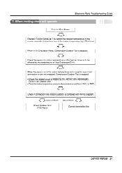
... indoor temperature and connector are in Air Circulation Mode, Compressor/Outdoor Fan is complied with Wiring Diagram. Check Outdoor Unit (PCB Ass'y) Correct connection line Service Manual 37 3. j L. . Good connection Bad connection ..., ,.. When the sensor circuit for indoor temperature is disconnected or not(About 10kn/ at least. 4,› When in bad connection...
... indoor temperature and connector are in Air Circulation Mode, Compressor/Outdoor Fan is complied with Wiring Diagram. Check Outdoor Unit (PCB Ass'y) Correct connection line Service Manual 37 3. j L. . Good connection Bad connection ..., ,.. When the sensor circuit for indoor temperature is disconnected or not(About 10kn/ at least. 4,› When in bad connection...
Service Manual
Page 39
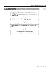
... rotating the Vertical Louver with the shaft of Stepping Motor. • If the regular torque is DC +12V between pin D(RED) of the Vertical Louver Service Manual 39
... rotating the Vertical Louver with the shaft of Stepping Motor. • If the regular torque is DC +12V between pin D(RED) of the Vertical Louver Service Manual 39
Service Manual
Page 41
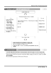
... transmitted or received between indoor and outdoor. 8. Electronic Parts Troubleshooting Guide 7. Input Voltage - Check the power voltage • Replace Trans - About AC220V/240V±10% - Service Manual 41 Output Voltage 4, • ICO1D(7812) Output (Indoor/Outdoor unit) 40 • IC02D(7805) Output (Indoor/Outdoor unit) 4, • IC01A(KIA7036, Reset IC) X01(8MHz...
... transmitted or received between indoor and outdoor. 8. Electronic Parts Troubleshooting Guide 7. Input Voltage - Check the power voltage • Replace Trans - About AC220V/240V±10% - Service Manual 41 Output Voltage 4, • ICO1D(7812) Output (Indoor/Outdoor unit) 40 • IC02D(7805) Output (Indoor/Outdoor unit) 4, • IC01A(KIA7036, Reset IC) X01(8MHz...

Service Manual
Page 43
... lower left and the hole should be slightly slant to the outdoor side. Mount the installation plate on the wall with 70mm dia. Installation ,A3a. Service Manual 43 The meeting point of the extended line is the center of the hole. • Drill the piping hole at either the right or the...
... lower left and the hole should be slightly slant to the outdoor side. Mount the installation plate on the wall with 70mm dia. Installation ,A3a. Service Manual 43 The meeting point of the extended line is the center of the hole. • Drill the piping hole at either the right or the...

Service Manual
Page 45
... its hole. • Turn it clockwise approx. 90 °and remove it. (2) Pull (:) Press I Connecting cable Gas side piping Liquid side piping ❑rain hose Service Manual 45 Be sure that drain hose locates at the upper side can be a reason that drain water overflows drain pan inside the unit. 2) Connection of...
... its hole. • Turn it clockwise approx. 90 °and remove it. (2) Pull (:) Press I Connecting cable Gas side piping Liquid side piping ❑rain hose Service Manual 45 Be sure that drain hose locates at the upper side can be a reason that drain water overflows drain pan inside the unit. 2) Connection of...


